Pfannenberg PWS Series Setup guide

ELECTRO-TECHNOLOGY FOR INDUSTRY
PWS Series
Air/Water Heat Exchangers
Safety for man, machine and the environment®
Installation, Operation and Service Manual

TABLE OF CONTENTS
SECTION 1: HOW TO USE THIS MANUAL ..........1
SECTION 2: RECEIVING INSPECTION ................2
2.1 Unpacking...........................................................2
2.2 Included Items ...................................................2
2.3 Review of ID Plate...............................................2
SECTION 3: HANDLING......................................3
3.1 Transporting .......................................................3
3.2 Storage ................................................................3
SECTION 4: INSTALLATION................................3
4.1 Pre-installation testing ......................................3
4.2 Installation onto the electrical panel................3
4.3 Power connection...............................................4
4.4 Cooling Water Connection.................................4
4.5 Condensation Water Connection ......................4
4.6 Door Contact.......................................................5
SECTION 5: OPERATING CONDITIONS..............6
5.1 Requirements .....................................................6
5.2 Theory of Operation...........................................6
SECTION 6: UNIT START-UP...............................7
6.1 General ................................................................7
6.2 Setting the Operating Parameters....................7
6.2.1 Units with Water (Solenoid) Valve
and Thermostat ...............................................7
6.2.2 Units without Water Valve and Thermostat ..7
SECTION 7: MAINTENANCE...............................8
SECTION 8: TROUBLESHOOTING ......................8
SECTION 9: DESIGN DATA..................................8
9.1 Water Quality Notes ...........................................8
9.2 SCCR Determination.........................................10
SECTION 10: WARRANTY INFORMATION ...... 12

PWS Series Air/Water Heat Exchangers
1
SECTION 1: HOW TO USE THIS MANUAL
This manual contains information on the installation
and operation of PWS Series bolt-on cooling units
intended to be door and side mounted on electrical
panels.
These devices are designed to dissipate heat from
sealed electrical panel enclosures and housings.
The temperature of the cooling liquid supplied to
the air/water heat exchanger must be at least 10° C
colder than the heat exchanger inlet air temperature
in order to ensure that the unit function correctly.
Conventions used:
Hint: A hint contains additional information on the
action or instruction being described
WARNING!
If the information following this is not strictly
followed there is a danger to health or life.
WARNING!
If the information following this is not strictly
followed there is a danger to health or life
due to electrical shock.
The technical data specific to each cooling unit,
including installation connections and operational
data, are contained on a separate data sheet
supplied with each unit.
2
SECTION 2: RECEIVING INSPECTION
2.1 Unpacking
Prior to and during unpacking the cooling unit,
visually inspect it to determine if any damage has
occurred during shipping. Make sure that it does not
contain any loose components. Before discarding
any packaging materials: Look for loose parts, dented
or scratched panels or fluids.
If any damage is noted it shall be reported
immediately to the delivering carrier and a claim
should be filed with them. Pfannenberg cannot
accept responsibility for freight damage that may
occur; we will assist you in any way possible if the
need arises to file a claim.
In case of a warranty claim, the following information
is required: exact details of the fault (including
photographs, if possible), the cooling unit part
number and serial number are required.
WARNING!
Burrs caused by production may be present
on the metal edges of the cooling unit. Always
wear protective gloves when carrying out
installation or maintenance work.
2.2 Included Items
The following items should be included:
Cooling unit
Mounting cutout
Manual
Technical Data Sheet
PWS Series accessory pack typically includes:
• Sealing strips
• Threaded mounting studs
• Mounting bolts, nuts and washers
• Condensate hose (PWS 7k series only)
• Door contact connector/jumper
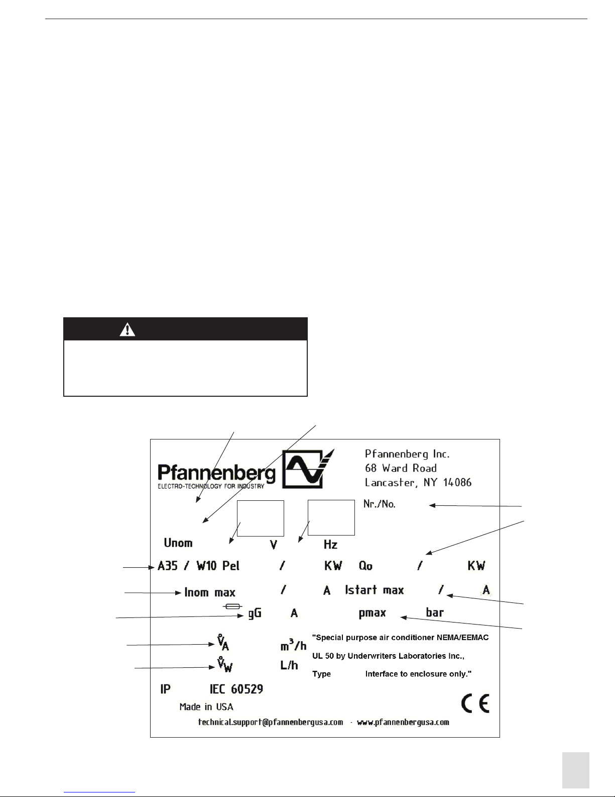
2.3 Review of ID Plate
The ID plate is located on the left side of the
cooling unit. The technical data specific to
the cooling unit is located on the ID plate as
shown below.
Power
Consumption
Part Number
Serial #
Starting
Current
Max Allowable
Water Pressure
Rated Cooling
Capacity
(50 Hz Value) (60 Hz Value)
Model Number
(50 Hz Value) (60 Hz Value)
(50 Hz Value) (60 Hz Value)
(50 Hz Value) (60 Hz Value)
Nominal
Operating
Voltage
Nominal
Operating
Frequency
Rated Current
Pre-Fuse T
Air Flow Rate
Water Flow Rate
PWS Series Air/Water Heat Exchangers
3
SECTION 3: HANDLING
3.1 Transporting
The cooling unit shall only be moved in the fully
assembled condition.
If the cooling unit is being shipped with an electrical
panel enclosure it shall be packed separately from
the electrical enclosure.
3.2 Storage
The cooling unit shall not be exposed to
temperatures exceeding +70ºC.
If the device is stored or transported at temperatures
below freezing, the water circuit must be completely
emptied using compressed air.
WARNING!
Failure to observe these requirements
will void the warranty.
SECTION 4: INSTALLATION
4.1 Pre-installation testing
Before mounting the cooling unit to the electrical
panel enclosure it should be tested to verify function.
Note: All devices are checked for leaks before leaving
the factory.
We recommend installing a door contact switch
to turn the device off when the electrical panel
enclosure door is opened.
4.2 Installation onto the electrical panel
Before connecting the cooling unit to the power
supply, verify that the following are correct:
Voltage must be within ± 10% of the value listed on
the ID plate.
Voltage frequency must be within ± 3 Hz of the value
listed on the ID plate
Ambient temperature must be below +55ºC (for
options see “setting the operating parameters”
section)
Place the drilling template supplied with the cooling
unit onto the applicable mounting surface of the
electrical panel enclosure.
WARNING!
Metal chips from drilling and cutting the openings
may damage the electrical panel enclosure. Take
precautions required to prevent chips and debris
from getting into the enclosure.
WARNING!
Watch out for sharp edges created when drilling
and/or cutting the enclosure.
Drill holes in the electrical panel enclosure to
match the unit and cut out air flow openings.
Install the two supplied stud bolts (in the accessory
pack) into the top two mounting hole locations of
the cooling unit.

4
WARNING!
Please note the information on the “Thread
Reach for Set Screw” label attached to the
cooling unit. If the noted installed thread depth
is exceeded the cooling unit may be damaged.
Install the cooling unit mounting insulation strips (in
the accessory pack) to the cooling unit as noted on
the individual cooling unit information sheet.
Make sure that the insulation strips are correctly
attached and placed correctly on the cooling unit.
The correct fitting and location of the insulation
strips is required for the proper operation of the
cooling unit.
Attach the cooling unit to the electrical panel
enclosure by use of the stud bolts inserted as
described above.
WARNING!
Do not move the cooling unit by the piping.
Doing so will damage the cooling unit and
void the warranty.
The cooling unit is then completely attached to the
electrical panel enclosure from inside the enclosure
by use of the screws and washers supplied in the
accessory pack.
Tighten the fasteners until the cooling unit insulation
strips are compressed to a thickness of 2 mm
(approximately .080”)
Install Drain hose barb (provided in accessory bag
for PWS 3k series only) then attach the condensate
drainage hose to the drain.
Reinstall the cover using the original mounting
screws.
4.3 Power connection
WARNING!
Make sure that the main power supply to the
cooling unit is turned off while making the
power connections.
The cooling unit power supply shall be fused as
indicated on the unit ID plate by means of a series
connected power line connection.
All power connections and / or repairs, if or when
required, shall only be carried out by authorized,
trained electricians.
Power supply connection
PWS 7K series provide a molded cord suitable for the
rated voltage of the unit.
PWS 3k series have hard wire terminal
(PWS 7K series only)
Both the main power supply voltage and frequency
shall correspond to the nominal values shown on the
cooling unit ID plate.
Connect the main power supply to the cooling unit
as indicated by the label located on the cooling unit
and on the individual cooling unit data sheet.
WARNING!
During installation, service technician must
verify and mark voltage as connected on
service cover warning sticker.
4.4 Cooling Water Connection
PWS 7K series uses Teflon©tape and brass fittings.
Use flexible pressure-resistant (>10bar) hose for the
cooling water connection and secure properly with
clamps.
PWS 3K series has multiple options for connections,
a barb is provided for use with flexible pressure-
resistant hose and clamp.
Observe flow direction (labels on the device located
next to the water connections) Check for leaks.
Protect the water circuit against contamination and
excessive pressure (please refer to the “Water Quality
Notes“ section. The maximum permissible operating
pressure is 10 Bar.

PWS Series Air/Water Heat Exchangers
5
SECTION 4: INSTALLATION CON'T
4.5 Condensation Water Connection
Drainage hose must be secured in place with clamps.
To ensure reliable drainage of condensation water,
please note the following:
The drain hose shall not be kinked. Hose cross-section
must not be constricted in any way. The drainage hose
must slope in the right direction.
To avoid excessive condensation water amounts,
please note the following:
Adjust the cooling water temperature to the cooling
performance required.
Only use the device on sealed electrical panels and
housings.
Set the desired temperature only as low as is really
necessary (to avoid the cooled air from dropping
below the dewpoint).
4.6 Door Contact
To avoid an increased production of condensate
and for safety reasons a door limit switch should be
connected to the terminals provided.
WARNING!
No external voltage may be applied to the door contact
circuit or damage to the cooling unit may result.
In order to prevent any interference from outside
signals, it is recommended that a shielded cable with
a twisted pair leads be used for the connection. The
cable shielding can be connected on one side to the PE
(ground) connection point provided on the cooling unit.
If the use of a shielded cable is not possible, the cable
that is used must not be routed in the immediate
vicinity of potential sources of interference such as
power supply lines , components with a relatively high
electromagnetic emission (EMI), etc.
If no door contact switch is used, the connecting
terminals must be jumpered for the cooling unit to
operate.

6
SECTION 5: OPERATING CONDITIONS
5.1 Requirements
Before connecting the cooling unit to the power
supply, verify that the following are correct.
Voltage must be within ± 10% of the value listed on
the ID plate.
Voltage frequency must be within ± 3 Hz of the value
listed on the ID plate
Ambient temperature must be below +55ºC (for
options see Section 6.5)
Make sure that the airflow inside of the electrical
panel enclosure is not restricted by internal
components.
WARNING!
If the cooling unit is being mounted on the door of
the electrical panel enclosure, it must be confirmed
that the door hinges can support the additional
weight of the cooling unit and that the electrical
panel enclosure is securely fastened so that the
panel enclosure will not topple over.
5.2 Theory of Operation
The cooling units are available in two options:
A.) With Water (solenoid) Valve and Thermostat
B.) Without Water Valve and Thermostat
A.) With Water (solenoid) Valve and Thermostat
∞
1 Water Valve (solenoid)
2 Heat Exchanger (condensor)
3 Fan
4 Thermostat with Temperature Sensor
The water valve (1) controls if water is allowed to
flow through the cooling unit.
As the water flows through the heat exchanger (2)
it absorbs the heat from air in the electrical panel
enclosure while also dehumidifying it. This process
lowers the temperature of the air in the electrical
panel enclosure.
This is accomplished by the fan (3) pulling in the hot
air from the electrical panel enclosure and pushing
it through the heat exchanger (2) and back into the
electrical panel enclosure at a lower temperature.
The cooling unit (with water valve and thermostat)
is electronically controlled. To accomplish this a
temperature sensor monitors the temperature inside
the electrical panel enclosure and regulates the
function of the water valve.
B.) Without Water Valve and Thermostat
∞
1 Water Inlet
2 Heat Exchanger (condensor)
3 Fan
The flow of water through the unit is regulated by a
control system provided by the user outside of the
coolling unit.
As the water flows through the heat exchanger (2)
it absorbs the heat from air in the electrical panel
enclosure while also dehumidifying it. This process
lowers the temperature of the air in the electrical
panel enclosure.
This is accomplished by the fan (3) pulling in the hot
air from the electrical panel enclosure and pushing
it through the heat exchanger (2) and back into the
electrical panel enclosure at a lower temperature.
PWS Series Air/Water Heat Exchangers
7
SECTION 6: UNIT START-UP
6.1 General
The cooling unit is equipped with an temperature
control system. The temperature of the air pulled in
from the electrical panel enclosure into the cooling
unit is measured by a temperature sensor.
WARNING!
Ambient conditions and temperatures
in the electrical panel must be in accordance
with the values indicated in the cooling unit
information sheet.
WARNING!
Unit must be operated with the cover installed.
Unit can not cool properly when cover
is not in place.
6.2 Setting the Operating Parameters
6.2.1 Units with Water (Solenoid) Valve
and Thermostat
The cooling unit fan runs continuously.
The solenoid valve controls cooling water flow
according to the internal temperature setting in the
switch cabinet.
The desired internal temperature of the switch
cabinet is set using the thermostat. Factory setting is
at 35°C / 95°F. Adjustment range min. 8°C / 46.4°F -
max. 50°C / 122°F.
Electrical panel enclosure internal temperature > the
desired value set using the thermostat
Solenoid valve open Coolant flows.
Electrical panel enclosure internal temperature < the
desired value set using the thermostat .
Solenoid valve shut coolant does not flow.
If door contact is opened then the unit cycles off.
Temperature Monitoring
If the internal temperature of the electrical panel
enclosure deviates more than 10º C from the desired
value set (factory setting 35°C / 95°F) using the
thermostat then the zero potential two-way switch is
triggered.
This switch is wired to the terminal strip.
Wiring diagram
(Technical sheet)
(Wiring diagram on device)
6.2.2 Units without Water Valve and Thermostat
The cooling unit fan runs continuously.
The cooling water flow is controlled centralized
water flow control supplied by the customer.
The door contact cycles the unit on / off. The door
contact output notifies of an open door condition.
SECTION 7: MAINTENANCE
Pfannenberg air/water heat exchangers are
maintenance-free.
Use of a water filter is essential if the cooling water
is contaminated. Please refer to the “Water Quality
Notes“ section.
Check the condensation water drainage equipment
at regular intervals.
SECTION 8: TROUBLESHOOTING
Condensation water drainage out of the electrical
panel enclosure must be ensured when the device is
installed.
To prevent frost damage the temperature in the
water circuit must not fall below the minimum
permissible water temperature of +1°C anywhere in
the system.
If the device is stored or transported at temperatures
below freezing the water circuit must be completely
emptied using compressed air.

8
SECTION 9: DESIGN DATA
Please refer to the cooling unit individual
technical data sheets for the following:
Dimensional Data
Mounting Cutout
Circuit Diagrams
9.1 Water Quality Notes
The following guidelines must be complied with to ensure safe and reliable operation of air/water heat
exchangers.
Cooling water should not contain any sedimentation, should be of low hardness (low carbon hardness in
particular), especially for re-cooling. However, it should not be so soft that it corrodes material/s used in the
exchanger.
When recycling cooling water the saline content due to evaporation of larger quantities of water must not be too
high (increasing concentrations of dissolved substances increase electrical conductivity, resulting in the water
becoming more corrosive).
Constantly remove some enriched water and replace it with an equal amount of fresh water.
Water containing gypsum is unsuitable for cooling, as it tends to cause scale deposits, which are very hard to
remove.
Cooling water should be iron- and manganese-free (deposits leading to piping blockage may otherwise result).
Organic substances (sludge and microbiological contaminants)should only be present in the water in very small
amounts.
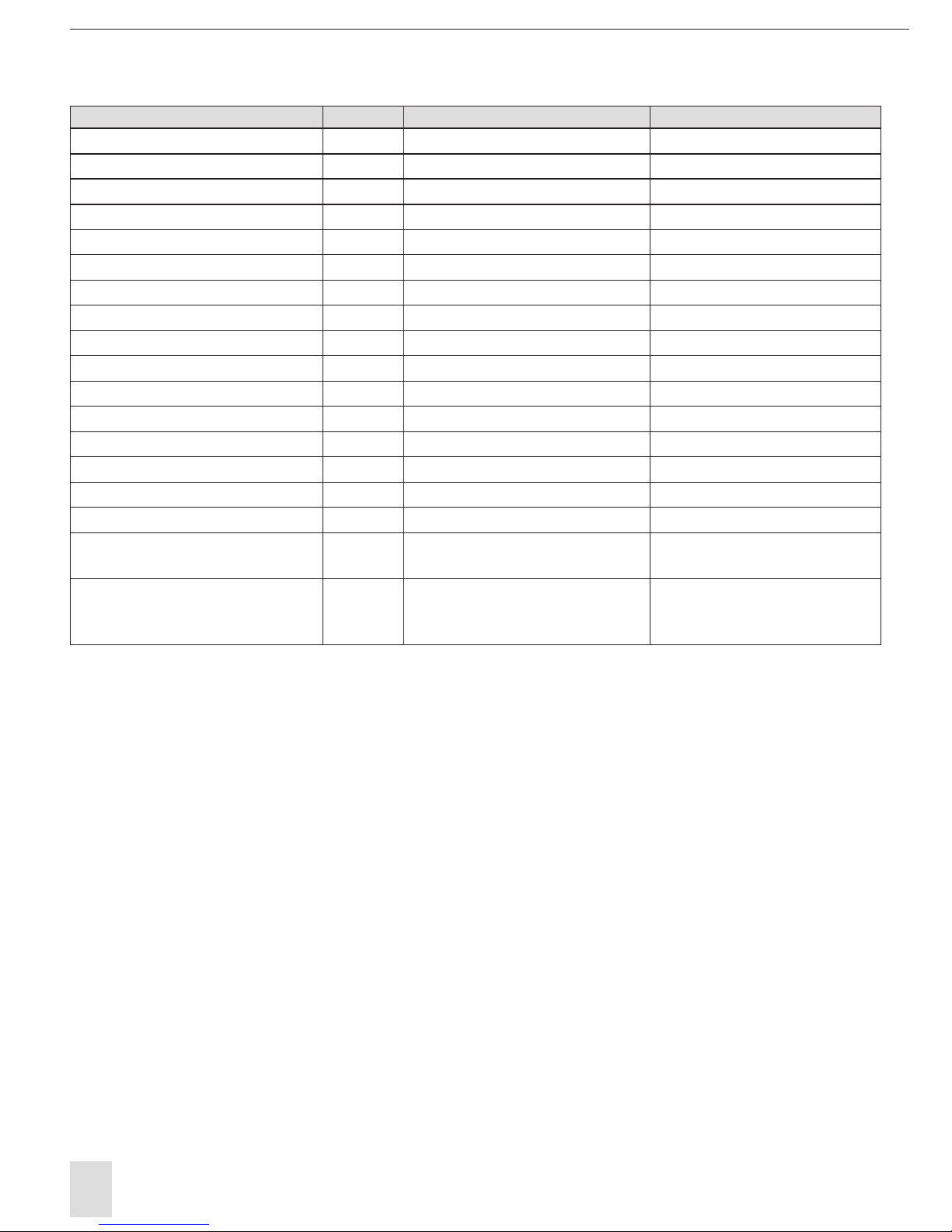
Common contamination forms and remedies
Water Contamination Remedy
Mechanical contamination
Filter water using -Sieve filters
- Gravel filters
- Cartridge filters -Pre-coated filters
Excessive hardness Soften water using ion exchange
Moderate mechanical contaminant and hardness
promoting substance content Treat water using stabilisers or dispersants
Moderate chemical contaminant content Treat water using passivation media and / or inhibitors
Biological contamination - sludge bacteria, algae Treat water with biocides
PWS Series Air/Water Heat Exchangers
9
The characteristics of any additives or system water ought not to deviate greatly from the hydrological
data given below.
Hydrological Data Model: Standard Device Model: VA
pH value 7 - 8.5 6 - 9
Carboxylic Acid °dH > 3 < 8 1 - 12
Free carbonic acid mg/dm3 8 - 15 1 - 100
Associated carbonic acid mg/dm3 8 - 15 not present
Corrosive carbonic acid mg/dm3 0 0 - 400
Sulphides not present not present
Oxygen mg/dm3 < 10 < 10
Chloride ions mg/dm3 < 50 < 200
Sulphate ions mg/dm3 < 250 < 500
Nitrates and nitrites mg/dm3 < 10 < 100
CSB mg/dm3 < 7 < 40
Ammonia mg/dm3 < 5 < 20
Iron mg/dm3 < 0.2 not present
Manganese mg/dm3 < 0.2 not present
Conductivity mS/cm < 2200 < 4000
Evaporation residue mg/dm3 < 500 < 2000
Potassium permanganate
consumption mg/dm3 < 25 < 40
Suspended matter mg/dm3 < 3 > 3
< 15 split-stream cleansing
recommended > 15 constant
cleaning recommended

10
9.2 SCCR Determination
Article 409 of the 2005 National Electric Code (NFPA
70) requires Industrial Control Panels (electrical
panel enclosures) to be marked with a short
circuit current rating. As specified in the National
Electric Code, the Standard for Industrial Control
Equipment, UL508A-2001, Supplement SB, provides
an accepted method for determining the short
circuit current rating of the control panel. The link
to spreadsheets provide guidance for industrial
control panel manufacturers who purchase the
discreet components and assemble combination
motor controllers within their panels to achieve a
combination short circuit rating that is higher than
the lowest rated individual component.
Using the technical data sheet and the information
on the cooling unit ID plate, identify the full load
current conditions for the appropriate voltage. The
installation of the cooling unit should be calculated
as a dedicated branch circuit for determining the
SCCR value. All selections should be evaluated based
on the current UL standards for UL508a.
Table 1
Room cooling units rated-Load Current, Amperage
Single Phase33 Phase350 KA 100 KA 200 KA
110 - 120 V 200 - 208 V 220 - 240 V 254 - 277 V 440 - 480 V
Peak
Let-thru
Current2
Max
Fuse1Ipx 103Max
Fuse1Ipx 103Max
Fuse1Ipx 103
9.9 16.0 5.4 8.8 5.0 8.0 6.65 Less 1.8 Less 1000 15 50 KA n/a n/a
16.1 34.0 8.9 18.6 8.1 17.0 --- --- --- --- 2000 30 50 KA 15 100 KA n/a
--- --- --- --- --- --- --- --- Over 1.8 5000 15 50 KA 30 100 KA 30 200 KA
1Maximum CC class Fuse size that can achieve this branch circuit SCCR value. Smalller values may be used and still achieve equal rating.
2Circuit capacity amperes based on UL 484 table 52.1
3Individual units running amperes can be obtained on each unit's technical data sheet.
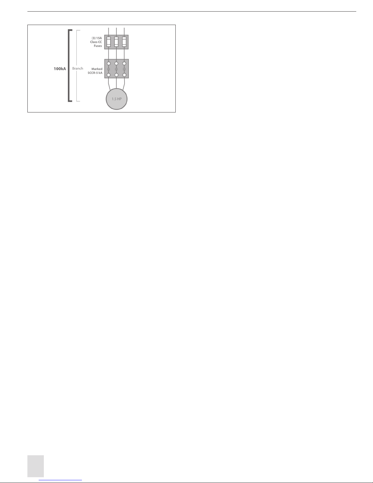
Example 2: DTS 35xx 460V units has a 5KA IR value
based on UL 484 table 52.1 (see Table 1) and the
amp draw of the unit. If a 15amp Class CC current
limiting feeder circuit is used in combination with
the DTS35xx 460V unit, the maximum allowable
Ipeak of the 15 amp Class CC fuse at an available RMS
fault current of 200 kA is 1700 amps (figure 2). This
value does not exceed the allowable Ipeak of this
unit based on UL SCCR value of Table 52.1. Therefore,
the individual branch circuit SCCR value of this series
combination can support 200 kA IR. (See figure 1.)
Figure 2
PWS Series Air/Water Heat Exchangers
11
Option 1: UL 508a reference SB4.2
According to UL508A Supplement SB, if a panel
contains no current-limiting devices, its SCCR
depends on the “weakest” or lowest rated
component or combination within the panel.
However, Supplement SB also states that if current-
limiting fuses are used in the feeder circuit, and if the
highest instantaneous current reached during the
first half cycle of a fault is less than or equal to the
lowest rated SCCR in any branch circuit, the SCCR
of the current limiting fuse can be applied to the
combination.
When the specified branch circuit protection related
to the high fault short circuit current rating is a Class
CC,G,J,L,RK1, RK5 or T fuse, a fuse of a different class
is able to be used at the same high fault rating where
the peak let through current and I2t of the new fuse
is not greater than that of the specified fuse.
Option 2: UL 508a reference SB4.3
An alternate method of achieving a high short circuit
rating is by applying a power transformer with an
isolated secondary winding, the short circuit current
rating on the line side of the transformer shall be one
of the following:
For a power transformer rated not more than 10
kVA, and where the short circuit current rating of
all components in the secondary circuit are not
less than 5kA, the short circuit current rating of the
primary overcurrent protective device is able to be
assigned to the line side of the power transformer
circuit.
For a power transformer rated not more that 5kVA
and a 120V maximum secondary voltage, and where
the short circuit current rating of all components in
the secondary circuit are not less than 2kA, the short
circuit rating of the primary overcurrent protective
device is able to be assigned to the line side of the
power transformer circuit.
Option 3: UL 508a reference SB4.2
The combinations listed in the linked spreadsheets
(www.ul.com/controlequipment/shortcircuit.html)
may be applied in a manufacturer’s Listed industrial
control panel without further evaluation or specific
documentation in the manufacturer’s UL Procedure
pages.
The spreadsheets cover the application of individual
components, including a disconnecting means, an
over current protective device, motor controller
and motor overload protection, as a combination
motor controller having specified ratings, including
a short-circuit current rating (SCCR). Each of the
individual components is Listed or Recognized to the
requirements in the applicable component Standard.
The specified ratings for the combination motor
controller may be applied to the end-product
equipment only when all of the specific components
listed are provided in the end-product equipment
and installed according to any applicable conditions
of acceptability.
Components other than those identified in the
combination motor controller and connected in the
power circuit of the combination motor controller
will require additional evaluation.
Figure 1

12
SECTION 10: WARRANTY INFORMATION
(WARRANTY IS VALID FOR 1 YEAR)
Warranty becomes null and void:
In case of improper usage of the unit, noncompliance with operating conditions or nonobservance of instructions
the warranty becomes null and void.
If operated in rooms in which corrosives or acids are present in the atmosphere.
In case of damage caused by contaminated or jammed air filters.
If a non-authorized person interrupts the cooling circulation, modifies the unit or changes the serial number.
In case of damage caused by transport or by accidents.
For the exchange of parts by non-authorized companies.
In order to maintain your warranty rights please observe the following when returning the unit.
Enclose an exact description of the fault in the shipping package.
Enclose proof of delivery (delivery note or copy of invoice).
Return the unit together with all accessories; use the original packaging or packaging of equivalent quality, send
the unit freight prepaid and covered by an adequate transport insurance.

Pfannenberg Incorporated
68 Ward Road, Lancaster, New York 14086
Phone: 716-685-6866
Fax: 716-681-1521
email: [email protected]
www.pfannenbergusa.com
ELECTRO-TECHNOLOGY FOR INDUSTRY
Rev. A
Org 08/09
© 2013 Pfannenberg Incorporated

ELECTRO - F
Ü
R DIE INDUSTRIE
PWS
Installation, Betrieb und Service Manual

INHALTSVERZEICHNIS
ABSCHNITT 1: WIE IST DIES HANDBUCH .......1
ABSCHNITT 2: EMPFANG INSPECTION2 .........
2.1
Auspacken
......................................................2
2.2
Enthaltene Einzelteile
.....................................2
2.3
Überprüfung von ID
.........................................2
ABSCHNITT 3: HANDLING3 ............................
3.1
Transporting
...................................................3
3.2
Lagerung
.........................................................3
SEKTION 4: INSTALLATION..............................3
4.1
Pre-Installation Testen
....................................3
4.2
Die Montage auf der Schalttafel
......................3
4.3
Leistung Verbindung
........................................4
4.4
Kühlwasseranschluss
.......................................4
4.5
Kondensation Wasseranschluss
.......................4
4.6
Türkontakt
......................................................5
ABSCHNITT 5: BETRIEB CONDITIONS6 ...........
5.1
Bedarf
.............................................................6
5.2
Theorie der Arbeitsweise
.................................6
ABSCHNITT 6: UNIT ANFANG .........................7
6.1
General
...........................................................7
6.2
Einstellen der Betriebsparameter
....................7
6.2.1
Einheiten mit Wasser (Solenoid) Ventil
und Thermostat7 ..........................................
6.2.2
Geräte ohne Wasserventil und Thermostat ..7
ABSCHNITT 7: MAINTENANCE8 .........................
ABSCHNITT 8: TROUBLESHOOTING8 .............
ABSCHNITT 9: DESIGN DATEN............................8
9.1
Wasser Qualitätshinweise
................................8
9.2
SCCR Bestimmung
.........................................10
ABSCHNITT 10: GARANTIE INFORMATION..12
PWS
ABSCHNITT 1: WIE DIESE ANLEITUNG ZUR NUTZUNG
Dieses Handbuch enthält Informationen über die
Installation und den Betrieb von PWS Series bolzen
an Kühleinheiten vorgesehen Tür und Seiten an
elektrischen Platten montiert werden.
Diese Geräte sind so ausgelegt, Wärme von
abgedichteten elektrischen Panel Gehäuse und
Gehäuse abzuführen. Die Temperatur der
Kühlflüssigkeit auf den Luft / Wasser
kälter als der Wärmetauscher Zulufttemperatur,
damit die Einheitsfunktion korrekt zu gewährleisten.
Verwendete Konventionen:
Hinweis: Ein Hinweis enthält weitere Informationen
über die Handlung oder Anweisung beschrieben
wird,
WARNUNG!
Wenn die Informationen folgende ist dies
nicht strikt befolgt gibt es eine Gefahr für
die Gesundheit oder das Leben.
WARNUNG!
Wenn die Informationen folgende ist dies
nicht strikt befolgt gibt es eine Gefahr für
die Gesundheit oder das Leben durch
elektrischen Schlag.
Die technischen Daten des jeweiligen Kühleinheit,
einschließlich der Installationsanschlüsse und
Betriebsdaten werden auf einem separaten
Datenblatt enthalten ist, mit jeder Einheit
zugeführt wird.

ABSCHNITT 2: Eingangsprüfung
2.1
Auspacken
Vor und während der Kühleinheit Auspacken visuell
inspizieren, um zu bestimmen, ob ein Schaden
während des Transports aufgetreten ist. Stellen Sie
sicher, dass es keine losen Komponenten enthält. Vor
jedem Verpackungsmaterial entsorgen: Suchen Sie
nach losen Teile, verbeult oder zerkratzt Platten oder
Flüssigkeiten.
Sollte ein Schaden festgestellt wird unverzüglich
den Spediteur mitgeteilt werden und eine
Forderung soll mit ihnen eingereicht werden.
Pfannenberg kann keine Verantwortung für
Transportschäden übernehmen, die auftreten
können; Wir werden Sie auf jede erdenkliche Weise
unterstützen, wenn die Notwendigkeit, einen
Anspruch Datei entsteht.
Im Falle eines Garantieanspruchs, werden die
folgenden Informationen erforderlich: genaue
Angabe der Störung (einschließlich Fotos, wenn
möglich), sind die Kühleinheit Teilenummer und
Seriennummer erforderlich.
2.2
Enthaltene Einzelteile
Die folgenden Punkte sollten enthalten
sein: Kühlaggregat
Einbauausschnitt
Handbuch
Technisches Datenblatt
PWS
•
Dichtleisten
•
Gewindebefestigungsbolzen
•
Befestigungsschrauben, Muttern und
Unterlegscheiben
•
Kondensatschlauch (PWS 7k-Serie)
•
Türkontakt
2.3
Überprüfung von ID
Die ID Die technischen Daten spezifisch für
die Kühleinheit auf der ID
WARNUNG!
Graten durch die Produktion verursacht
werden, können an den Metallkanten der
Kühleinheit vorhanden sein. Tragen Sie
immer Schutzhandschuhe bei der Installation
oder der Durchführung von
Wartungsarbeiten.
Teilenummer Modell-Nr
Energieverbr
auch
Nennstrom
Pre-Sicherung
TLuftdurchsat
Wasseflussrte
Betriebs
spannun
g
Serial #
Anlaufstrom
Max zulässiger
Wasserdruck
Frequenz

PWS
ABSCHNITT 3: HANDLING
3.1
Transporting
Die Kühleinheit ist nur im vollständig bewegt
werden
zusammengebauten Zustand.
Wenn die Kühleinheit mit einer elektrischen Platte
Gehäuse verschifft sie sind getrennt von dem
elektrischen Gehäuse verpackt werden.
3.2
Lagerung
Die Kühleinheit ist nicht ausgesetzt
werden
Temperaturen über +70 º C.
Wenn das Gerät gespeichert ist, oder bei
Temperaturen unter dem Gefrierpunkt transportiert,
muss der Wasserkreislauf vollständig unter
Verwendung von Druckluft entleert wird.
WARNUNG!
Fehler diese Anforderungen werden
zum Erlöschen der Garantie
zu beobachten.
ABSCHNITT 4: INSTALLATION
4.1
Pre-Installation Testen
Vor der Montage der Kühleinheit an der Schalttafel
Gehäuse sollte es Funktion zu überprüfen, werden
getestet.
Hinweis: Alle Geräte sind auf undichte Stellen
überprüft, bevor sie das Werk verlassen.
Es wird empfohlen, ein Türkontaktschalter der
Installation der Vorrichtung zu deaktivieren,
wenn die Schalttafel Gehäusetür geöffnet wird.
4.2
Die Montage auf der Schalttafel
Vor dem
Anschluss überprüft die Kühleinheit an die
Stromversorgung, dass die folgenden richtig
sind:
Spannung muss innerhalb seines ± auf der ID -
Platte enthalten ist 10% des Werts.
Spannungsfrequenz muss innerhalb seines ± auf
der ID - Platte 3 aufgeführten Hz des Wertes
Umgebungstemperatur unter +55 sein muss º C
(Optionen siehe „ Einstellen der Betriebsparameter “
Abschnitt)
Platzieren Sie die Bohrschablone mit der
Kühleinheit auf die anwendbaren
Befestigungsfläche der zugeführten
Schalttafel
WARNUNG!
Metallspäne vom Bohren und Schneiden der
Öffnungen können die Schalttafel Gehäuse
beschädigen. Treffen Sie Vorkehrungen
erforderlich Späne und Schmutz zu verhindern,
dass in das Gehäuse zu bekommen.
WARNUNG!
Achten Sie auf scharfe Kanten entstehen, wenn
das Bohren und / oder das Gehäuse zu
schneiden.
Die Bohrungen in der Schalttafel Gehäuse des
Geräts anzupassen und Luftstromöffnungen
ausgeschnitten.
Installieren der beiden mitgelieferten
Stiftschrauben (im Beipack) in den beiden oberen
Befestigungsloch Stellen der Kühleinheit.
Other manuals for PWS Series
1
Table of contents
Languages:
Other Pfannenberg Industrial Equipment manuals

Pfannenberg
Pfannenberg PWI 6152 Series User manual

Pfannenberg
Pfannenberg PWS 6502 Series User manual

Pfannenberg
Pfannenberg PKS 30 2 Series Product guide

Pfannenberg
Pfannenberg PWS 6302 460V User manual

Pfannenberg
Pfannenberg PWI Series User manual

Pfannenberg
Pfannenberg PWS 6502 T 230V User manual

Pfannenberg
Pfannenberg PA 10/ 20 User manual

Pfannenberg
Pfannenberg PWS 7032-24V Series User manual

Pfannenberg
Pfannenberg PWI 6502 T Series User manual

Pfannenberg
Pfannenberg PWS 7502 User manual


