Promation Engineering P9-120N4-HR User manual

Installation & Operation
Manual
This IOM is for the following
ProMation Engineering Products:
P9-120N4-HR
P9-230N4-HR
P10-120N4-HR
P10-230N4-HR

This page intentionally left blank
Contents
2 . . . . . . . . . . . . . . . . . . . Product Specifications
3 . . . . . . . . . . . . . . . . . . . Shipping and Handling
3 . . . . . . . . . . . . . . . . . . . Product Mounting and Setup
3 . . . . . . . . . . . . . . . . . . . Installation Notes
4 . . . . . . . . . . . . . . . . . . . Wiring Diagram
4 . . . . . . . . . . . . . . . . . . . Torque Switches
5 . . . . . . . . . . . . . . . . . . . Layout of Controller
6 . . . . . . . . . . . . . . . . . . . Check End of Travel Settings
6 . . . . . . . . . . . . . . . . . . . Status Indicators
7 . . . . . . . . . . . . . . . . . . . Adjusting the actuator CW position
8 . . . . . . . . . . . . . . . . . . . Adjusting the actuator CCW position
9 . . . . . . . . . . . . . . . . . . . Adjusting the actuator Auxiliary Switches
10 . . . . . . . . . . . . . . . . . . Mechanical Data
11 . . . . . . . . . . . . . . . . . . Mechanical Data
12-14 . . . . . . . . . . . . . . . Commissioning
15 . . . . . . . . . . . . . . . . . . AutoCalibration Procedure
IOM Template Master.indd
Page 1 of 17 P2/3 Series HV-TS AdVanced Proportional Control
FM_P213 HV-PN4-HR (-TS)_Ver M 070721
Table of Contents
2 ................... Product Specifications
3 ................... Shipping and Handling
3 ................... Product Mounting and Setup
3 ................... Installation Notes
4 ................... Wiring Diagram
5 ................... Diagram of Controller
6 ................... Setting Limit Switches and Auxiliary Switches (Cams)
7 ................... Cam Adjustments
8 ................... Pre Calibration Preparation
8 ................... Calibration
9-11 ................ Calibrating the proportional control board
12 .................. Complete Calibration
13 .................. Confirm Controller End of Travel
14 .................. Mechanical Data
15 .................. Mechanical Data
16 .................. Commissioning
16 .................. Commissioning for TS units
16 .................. Testing Torque Switch Electrical Operation
17 .................. Commissioning for TS units (continued)
Page 1 of 17 P9/10 HV-N4 Series
Field Manual
P9/10 HV-PN4-HR (-TS)
High Resolution
Proportional Control
Powered Feedback
8P35ISO5211 F16 R75
FM_P213 HV-PN4-HR (-TS)_Ver M 070721
Introduction
This document provides necessary information for set-up, calibration, testing and use of the P Series quarter-turn
electric actuators stated on the cover page. Each unit is shipped from the factory with initial calibration of mechanical
stops, cams and switches completed for 0-90 degree operation. However, these are general settings and serve as
a starting point for proper calibration of the actuator in its real-world application.
Safety
Safety is a basic factor any time you maintain and operate mechanical equipment. Appropriate handling
methods and proper use of tools and personal protective equiptment (PPE) can help prevent serious accidents
which can cause injuries to you or a fellow worker. This manual was created to enable a trained user to install,
adjust and troubleshoot your ProMation actuator.
Only competent and trained personnel should install, maintain and operate ProMation actuators. Any work
related to this actuator must be carried out in accordance with this manual and related codes and regulations.
Local workplace health and safety rules must always be followed.
Duty cycle
Duty cycle is the percent of time that an actuator spends running as a fraction of the total time. Duty Cycle is
directly related to heat; excessively repositioning an actuator typically results in motor overheating which can
cause permanent damage and/or reduced service life.
Duty cycle can be calculated as follows:
(example P2 series actuator running 3 seconds ON and 30 seconds OFF)
Runtime = 3s, Total time = 3s + 30s = 33s, therefore this duty cycle would be 9% (3/33)
Additionally, ProMation P series actuators are designed for a maximum of 1200 starts per hour (one start every
3 seconds maximum).
Duty Cycle Chart
Page 2 of 17 P9/10 HV On/O Series
P9/10 SD
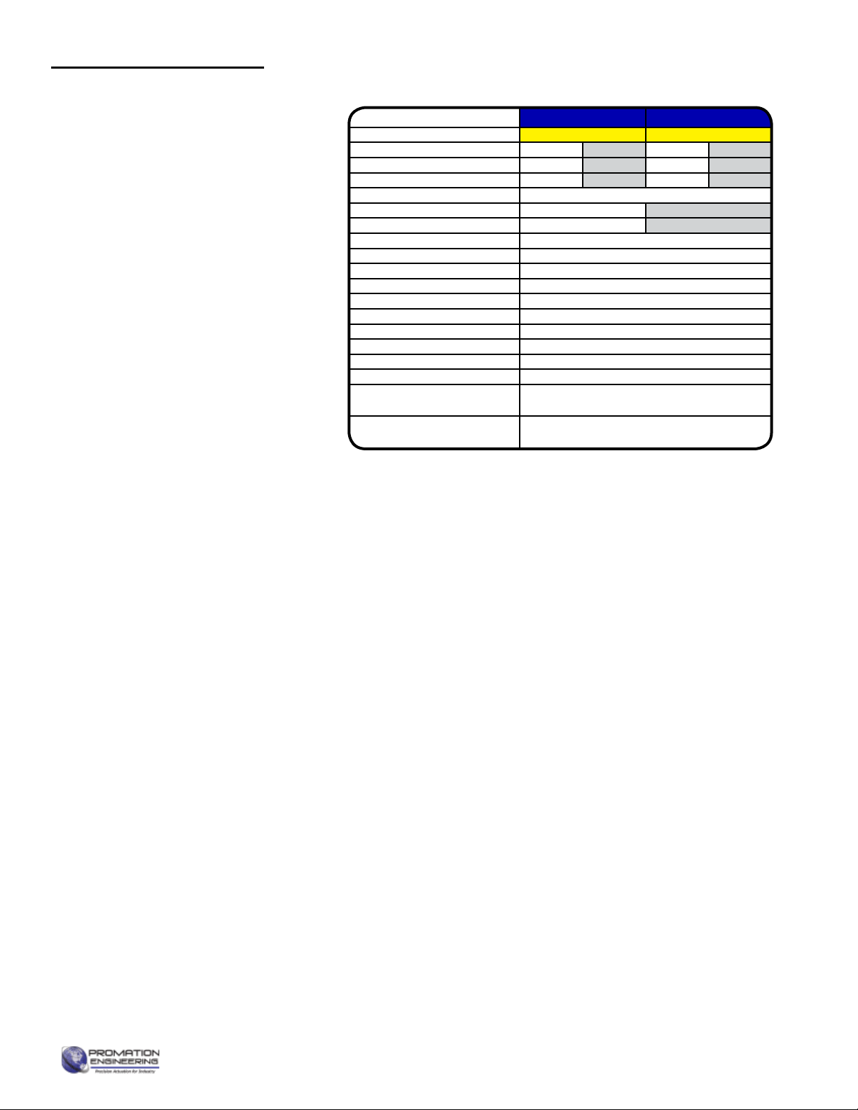
Actuator Speci cations P9 P10
Torque “lb/Nm 17500”lbs/2000Nm 22000”lbs/2500Nm
Supply Voltage 120vac 230vac 120vac 230vac
Max Inrush Current 5.8A 3.8A 6.5A 4.0A
Running Current 3.3A 2.1A 4.0A 2.3A
Motor Split Phase Capacitor
Runtime (90°@60Hz) 58 sec 58 sec
Runtime (90O@50Hz) 70 sec 70 sec
Duty Cycle 25%, Proportional: Managed (75% maximum)
Motor Starts 1200 per hour
Weight 145lbs/66kg
Mechanical Connections ISO5211 F16 Rnd 75mm
Electrical Entry (2) 3/4” NPT
Electrical Terminations 12-16ga
Environmental Rating NEMA 4/4X
Manual Override 15.6” Handwheel
Control On/O -Jog, Proportional
Actuator Case material Aluminum Alloy, Powder coated
Motor Protection 230°F/110°C Thermal F* Class
*Totally Enclosed Non-Ventilated Motors
Ambient Temperature
Operating Range
-22°F to +125°F
-30°C to +52°C
Product Specications
FM_P213 HV-PN4-HR (-TS)_Ver M 070721
1. This actuator is shipped in the FULLY CW position (2 color position indicator
shows “CLOSE” and the Reference Dimple aligns with “0”).
2. NOTE, THIS ACTUATOR MUST HAVE WATER TIGHT EMT FITTINGS, WITH
CONDUIT DRAINAGE INSTALLED AND POWER SUPPLIED TO UNIT TO
KEEP THE HEATER WARM AT THE TIME OF INSTALLATION.
3. Storage: This unit should NOT be stored outside unless it is powered up
and has proper conduit terminations. When NOT powered up, it should be
stored in a clean, dry environment at all times.
4. This actuator has been factory calibrated to operate between 0 degrees and
90 degrees. Most quarter-turn products will not require recalibration of
these settings. If any travel adjustment is necessary, please refer to page 10.
Cam adjustments instructions, pages 6-7 are included for reference only -- the
proportional controller should be used for any changes to positioning.
5. The actuator CANNOT operate with a rotation greater than
95 degrees.
1. Fully CLOSE the valve or damper to which the actuator is to be mounted.
• Keep in mind this actuator rotates CW (as viewed from above the unit) when driving CLOSED.
2. Assemble necessary linkage components and attach the actuator to the driven device.
3. Tighten mounting bolts, making sure actuator is centered on the device drive shaft.
4. Utilize the handwheel to check for unobstructed manual operation from fully CCW to fully CW positions BEFORE
applying power to the unit.
5. Make the electrical connections per wiring diagram on page 4.
• Connect POWER to terminals marked 1 and 2 on the switch card (430-10100).
• Connect CONTROL to (DHC-100 J2) terminals marked 4 and 5 OR 4 and 6 per Wiring Diagram on page 4.
• Terminals 7-12 on the switch card (430-10100) can be used for the (adjustable) aux switches. They are dry type
Form C rated 10A @ 250vac MAX.
6. Do NOT apply power at this time.
• These actuators are designed to be used between a horizontal and upright
position. Do NOT mount the assembly with the actuator top below a horizontal
position.
• When installing conduit, use proper techniques for entry into the actuator. Use
drip loops to prevent conduit condensate from entering the actuator.
• Mechanical travel stops are factory calibrated for 90 degree operation. These
stops are NOT designed to adjust mechanical rotation by more than +/- 3
degrees, they are for positioning the handwheel only.
• Both NPT conduit ports MUST use proper equipment to protect the NEMA 4X
integrity of the housing.
• The internal heater is to be used in ALL applications.
• Do NOT install the actuator outdoors or in humid environments unless it is
powered up and the heater is functioning.
• Use proper wire size to prevent actuator failure (see chart on page 4 for proper
wire sizing).
• All terminals accept 12-16AWG solid/stranded wire.
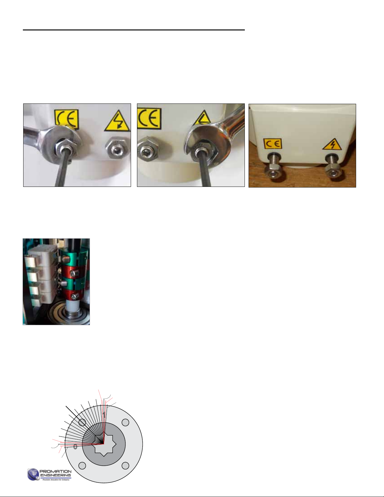
Identifying Torque Switch Units:
• -TS in Product Name on label.
• Units with Torque Switches have
additional switches mounted on
the motor plate (see photo).
Page 3 of 17 P9/10 HV-N4 Series
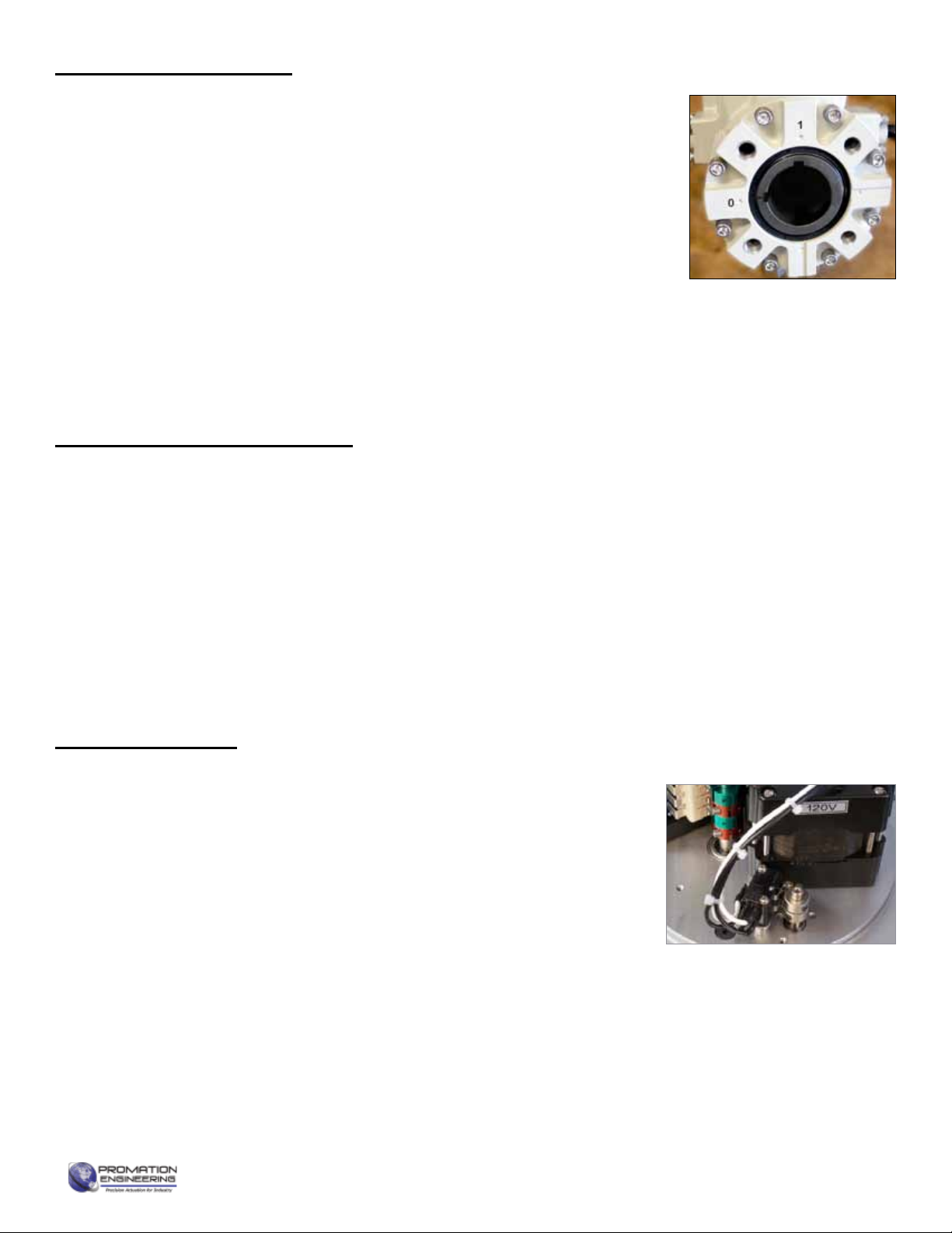
The actuator is shown in its
fully CW position. This view
of actuator shows the two
drive keyways machined
into the female drive socket.
Shipping and Handling
Product Mounting and Setup
Installation Notes

FM_P213 HV-PN4-HR (-TS)_Ver M 070721
Proportional Control
Torque Switches (if equipped)
For units equipped with torque switches:
Torque switches provide mechanical
overload protection for both the actuated
device and the geartrain.
These are factory set and are not
adjustable without proper equipment.
Torque switches are set to limit actuator
torque to approximately 105% of the
actuator rated output.
The wiring diagram above shows the
internal wiring connections between
the control board, the torque switches
and the motor. The upper torque switch
controls loading in the CW direction,
while the lower switch controls loading in
the CCW direction.
WARNING! Do NOT adjust the
torque switch cam settings.
This will VOID the warranty.
Wire sizing data is provided in the table to
assist in the selection of the proper wire size for
ProMation actuators using various wire sizes
over distance.
Please make sure to reference the correct
voltage and do not exceed the indicated length
of the wire run for each model.
Page 4 of 17 P9/10 HV On/O Series
P9/10 SD
Actuator Speci cations P9 P10
Torque “lb/Nm 17500”lbs/2000Nm 22000”lbs/2500Nm
Supply Voltage 120vac 230vac 120vac 230vac
Max Inrush Current 5.8A 3.8A 6.5A 4.0A
Running Current 3.3A 2.1A 4.0A 2.3A
Motor Split Phase Capacitor
Runtime (90°@60Hz) 58 sec 58 sec
Runtime (90O@50Hz) 70 sec 70 sec
Duty Cycle 25%, Proportional: Managed (75% maximum)
Motor Starts 1200 per hour
Weight 145lbs/66kg
Mechanical Connections ISO5211 F16 Rnd 75mm
Electrical Entry (2) 3/4” NPT
Electrical Terminations 12-16ga
Environmental Rating NEMA 4/4X
Manual Override 15.6” Handwheel
Control On/O -Jog, Proportional
Actuator Case material Aluminum Alloy, Powder coated
Motor Protection 230°F/110°C Thermal F* Class
*Totally Enclosed Non-Ventilated Motors
Ambient Temperature
Operating Range
-22°F to +125°F
-30°C to +52°C
P9/10 HV PN4
Actuator Speci cations P9 P10
Torque “lb/Nm 17500”lbs/2000Nm 22000”lbs/2500Nm
Supply Voltage 120vac 230vac 120vac 230vac
Max Inrush Current 5.8A 3.8A 6.5A 4.0A
Running Current 3.3A 2.1A 4.0A 2.3A
Motor Split Phase Capacitor
Runtime (90°@60Hz/vdc) 58 sec 58 sec
Runtime (90O@50Hz) 70 sec 70 sec
Duty Cycle Managed (75% maximum)
Motor Starts 1200 per hour
Weight 145lbs/66kg (150lbs/68kg w/ -TS)
Mechanical Connections ISO5211 F16 Rnd 75mm
Electrical Entry (2) 3/4” NPT
Electrical Terminations 12-16ga
Environmental Rating NEMA 4/4X
Manual Override 15.6” Handwheel
Control Proportional
Actuator Case Material Aluminum Alloy, Powder coated
Motor Protection 230°F/110°C Thermal F* Class
*Totally Enclosed Non-Ventilated Motors
Ambient Temperature
Operating Range
-22°F to +125°F
-30°C to +52°C
MAX distance between Actuator and Supply (feet)
Actuator P9 P10
Voltage 120VAC 230VAC 120VAC 230VAC
5.8A 3.8A 6.5A 4.0A
16 - 655 - 622
14 362 1058 323 1005
12 553 1618 494 1537
10 940 2751 839 2614
81404 4106 1252 3901
Wire
Gage
Amps
Wire Sizing Chart
P910
NOT OPEN*
OPEN COM*
OPEN*
NOT CLOSED*
CLOSED COM*
CLOSED*
12
11
10
9
8
7
M
SW3
SW4
THERMAL
SWITCH
AC DRIVE
MOTOR
AUXILIARY
SWITCH
(STANDARD)
AUXILIARY
SWITCH
(STANDARD)
* CONNECTIONS
OPTIONAL
GND Screw
P(2-8) 120PN4(7)-HR
Actuator ships in fully closed position!
Items within dotted line indicates internal components
6
5
4
3
2
1
J1
HEATER
SW1
SW2
J2
E1
E2
J3
1
1 2 43
430-10100 Switch Card
BLK
RED
WHT
BLK
WHT
Capacitor
ProMation
F
NONE
Use For:
WD-850-P4222 F
5
4
3
2
1
ANALOG
ALL SWITCHES
SHOWN WITH
ACTUATOR IN
FULL OPEN
POSITION
Close POSITION
FEEDBACK
1K ohm
J4
FACTORY
CONNECTOR
430-10102 Controller
GRY
ORG
BLU
J2
GND
L1 Hot
L2 Neutral
DHC-100
OTX-100
1
2
3
4
5
J1
6
4 3 12
SIGNAL IN
FEEDBACK OUT
(-)
+4-20mA
GND(-)
Amperage Out +4-20mA
WHT
BLK
BLU
RED
8 (+15v OUT)
7
6
GRN
WHT18
(+) 1-5, 0-5, 0-10vdc
ALTERNATE SIGNAL IN
5
7
6
Voltage Out
Field wiring and
devices by others
120VAC 230VAC
Neu L2
Hot L1
GND GND
Wiring Diagram

FM_P213 HV-PN4-HR (-TS)_Ver M 070721
The Default Settings of the controller are as follows:
• Input Signal: 4-20mA (may be changed)
• Output Signal: 4-20mA (cannot be changed)
• Signal Response: Direct Acting (open = CCW)
• Loss of Command: Fail in Position
Input Signal Options:
• 4-20mA (default)
• 1-5vdc, 0-5vdc, 0-10vdc (Wire as shown on page 4, J2,
terminal 6 and select Command Type from Calibration Menu.
J2 ConnectorJ1 Connector Calibration
Menu
J3 Connector
for OTX-101
Feedback
Board
(Hidden from view)
MODE
Button
Select ▼
Button
Select ▲
Button
Fuse
LED Indicators
Fault Detection:
• Fault Indicator will ash and motor outputs are
turned o until all faults are corrected.
• All Faults show on the same LED
• See Fault Table for priority listing of faults
Controller Notes:
• Limit (Cam) Switches (SW1 and SW2) can cause
a Motor Stall Fault if set too close to the 0° (CW)
or 90° (CCW) positions.
Fault Type Problem Resolution
Loss of Command Command Signal disconnected or out of range Reconnect or recalibrate command signal
Feedback Potentiometer Fault Feedback signal disconnected or out of range Reconnect or recalibrate feedback potentiometer
Motor 1 Stall No motor motion detected (direction 1) • Torque Switch event / Investigate possible blockage
• Check SW1 or SW2 (if it clicks it is likely the fault)
• Check for motor wiring/operation
• Reverse motor direction
• Rotate manual handwheel approximately 2°.
Motor 2 Stall No motor motion detected (direction 2)
Double Stall No motor motion detected (both directions)
This proportional control card has been calibrated and tested at the factory to operate
between 0 degrees and 90 degrees operating range. Controller position settings control the
actuator, adjustment of cam settings may aect controller operation, resulting in a fault.
Proportional Control
Page 5 of 17 P9/10 HV-N4 Series
Diagram of Controller
(FLASHING)
FM_P213 HV-PN4-HR (-TS)_Ver M 070721
Loosen Mechanical Stops
1. BEFORE power is applied, use a 17mm wrench and a 5mm hex key to
loosen the LEFT and RIGHT SIDE mechanical stops.
2. Turn the stop screws 5-6 turns CCW to allow electrical cam stop adjustment
to keep the internal stops from running into the mechanical stop screws.
3. Leave the stop screws out until controller calibration is complete.
Understanding Cam Operation
4. The lowest cam, Cam 1 controls SW1, a CW limit switch secondary to the
controller board. It will interrupt power to the board and motor if it changes
state and shows as a fault on the controller board.
5. The second cam, Cam 2 controls SW2, a CCW limit switch secondary
to the controller board. It will interrupt power to the board and motor if it
changes state and shows as a fault on the controller board.
6. The third cam, Cam 3 controls SW3, a CW (CLOSED) auxilary switch
connected to the optional outputs 7-9 of the 430-10100 Switch Card.
7. The uppermost cam, Cam 4 controls SW4, a CCW (OPEN) auxilary switch
connected to the optional outputs 10-12 of the 430-10100 Switch Card.
CW Mechanical Stop
CLOSE, 0°, 4mA, Red Cams
Mechanical Stop
Adjustment Positions
This actuator has been factory calibrated to operate between 0 degrees and 90 degrees. Proportional
Controller positioning changes dierent from 0 and 90 degrees will likely involve also changing cam
settings. If cam adjustments cause the controller board to show faults, you will need to reposition
the cam further outside your range of travel. Back out the mechanical stops before making any cam
setting change so the gear train does not strike a mechanical travel stop.
Serious Damage to the actuator will result if the motor is allowed to drive the gear train into
the mechanical stop!! Be sure the mechanical stops are out before making adjustments.
Cam 2
Cam 4
Cam 1
Cam 3
The mechanical stop screws limit handwheel operation ONLY and are NOT to be used as an electrical travel limiting device.
0
SW4 Aux Switch
SW2 CW Limit Switch
CCW Mechanical Stop
Controller CW
End of Travel
Controller CCW End of Travel
SW3 Aux Switch
SW1 CW Limit Switch
CW Mechanical Stop
10
20
30
40
45
50
60
70
80
90
Practical Cam Considerations
8. SW1 and SW2 can be used as electrical limit switches. For
proper function their cams must be set outside (or beyond) the
CLOSE and OPEN positions of the proportional controller.
9. SW1 and SW2 do not impact initial controller calibration unless
their cams are set within controller travel limits.
10. After changing any cam settings, test the actuator limits for
proper functionality.
CCW Mechanical Stop
OPEN, 90°, 20mA, Green Cams
Page 6 of 17 P9/10 HV On/O Series
Setting Limit Switches and Auxiliary Switches (Cams)
FM_P213 HV-PN4-HR (-TS)_Ver M 070721
Cam 1
Adjust Cam 3 (SW3 -- CW auxiliary switch)
1. The THIRD cam is Cam 3, the CW auxiliary switch (SW3) cam. When the
actuator is in its CW position set this cam. Use a 2.5mm hex key to free up the
cam set screw. Once it is free, rotate the hex key to the RIGHT 10-15 degrees
to reset the switch roller arm. Then snug the set screw up against the camshaft
(CW) until slight pressure is felt. Then SLOWLY rotate the hex key and cam to
the LEFT until you hear the “click” on the third switch. Continue to rotate the
cam between 3 and 5 degrees to the LEFT to make sure the auxiliary cam
switch changes state before the actuator reaches its end of travel electrically.
Tighten the cam set screw.
Adjust Cam 4 (SW4 -- CCW auxiliary switch)
1. The FOURTH cam is Cam 4, the CCW auxiliary switch (SW4) cam. When the
actuator is in its CCW position set this cam. Use a 2.5mm hex key to free up
the cam set screw. Once it is free, rotate the hex key to the LEFT 10-15 degrees
to reset the switch roller arm. Then snug the set screw up against the camshaft
(CW) until slight pressure is felt. Then SLOWLY rotate the hex key to the RIGHT
until you hear the “click” on the fourth switch. Continue to rotate the cam between
3 and 5 degrees to the RIGHT to make sure the auxiliary cam switch changes
state before the actuator reaches its end of travel electrically. Tighten the cam set
screw.
Cam 3
Cam 4
COM
NO
NC
CLOSED
LIMIT
SWITCH
LESS
CLOSED
FURTHER
CLOSED
COM
NO
NC
OPEN
LIMIT
SWITCH
LESS
OPEN
FURTHER
OPEN
COM
NO
NC
CW LIMIT SWITCH
LESS
CW
FURTHER
CW
COM
NO
NC
CCW LIMIT SWITCH
LESS
CCW
FURTHER
CCW
COM
NO
NC
CLOSED
LIMIT
SWITCH
LESS
CLOSED
FURTHER
CLOSED
COM
NO
NC
OPEN
LIMIT
SWITCH
LESS
OPEN
FURTHER
OPEN
COM
NO
NC
CW LIMIT SWITCH
LESS
CW
FURTHER
CW
COM
NO
NC
CCW LIMIT SWITCH
LESS
CCW
FURTHER
CCW
Adjust Cam 1 (SW1 -- CW limit switch)
1. The lowest cam is Cam 1, the CW limit switch (SW1) cam. Once the actuator is
at its required CW position turn POWER OFF. Use the handwheel to drive more
CW by 1-2°. Use a 2.5mm hex key to free up the cam set screw. Once it is free,
rotate the hex key to the RIGHT 10-15 degrees to reset the switch roller arm.
Then snug the set screw up against the camshaft (CW) until slight pressure is
felt. Then SLOWLY rotate the hex key pushing the cam to the LEFT until you
hear the “click” on the bottom switch indicating that correct adjustment has been
achieved. Tighten the set screw.
2. Use the handwheel to
check to be sure this is the correct CW position you require
(refer to Page 6). Repeat step 1 if further adjustment is needed.
Adjust Cam 2 (SW2 -- CCW limit switch)
1. The second cam is Cam 2, the CCW limit switch (SW2) cam. Once the actuator
is at its required CCW position turn POWER OFF. Use the handwheel to drive
more CCW by 1-2°. Use a 2.5mm hex key to free up the cam set screw. Once
it is free, rotate the hex key to the LEFT 10-15 degrees to reset the switch roller
arm. Then snug the set screw up against the camshaft (CW) until slight pressure
is felt. Then SLOWLY rotate the hex key pushing the cam to the RIGHT until you
hear the “click” on the second switch indicating that correct adjustment has been
achieved. Tighten the set screw.
2. Use the handwheel to
check to be sure this is the correct CCW position you
require (refer to Page 6). Repeat step 1 if further adjustment is needed.
Listed here for reference. Mechanical stops must be out before
changing cam settings. Proceed ONLY if adjustments are required.
Cam 2
Page 7 of 17 P9/10 HV-N4 Series
Cam Adjustments
FM_P213 HV-PN4-HR (-TS)_Ver M 070721
3A
This procedure will assume that the actuator is installed correctly both mechanically and electrically with correct
POWER and SIGNAL, the cams are factory set 1-2° beyond 0° and 90°, and the mechanical stop screws are out.
This proportional control card has been calibrated
and tested at the factory to operate between 0 degrees
and 90 degrees operating range.
1. Test the travel of the actuator with the handwheel by
rotating from 0° to 90° and listen/feel for the change of
state of the limit switches. If Cams 1 and 2 are outside
the desired range of travel, skip step 2.
2. Set cams per the Setting Limit Switches and
Auxiliary Switches (Cams) section:
• Cam 1 for approximately -1°.
• Cam 3 for approximately 3°.
• Cam 2 for approximately 91°.
• Cam 4 cam for approximately 87°.
The open and close end of travel cams (Cam 1 and
Cam 2) must be set outside the desired range of travel
of the proportional card. If they trip, the proportional
card stops the motor and reports a stall condition.
3. Connect Signal, Feedback and Power per wiring
diagram:
3.A Signal - (Optional) 4-20mA in uses Terminal 5
(+) and 4 (-) and 0-10V in uses Terminals 7
(+) and 5(-) on J2
3.B Feedback - The OTX-100 is self powered.
4-20mA out uses Terminal 6 (+) and 5 (-).
0-10V out uses Terminals 7 (+0 and 5(-). Use
a known accurate meter to calibrate.
3.C Power is connected to switchcard terminals
marked 1 (hot) and 2 (neu).
0
SW4 Aux Switch
SW2 CW Limit Switch
CCW Mechanical Stop
Controller CW
End of Travel
Controller CCW End of Travel
SW3 Aux Switch
SW1 CW Limit Switch
CW Mechanical Stop
10
20
30
40
45
50
60
70
80
90
Page 8 of 17 P9/10 HV On/O Series
Pre Calibration Preparation
Calibration
FM_P213 HV-PN4-HR (-TS)_Ver M 070721
Calibration Interface Notes
The AUTO LED is lit during normal operation. Pressing
MODE will enter the calibration sequence to change
operational parameters. The MODE sequence goes in
one direction. Each time MODE is pressed the current
parameter is saved and the next one is presented. One
can cycle through the operational parameters without
changing them by pressing MODE repeatedly.
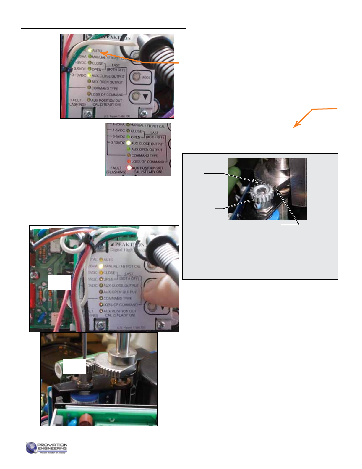
4. Apply line power.
4.A The AUTO green LED will light.
4.B The Red AUX POSITION OUT LED will blink
if there is no control signal.
Begin Calibration
1. Press MODE until MANUAL/FB POT CAL LED is lit.
• You may calibrate this as often as needed but it
may aect the CW and CCW end positions if it
changes.
2. Use ▲ and ▼ or handwheel to position the actuator
to the mid position (i.e. 50% open or 12 mA).
• Blinking amber MANUAL/FB POT CAL light means
you need to adjust the potentiometer position.
3. Feedback Potentiometer Calibration (FB POT
CAL LED is blinking).
3.A Check Potentiometer Gear Engagement as
shown.
3.B Loosen the potentiometer shaft hex screw.
Use a screwdriver to adjust the potentiometer
shaft until the amber LED is steady.
NOTE: The amber LED blinks more rapidly as you
approach the proper mid position. The farther from that
position, the slower the blinkrate.
Potentiometer Gear Engagement
When the actuator is at CW position, make sure that
the potentiometer pinion gear and the camshaft sector
gear do not drive past the point of engagement. If
the sector gear does not have at least 2 full teeth
contacting the potentiometer pinion gear, contact your
distributor for mechanical recalibration instructions.
Hex Screw
Potentiometer
Shaft
4A
4B
1
2
Page 9 of 17 P9/10 HV-N4 Series
Calibrating the proportional control board

FM_P213 HV-PN4-HR (-TS)_Ver M 070721
4. Set Closed (CW) Position (CLOSE LED is lit)
4.A The motor will drive to approximately the 25%
position.
4.B Use the handwheel or the ▲ and ▼ to position
the actuator in the desired CLOSE position (i.e.
4 mA). (You must touch either ▲ or ▼before
the handwheel responds).
4.C Press MODE to conrm setting. This will also
move you to the next user input setting.
4.D This CLOSE position is now set.
4.E If the AUX CLOSE OUTPUT LED is lit, ignore it
4.F OPEN LED is lit.
5. Set Open (CCW) Position (OPEN LED is lit)
5.A The motor will drive to approximately the 75%
position.
5.B Use the handwheel or the ▲ and ▼ to position
the actuator in the desired OPEN position (i.e.
20 mA). (You must touch either ▲ or ▼before
the handwheel responds).
5.C Press MODE to conrm setting. This will also
move you to the next user input setting.
5.D This OPEN position is now set.
5.E If the AUX OPEN OUTPUT LED is lit, ignore it.
5.F AUX CLOSE OUTPUT is lit.
The motor may drive an arbitrary position.
6. Aux Close Output Settings (AUX CLOSE
OUTPUT is lit)
6.A This feature requires an additional optional
board.
6.B Press MODE to skip.
6.C AUX OPEN OUTPUT is lit.
The motor may drive an arbitrary position.
7. Aux Open Output Settings (AUX OPEN OUTPUT
is lit)
7.A This feature requires an additional optional
board.
7.B Press MODE.
7.C COMMAND TYPE LED is lit.
Page 10 of 17 P9/10 HV On/O Series
Calibrating the proportional control board (continued)
FM_P213 HV-PN4-HR (-TS)_Ver M 070721
8. Set Input Signal (COMMAND TYPE LED is lit)
8.A Use ▲ and ▼ to select the command signal
type going into the DHC-100 board from the
column left of the LEDs.
• 4-20mA (factory setting)
• 1-5VDC
• 0-5VDC
• 0-10VDC
8.B Press MODE.
8.C LOSS OF COMMAND LED is lit.
9. Set Loss of Signal (LOSS OF COMMAND LED is lit)
9.A Use ▲ and ▼ to select the fail position on loss
of signal. Select from the column right of the
LEDs.
• CLOSE - fails close (4mA)
• OPEN - fails open (20mA)
• (Both O) - fails in place (default)
9.B Press MODE.
9.C AUX POSITION OUT CAL LED is lit.
The motor may drive an arbitrary position.
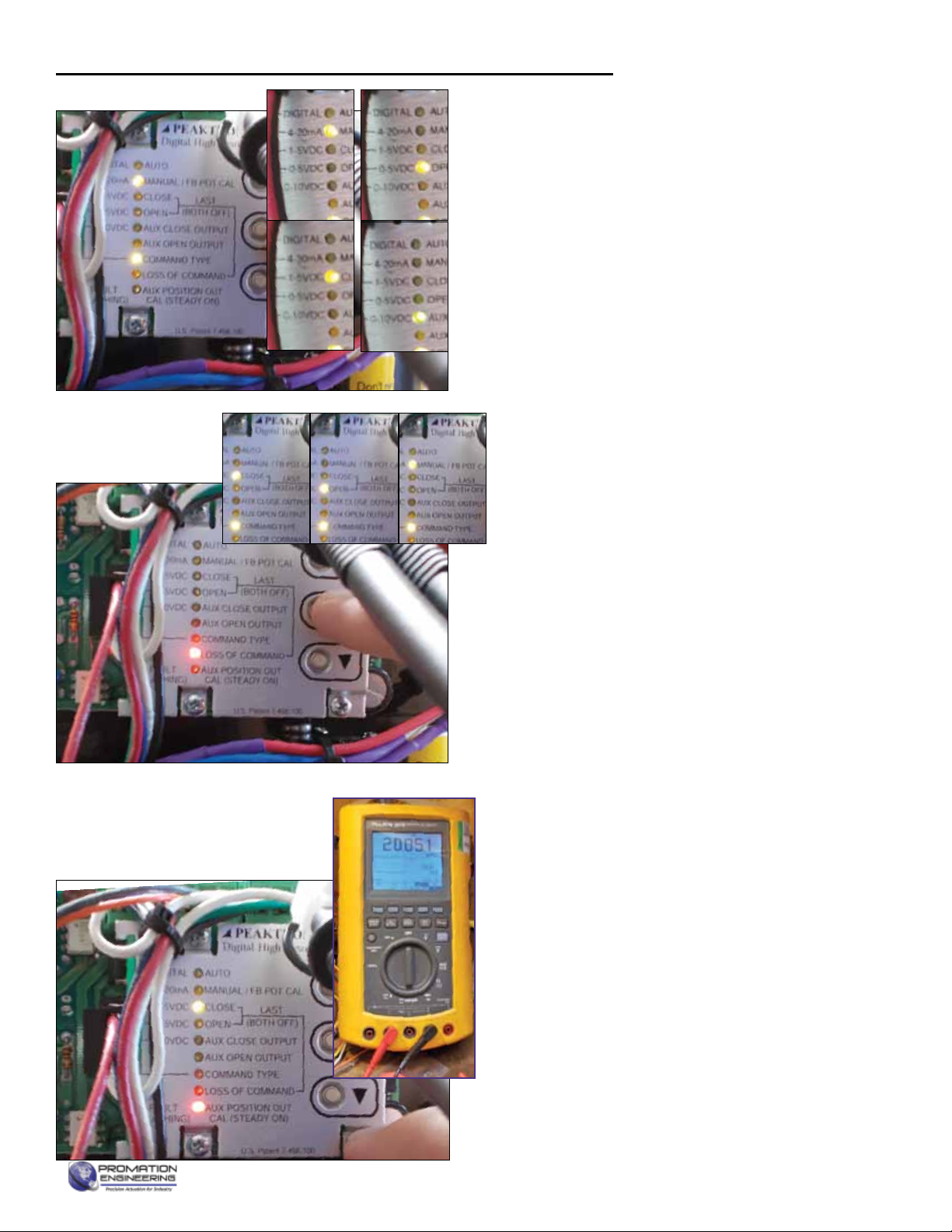
10. Trim the accuracy of the feedback (AUX POSITION
OUT CAL LED is lit)
10.A The position of the actuator is unimportant for
this step.
10.B CLOSE LED should be ashing
10.C Use ▲ and ▼ to adjust the mA feedback for
the CLOSE position (i.e. 4.00mA). Read using
a known accurate multimeter.
10.D Press MODE to conrm setting.
10.E OPEN LED should be ashing
10.F Use ▲ and ▼ to adjust the mA feedback for the
OPEN position (i.e. 20.000mA). This isread on
a known accurate multimeter.
10.G Press MODE to conrm setting, AUTO LED is lit.
Page 11 of 17 P9/10 HV-N4 Series
Calibrating the proportional control board (continued)
FM_P213 HV-PN4-HR (-TS)_Ver M 070721
18. AUTO LED is lit. The actuator is now responding to the
4-20mA signal.
19. Calibration is complete.
20. Reinstall mechanical stop screws.
20.A CCW Stop - drive to the OPEN position and power
down actuator.
• With handwheel, drive more open until you hear the
SW2 switch make.
• Drive the handwheel 1/2 turn more OPEN.
• Use wrench and hex key to install the CCW Stop
screw on the stop boss.
• With the handwheel, insure the end stop is
approximately 1/2 handwheel turn after the SW2
switch makes.
20.B CW Stop - drive to the CLOSE position and power
down actuator.
• With handwheel, drive more close until you hear the
SW1 switch make.
• Drive the handwheel 1/2 turn more CLOSE.
• Use wrench and hex key to install the CW Stop
screw on the stop boss.With the handwheel, insure
the end stop is approximately 1/2 handwheel turn
after the SW1 switch makes.
Page 12 of 17 P9/10 HV On/O Series
Complete Calibration
FM_P213 HV-PN4-HR (-TS)_Ver M 070721
Conrm Controller End of Travel
1. Generate a 4mA control signal and drive the actuator to
its fully CLOSED position.
1.A Evaluate actuator position and feedback values.
1.B If adjustments are needed, reenter the Calibration
Menu.
1.C If red AUX POSITION OUT LED is lit see step 4.
2. Generate a 20mA control signal and drive the actuator to
its fully OPEN position.
2.A Evaluate actuator position and feedback values.
2.B If adjustments are needed, reenter the Calibration
Menu.
2.C If red AUX POSITION OUT LED is lit see step 4.
3. Any changes to the potentiometer will require you to
recalibrate the actuator.
4. IF THE RED AUX POSITION OUT LED IS LIT:
4.A First check the 4-20mA SIGNAL for power.
4.B Next check to see if SW1 or SW2 are made. This
indicates that a Switch is set inside the range 0-90°.
They must be set outside that range by only 1-2° so
as to not adversely aect calibration.
4.C If you need to adjust cams you must review the
4mA and 20mA positions.
Page 13 of 17 P9/10 HV-N4 Series

FM_P213 HV-PN4-HR (-TS)_Ver M 070721
Page 14 of 17 P9/10 HV On/O Series
1
1
2
2
A A
B B
Drawn By
Finish
Promation Engineering Inc.
16138 Flight Path Drive
Brooksville, Fl 34604
Phone: 352-544-8436
Fax: 352-544-8439
This Document is the property of ProMation Engineering,
Inc. Distribution of this document without the written
consent of the owner is Strictly forbidden.
Failure to comply will incur a liability for Damages.
Checked By
4/8/2015
P9~P12 Dim Data
Rev.
F
NO SCALE Sheet Number: 1
Material
ProMation Engineering, Inc.
KHL
KHL
2/10/2014
P9_12 F16 R75 DimData.idw
Created:
Last Checked:
Part No.
Dwg. Name
Dimensional Data for P9~P12 Actuators (w/ or w/o -TS)
Engineering Change Notice
Change Date Description Name
02.10.2014 New Document KHL
04.15.2014 Added tolerance on drive coupling data KHL
04.23.2014 Lengthened handwheel, edited drawing to include TS text KHL
07.14.2014 Corrected tolerance on 75mm Drive Coupling KHL
10.07.2014 Pushed output diameter dimension to three decimal places, added keyway dimension KHL
04.08.2015 Added Isometric view of Drive Coupling and "Depth" tag for clarity KHL
REV
A
B
C
D
E
F
Dimensional Tolerances (Unless Otherwise Noted):
X.X ±.3 [X.XX ±.01]
X.XX ±.13 [X.XXX ±.005]
ALL TOLERANCE FEATURES IN mm
458 mm
18.0 in 285 mm
11.2 in
402 mm
15.8 in
262 mm
10.3 in
398 mm
15.7 in
220 mm
8.7 in
552 mm
21.7 in
Add 254mm
[10"] to allow
for cover
removal
165 mm
6.5 in
BHC
(4) M20x2.5
30mm
1.2"
F16 ISO Flange
75.00 mm
2.953 in
218 mm
8.6 in
184 mm
7.2 in
(2) 3/4" NPT
EMT Entry
Drive Coupling Fabrication Data
12.00 mm
.472 in
10.00 mm
.394 in
75.00
-.13
.00
+mm
2.953 -0.005
0.000
+in
100.00 mm
3.937 in
Depth
31.50 mm
1.240 in KEY
12.00 mm
.472 in
Keyway
P9/10 Series Dimensional Data
Mechanical Data
FM_P213 HV-PN4-HR (-TS)_Ver M 070721
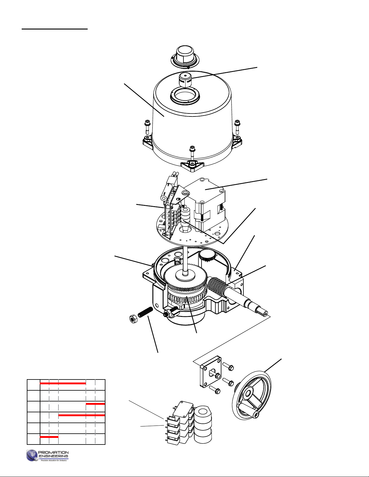
P Series Exploded View
(P2/3-120N4 unit is shown)
Easily distinguishable
yellow/red position
indicator
Worm Drive
Heavy Duty
Drive Motor
Easily accessible
switch & cam stacks
Modular
Control
Cards
Clutchless
Override
Handwheel
Aluminum Casting
NEMA 4X Protection
Aluminum Casting
NEMA 4X Protection
Epicyclic Gearing
Mechanical Stop
Screws (2)
NEMA 4X
Cover Seal
Switch sequencing data is provided in the table
below to show the change-of-state points during
the rotation of the actuator from CCW to CW
and back again. The red bar shows when that
terminal makes with its respective common.
Switches 1 and 2 are set at the factory and
should NOT be changed. The INCLUDED
auxiliary switches SW3 & SW4 are for terminals
7 thru 12 and those set points may be modi ed
if need be. When so optioned, SW5 & SW6
auxiliary switches are initially set to function
the same as auxiliary switches SW3 & SW4.
Switch Logic Map and
Switch/Cam Arrangement
12
11
10
9
8
7
SW3 CW AUX
(Factory Set - Adj)
SW4 CCW AUX
(Factory Set - Adj)
}
}
Closed Switch Common
Open Switch Common
Open
Closed
Not Open
-5°0°
CW CCW
85°
5°90°95°
Not Closed
}
Used by
Controller
Page 15 of 17 P9/10 HV-N4 Series
Mechanical Data

FM_P213 HV-PN4-HR (-TS)_Ver M 070721
WARNING! Do NOT
adjust the torque
switch cam settings.
This will VOID the
warranty.
After completing all mounting and wiring procedures and main power is available, it is now possible to commission
the actuator.
1. Utilize the handwheel to rotate the actuator and damper, valve or other connected device through its full travel from
full CW to full CCW and back again to check for any possible interference. Do NOT utilize any mechanical advantage
devices to rotate the handwheel (pipes, wrenches, extension bars, etc.).
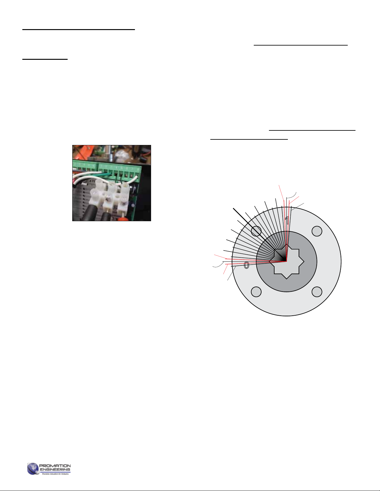
2. Manually position the actuator to its mid-stroke position.
3. Make certain the 3 wire orange plug is fully seated on the 3-pin receptacle on the switch board.
4. Apply correct power to the unit.
5. Measure correct power on terminals 1 and 2 on the switch board.
6. Measure correct power on the two heater terminals on the switch board.
7. Command the eld device to generate a CCW signal. The actuator rotates in a CCW direction (as viewed from above).
8. Actuator will stop when it reaches it’s full CCW position.
9. Command the eld device to generate a CW signal. The actuator rotates in a CW direction (as viewed from above).
10. Actuator will stop when it reaches it’s full CW position.
11. Generate a mid-position signal at the eld device to move the actuator o its full CW trip position.
12. Actuators with no -TS options are now commissioned and operational. See below for additional -TS steps.
Commissioning
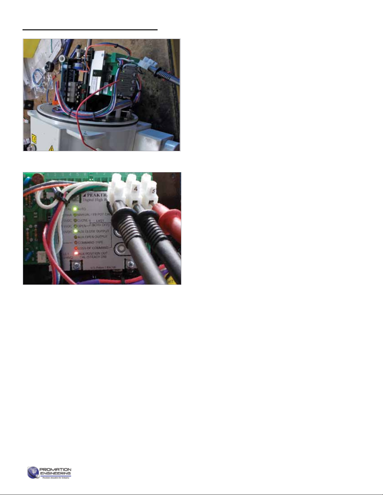
Test Torque Switch functions
1. Generate a 4mA or 20mA control signal and let the actuator
drive towards that CW or CCW position.
2. As the motor is running, simulate a torque switch event:
Depress the top or bottom torque switch and hold it (one
will immediately stop the motor).
3. Release the torque switch.
4. Test recovery from the torque switch event.
• Move the handwheel 2° in either direction
• Signal the motor to drive.
5. Repeat steps 5.A through 5.D in the opposite direction
(20mA or 4mA) to test the opposing direction torque switch
functionality.
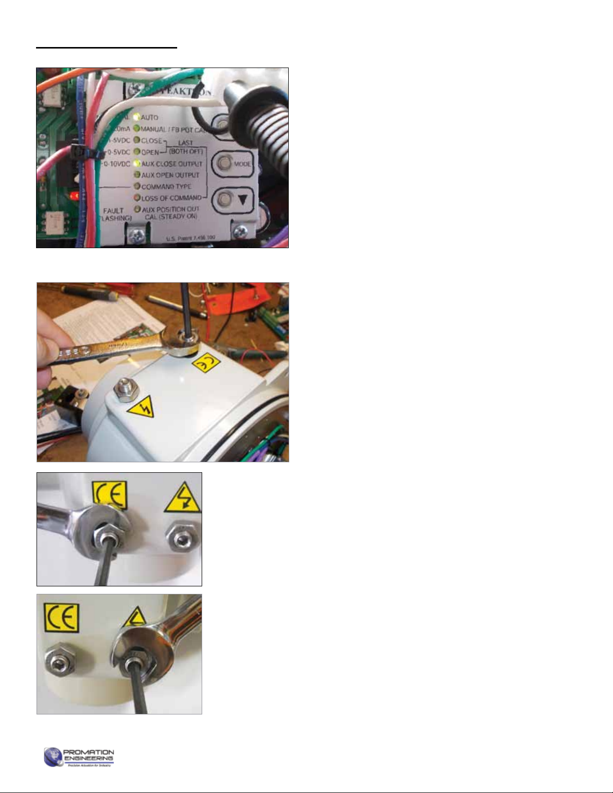
Testing Torque Switch Electrical Operation
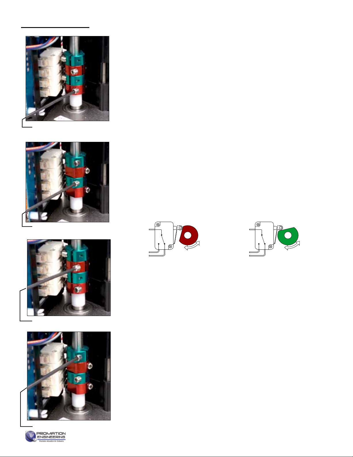
TS units incorporate a torque overload protection system. In NORMAL
operating mode, the torque switch drive cam is in this position:
Torque Switch cams shown in the NORMAL
operating position (No high torque situations)
High Torque Cam
(bottom) for CCW
Output Drive Rotation
High Torque Cam
(top) for CW Output
Drive Rotation
High Torque Switch
(top) for CW Output
Drive Rotation
High Torque Switch
(bottom) for CCW
Output Drive Rotation
Commissioning for TS units
Page 16 of 17 P9/10 HV On/O Series

FM_P213 HV-PN4-HR (-TS)_Ver M 070721
Torque Switch cams shown with the lower
cam in a TRIPPED position (high torque in the
CCW Output Drive Direction)
High Torque Cam
(bottom) for CCW
Output Drive Rotation
High Torque Cam
(top) for CW Output
Drive Rotation
High Torque Switch
(bottom) for CCW
Output Drive Rotation
High Torque Switch
(top) for CW Output
Drive Rotation
WARNING! Do NOT
adjust the torque
switch cam settings.
This will VOID the
warranty.
Test Torque Switch CCW Mechanical Operation
1. Rotate the manual override handwheel in a CCW direction to continue to drive the output drive in a CCW direction until
the drive system reaches the end of its MECHANICAL travel either by coming into contact with the mechanical stop
screw OR it reaches the end of the valve (or damper) travel. This is indicative of an increasing force required to rotate
the handwheel.
2. At this point the torque switch cam shaft starts to rotate in a CW direction. (There is no need to continue to rotate the
handwheel further in the CCW direction, the torque switch cam shaft would continue to rotate in the CW direction until
the LOWER cam trips the LOWER high torque switch).
3. At this point, stop rotating the handwheel as you’ve simulated reaching the electrical drive limit of the actuator under
excessively high torque situations in the CCW output drive direction.
Torque Switch cams shown with the upper
cam in a TRIPPED position (high torque in
the CW Output Drive Direction)
High Torque Cam
(bottom) for CCW
Output Drive Rotation
High Torque Cam
(top) for CW Output
Drive Rotation
High Torque Switch
(bottom) for CCW
Output Drive Rotation
High Torque Switch
(top) for CW Output
Drive Rotation
WARNING! Do NOT
adjust the torque
switch cam settings.
This will VOID the
warranty.
Test Torque Switch CW Mechanical Operation
1. Rotate the manual override handwheel in a CW direction to continue to drive the output drive in a CW direction until
the drive system reaches the end of its MECHANICAL travel either by coming into contact with the mechanical stop
screw OR it reaches the end of the valve (or damper) travel. This is indicative of an increasing force required to rotate
the handwheel.
2. At this point the torque switch cam shaft starts to rotate in a CCW direction. (There is no need to continue to rotate the
handwheel further in the CW direction, the torque switch cam shaft would continue to rotate in the CCW direction until
the UPPER cam trips the UPPER high torque switch).
3. At this point, stop rotating the handwheel as you’ve simulated reaching the electrical drive limit of the actuator under
excessively high torque situations in the CW output drive direction.
Commissioning for TS units (continued)
4. Generate a mid-position signal at the eld device to move the actuator o its full CW trip position.
5. Actuator is now commissioned and operational.
Page 17 of 17 P9/10 HV-N4 Series

ENGINEERING CHANGE NOTICE
REV DATE DESCRIPTION EDITOR REVIEW
BY
RELEASE
DATE
H 091614
New Document, level H standards using existing P1, P23
VN4 IOMs. Pg 4 has, on W.D., colored LEDs and white tags
covering wire colors. Commissioning is a hybrid of VN4 and
-TS Commissioning pages.
TJM KHL 091614
I 10.13.14 Relink DimData TJM KHL
IOM Template Master.indd
Page B of B P2/3 Series HV-TS AdVanced Proportional Control
FM_P213 HV-PN4-HR (-TS)_Ver M 070721
This manual suits for next models
3
Table of contents
Other Promation Engineering Industrial Equipment manuals


