manuals.online logo
Brands
  1. Home
  2. •
  3. Brands
  4. •
  5. Tyco Electronics
  6. •
  7. Industrial Equipment
  8. •
  9. Tyco Electronics 1752786-1 User manual

Tyco Electronics 1752786-1 User manual

Instruction Sheet
Hydraulic Crimping 408--8958
LOC B
1of 3
E2010 Tyco Electronics Corporation, Berwyn, PA
All Rights Reserved
TE logo and Tyco Electronics are trademarks.
*Trademark. Other product names, logos, or company names might be trademarks of their respective owners.
TOOLING ASSISTANCE CENTER 1--800--722--1111
PRODUCT INFORMATION 1--800--522--6752
This controlled document is subject to change.
For latest revision and Regional Customer Service,
visit our website at www.tycoelectronics.com
10 MAR 10 Rev BHead 1752786- 1
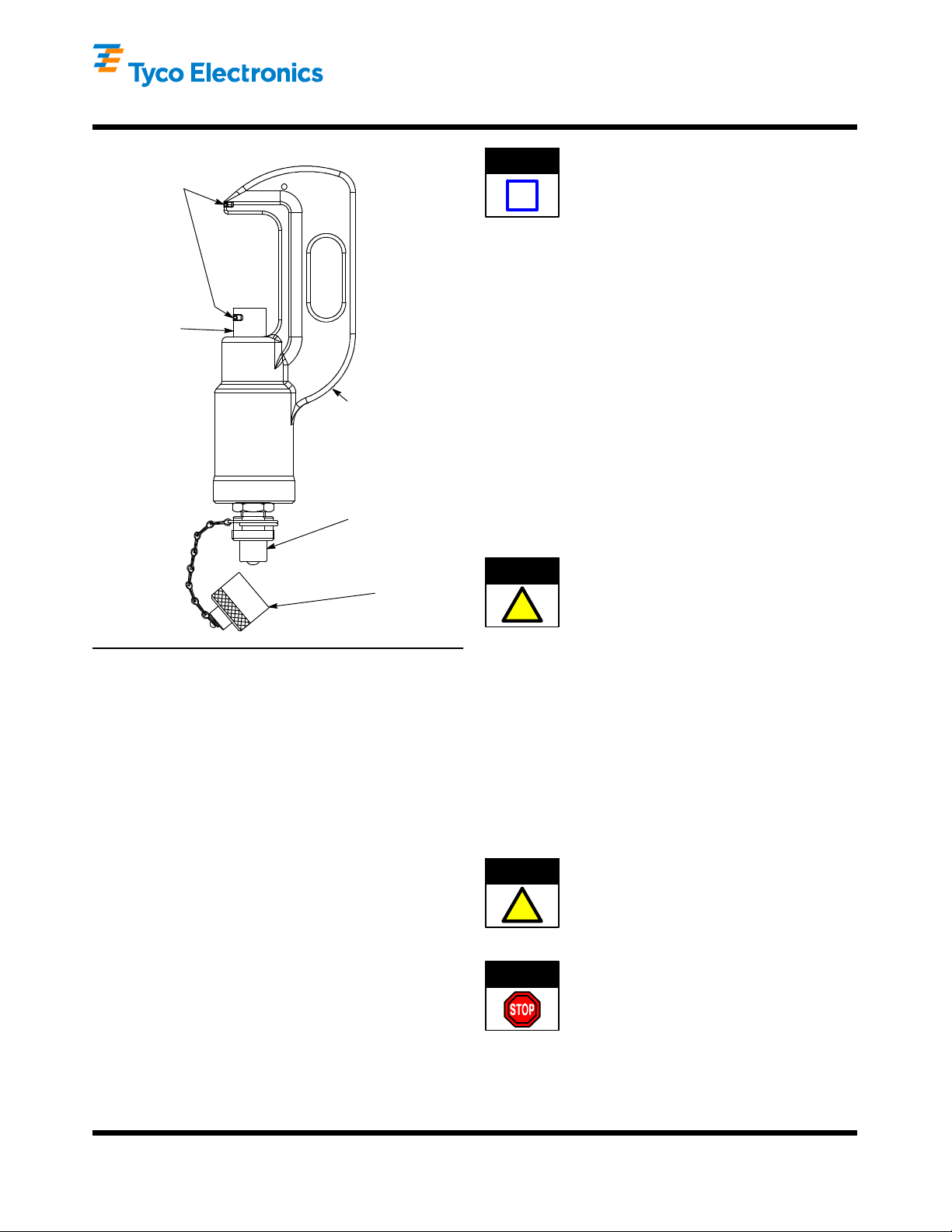
Figure 1
Dust Cap
Quick--Disconnect
Coupling
Crimping
Head
(“C”--Head)
Piston (Fully
Extended)
Lock Screws
1. INTRODUCTION
This instruction sheet provides operation and
maintenance instructions for Hydraulic Crimping Head
1752786--1. See Figure 1.
The crimping head accepts interchangeable die sets
for a variety of terminals and splices for large wire
sizes --4/0 through 1000 MCM range. Refer to the
instructions packaged with the specific die sets for
compatible products, wire ranges, strip dimensions,
and application procedures.
The crimping head is designed and recommended for
use with the Foot Hydraulic Pump 1583659--1; Hand
Hydraulic Pump 1583661--1; or the Electric Hydraulic
Pump 1804700--1 (110Vac) or 1804700--2 (220 Vac).
Read these instructions and all applicable references
before inserting any die set assemblies and crimping
any terminals or splices.
Dimensions on this sheet are in metric units [with
U.S. customary units in brackets]. Figures and
illustrations are for reference only and are not
drawn to scale.
Reasons for reissue of this instruction sheet are
provided in Section 7, REVISION SUMMARY.
2. DESCRIPTION (Figure 1)
Main components of Hydraulic Crimping Head
1752786--1 include a “C”--head, which houses the
stationary die, a cylinder which contains the head’s
hydraulic chamber, a piston (ram) which holds and
controls the moving die, and a quick--disconnect
coupling (cylinder half) which mates with the coupling
on the hose to release or supply pressure. A dust cap
covers the quick--disconnect coupling.
3. INSTALLATION
3.1. Head Installation
Prior to installing the head, ensure that the pump
and hose being used are working properly, and
are adjusted to and rated at 68948 kPa
[10,000 psi]. An incorrectly adjusted or rated
pump/hose could result in severe tooling
damage, as well as personal injury.
1. Release the hydraulic pressure to the hose.
Disconnect electric power unit from power supply.
2. Remove protective dust caps.
3. Thoroughly clean the coupling on the
pump/hose and the coupling on the crimping head.
4. Mate both quick--disconnect couplings and
tighten the collar of the coupler assembly on the
hose.
Oil flow must be unobstructed between the power
unit and the crimping head. Ensure that all
couplings are fully mated and tightened.
If a crimping head must be removed after the
power unit was in operation, be sure to release
the pressure in the hydraulic system. When using
Hydraulic Power Unit 1804700--[ ],
DISCONNECT THE POWER UNIT FROM THE
POWER SUPPLY. When using Hydraulic Foot
Pump 1583659--1 or Hydraulic Hand Tool
1583661--1, depress the pressure release pedal
to release pressure.
ORIGINAL INSTRUCTIONS
NOTE
i
CAUTION
!
CAUTION
!
DANGER
408- 8958
Hydraulic Crimping Head 1752786- 1
Rev B2 of 3 Tyco Electronics Corporation
Lock Screw
Stationary Die
Moving Die
Flat on Shank
Faces Lock Screw
Figure 2
3.2. Die Installation/Removal
A. Die Installation
To avoid personal injury, do NOT accidentally
depress the footswitch or handle control when
installing or removing dies.
Operating the head WITHOUT the crimping dies
installed will damage the “C”--Head or ram.
1. Back off the set--screws in the head and ram
(ram must be advanced to gain access to the
set--screw). Refer to Figure 2.
2. Insert dies in the head and ram, ensuring that
the “flats” on the die shanks are facing the
set--screws (see Figure 2).
3. Tighten the set--screws.
4. Slowly close the dies to ensure proper
alignment.
5. Complete the cycle and return the ram to the
“down” position.
B. Die Removal
To avoid personal injury, do NOT accidentally
depress the footswitch or handle control when
installing or removing dies.
Operating the head WITHOUT the crimping dies
installed will damage the “C”--Head or ram.
1. Back off the set--screw in the C--Head and
remove the stationary die.
2. Raise the ram slightly to gain access to the
set--screw in the piston (ram).
3. Back off the set--screw in the piston (ram) and
remove the moving die.
4. CRIMPING PROCEDURE
The following procedure provides only general
information concerning crimping. Refer to the
instructions packaged with the dies and power unit for
detailed information, including wire stripping
dimensions and instructions for positioning terminals
and splices in the dies.
1. Insert terminal or splice in the stationary die
according to the instructions packaged with the
dies.
2. Activate the power unit to advance the dies and
hold the terminal or splice in place.
3. Insert stripped wire into the terminal or splice.
4. Activate the power unit to complete the crimp.
5. INSPECTION/MAINTENANCE
Make sure hydraulic pressure is released and
power supply is disconnected before following
inspection and maintenance procedures, unless
otherwise specified in the procedure.
Each crimping head is assembled and inspected
before shipment. It is recommended that the crimping
head be inspected immediately upon its arrival at your
facility, and at regularly scheduled intervals, to ensure
that the crimping head has not been damaged during
handling. Frequency of inspection depends upon the
following:
SCare, amount of use, and handling of the head;
SType and size of products crimped;
SDegree of operator skill; and
SEnvironmental conditions.
Once a year, or every 7,500 cycles (whichever comes
first), the hydraulic head should be returned to Tyco
Electronics for magnetic particle inspection.
DANGER
CAUTION
!
DANGER
CAUTION
!
DANGER
408- 8958
Hydraulic Crimping Head 1752786- 1
3of 3Rev BTyco Electronics Corporation
Additionally, inspect and service the head every
month or 1,000 cycles, whichever comes first.
Inspect the metal surfaces for nicks, cracks,
scratches, and excessive wear, especially where
sliding contact occurs. Refer to Figure 3. Inspect for
cracks especially at the corners of the “C”--head and
around the top of the cylinder.
5.1. Cleaning
Remove accumulations of dirt and grease on the
crimping head, especially in areas where dies are
installed and terminals are crimped. Clean the entire
head frequently with a clean, lint--free cloth.
Figure 3
Check
These
Areas for
Cracks
5.2. Crimping Head Check- Out Procedure
If the ram fails to retract after completion of a
crimping cycle, the cause may be in the crimping
head. To determine whether or not the trouble is in
the crimping head, release pressure in the power unit.
If the ram retracts, the trouble is not in the crimping
head. If ram does NOT retract, refer to Section 6,
RETURN/REPAIR.
Replacement parts are listed in Figure 4.
6. RETURN/REPAIR
Order replacement parts through your Tyco
Electronics Representative, or call 1--800--526--5142,
or send a facsimile of your purchase order to
1--717--986--7605, or write to:
CUSTOMER SERVICE (38--35)
TYCO ELECTRONICS CORPORATION
PO BOX 3608
HARRISBURG PA 17105--3608
Crimping heads may also be returned for evaluation
and repair. For tool repair service, contact a Tyco
Electronics Representative at 1--800--526--5136.
1
2
ITEM
NO.
PART
NO. DESCRIPTION QTY
121013--4 SCREW, Socket, Self--Locking 2
2311470--1 QUICK--COUPLER, Male 1
Figure 4
7. REVISION SUMMARY
SAdded “Original Instructions” statement

Other Tyco Electronics Industrial Equipment manuals

Tyco Electronics AMP-TAPETRONIC 69875 Reference guide

Tyco Electronics

Tyco Electronics AMP-TAPETRONIC 69875 Reference guide

Tyco Electronics FOSC-600 C User manual

Tyco Electronics

Tyco Electronics FOSC-600 C User manual

Tyco Electronics AMP 58246–1 User manual

Tyco Electronics

Tyco Electronics AMP 58246–1 User manual

Tyco Electronics CS 200 Reference guide

Tyco Electronics

Tyco Electronics CS 200 Reference guide

Tyco Electronics EPP-0001-INT-4/10 User manual

Tyco Electronics

Tyco Electronics EPP-0001-INT-4/10 User manual

Tyco Electronics AMP NETCONNECT MRJ21 User manual

Tyco Electronics

Tyco Electronics AMP NETCONNECT MRJ21 User manual

Tyco Electronics DT-3000 Reference guide

Tyco Electronics

Tyco Electronics DT-3000 Reference guide

Tyco Electronics AMP-O-LECTRIC 690675-2 User manual

Tyco Electronics

Tyco Electronics AMP-O-LECTRIC 690675-2 User manual

Tyco Electronics KILOVAC EV200 Series User manual

Tyco Electronics

Tyco Electronics KILOVAC EV200 Series User manual

Popular Industrial Equipment manuals by other brands

Jäger Z62-K360.12 S4A manual

Jäger

Jäger Z62-K360.12 S4A manual

Kobelt 5020-M Series Owner's Operation, Installation & Maintenance Manual

Kobelt

Kobelt 5020-M Series Owner's Operation, Installation & Maintenance Manual

Avtron LPV600 manual

Avtron

Avtron LPV600 manual

Rondo Manomat operating manual

Rondo

Rondo Manomat operating manual

Westinghouse SJA Supplementary instructions

Westinghouse

Westinghouse SJA Supplementary instructions

ABB Relion SMU615 Applications manual

ABB

ABB Relion SMU615 Applications manual

Wilo DrainLift SANI CUT-M Installation and operating instructions

Wilo

Wilo DrainLift SANI CUT-M Installation and operating instructions

GÜDE GBF 550 Translation of the original instructions

GÜDE

GÜDE GBF 550 Translation of the original instructions

probst FTZ-UNI-50 operating instructions

probst

probst FTZ-UNI-50 operating instructions

Tronair JP30 Operation & service manual

Tronair

Tronair JP30 Operation & service manual

Global BEAT-Tr user manual

Global

Global BEAT-Tr user manual

Axminster PROFESSIONAL AP200SM Original instructions

Axminster

Axminster PROFESSIONAL AP200SM Original instructions

Neco STIR-RITE III Owner's/operator's manual

Neco

Neco STIR-RITE III Owner's/operator's manual

Ecoflam GT-D1-GBLE055-RP15-MAXGAS40-120 manual

Ecoflam

Ecoflam GT-D1-GBLE055-RP15-MAXGAS40-120 manual

Atlantic Boilers RS TURBOFLOW DN 32 S020+ operating & maintenance manual

Atlantic Boilers

Atlantic Boilers RS TURBOFLOW DN 32 S020+ operating & maintenance manual

Regulus HSK 350 K P-B Installation and operation manual

Regulus

Regulus HSK 350 K P-B Installation and operation manual

Aerotech ANT180-160-L Hardware manual

Aerotech

Aerotech ANT180-160-L Hardware manual

FRIEDHELM LOH Rittal 8100.730 Assembly instructions

FRIEDHELM LOH

FRIEDHELM LOH Rittal 8100.730 Assembly instructions

manuals.online logo
manuals.online logoBrands
  • About & Mission
  • Contact us
  • Privacy Policy
  • Terms and Conditions

Copyright 2025 Manuals.Online. All Rights Reserved.