Promeba PB-410 Series User manual
USER GUIDE
BENCH // PB-410 SERIES
Review 09/19


USER GUIDE // BENCH PB-410 SERIES
Review 09/19
3
01 INTRODUCTION
01.1 Using this manual 05
01.2 Technical data sheet 06
02 INSTALLATION
02.1 Transport and unpacking 11
02.2 Anchorage points 12
03 OPERATION
03.1 Commands 15
03.2 Elements of the manual system 19
03.3 Loading and unloading operation 21
03.4 Scoop stretcher fastening 22
03.5 Tensors 23
03.6 Loading angle setting 24
04 MOUNTING AND COMPONENTS
04.1 Main exploded view SERIE PB-410 25
04.2 Top platform exploded view PB-410 • PB-410/3 26
04.3 Top platform bill of materials PB-410 • PB-410/3 27
04.4 Top platform exploded view PB-410/4 28
04.5 Top platform bill of materials PB-410/4 29
04.6 Top platform exploded view PB-410/5 30
04.7 Top platform bill of materials PB-410/5 31
04.8 Base platform exploded view SERIE PB-410 32
04.9 Base platform bill of materials SERIE PB-410 33
04.10 Base platform mounting plates exploded view SERIE PB-410 34
04.11 Base platform mounting plates bill of materials SERIE PB-410 35
04.12 Base platform exploded view PB-410 • PB-410/4 • PB-410/5 36
04.13 Base platform bill of materials PB-410 • PB-410/4 • PB-410/5 37
04.14 Base platform exploded view PB-410/3 38
04.15 Base platform bill of materials PB-410/3 39
05 GENERAL MAINTENANCE 40
06 LEGAL NOTICES 41
07 PRODUCT WARRANTY 42
CONTENTS
MODEL PB410
WITH CAVITY
FOR SCOOP STRETCHER
MODEL PB410/3
WITH LONGITUDINAL
SLIDING PLATFORM
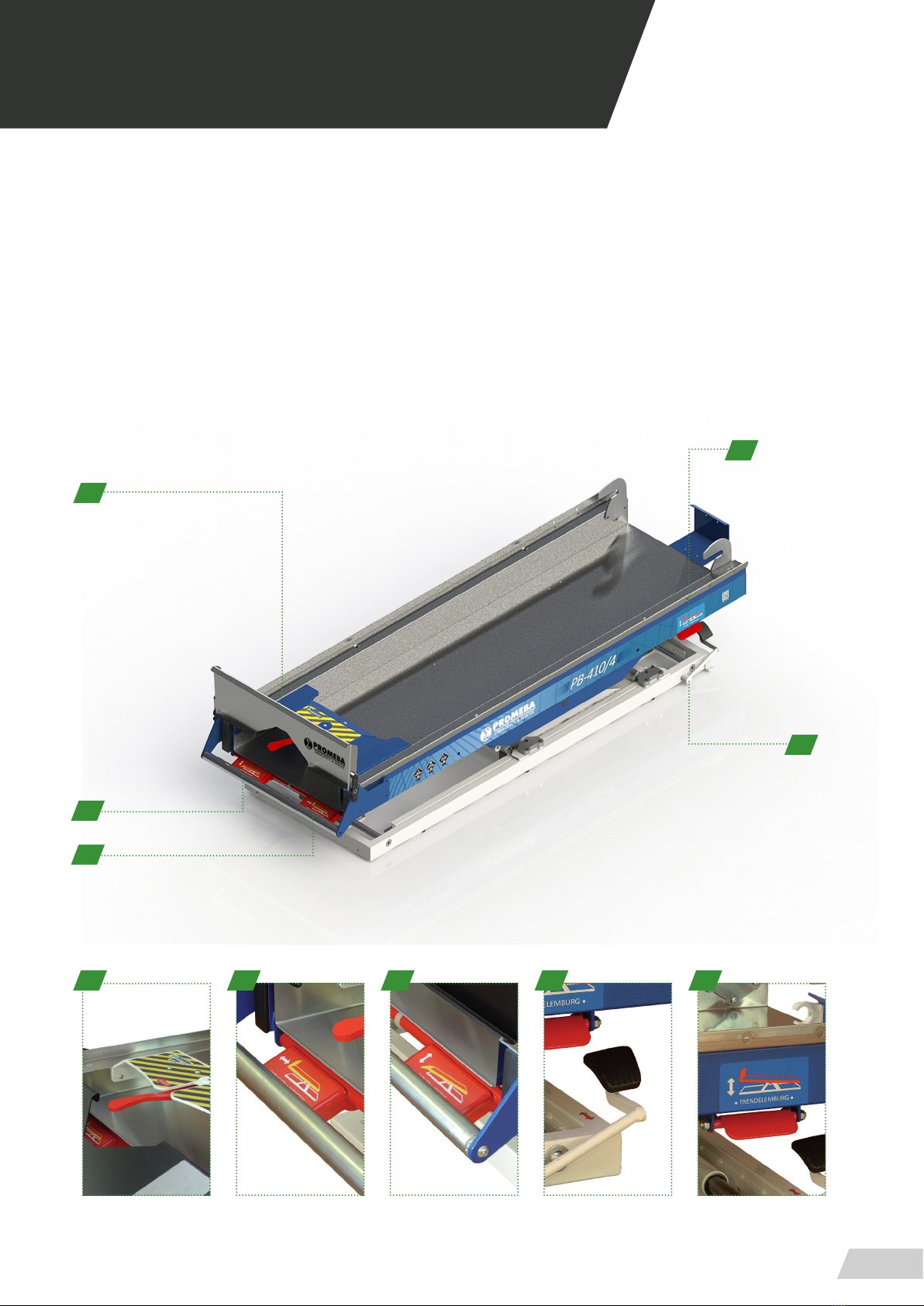
MODEL PB410/4
CAVITY FOR SCOOP STRETCHER
AND SPINE BOARD
MODEL PB410/5
WITH FLAT UPPER TRAY


USER GUIDE // BENCH PB-410 SERIES
Review 09/19
5
01 INTRODUCTION
01.1 Using this manual
This manual provides using and maintenance instruc-
tions of the product, as well as the way of xing minor
faults that could appear.
It is recommended before the operation of the product
to read carefully this manual in order to avoid damages
caused by a misuse.
Do not lose this document, it should be accessible to
any doubt that could appear by medical personnel.
Remember that a good use and maintenance are ne-
cessary for the proper operation of the product.
Each product incorporates an identication sticker with
the serial number and the model. Keep these numbers
so that they can be indicated to the dealer if necessary.
USER GUIDE // BENCH PB-410 SERIES
Review 09/19
6
01 INTRODUCTION
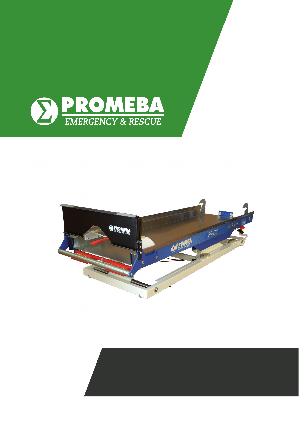
01.2 Technical data sheet
MEASURES AND FEATURES // PB 410
LENGHT 1800 mm TRENDELEMBURG -10º / +10º
WIDTH 595 mm HEIGHT LOADING ± 100 mm
HEIGHT 315 mm SIDE MOVEMENT 300 mm
WEIGHT 83 Kg MAX. LOAD 220 Kg
1800
315
595
USER GUIDE // BENCH PB-410 SERIES
Review 09/19
7
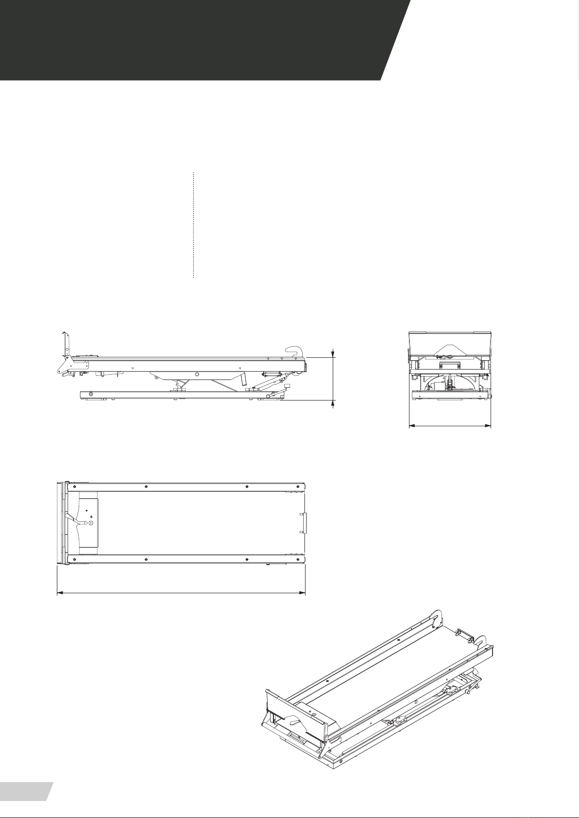
MEASURES AND FEATURES // PB 410/3
LENGHT 1925 mm TRENDELEMBURG -10º / +10º
WIDTH 595 mm HEIGHT LOADING ± 100 mm
HEIGHT 315 mm FRONT / SIDE MOVEMENT 300 mm / 360 mm
WEIGHT 85 Kg MAX. LOAD 220 Kg
01 INTRODUCTION
315
1925
595

USER GUIDE // BENCH PB-410 SERIES
Review 09/19
8
01 INTRODUCTION
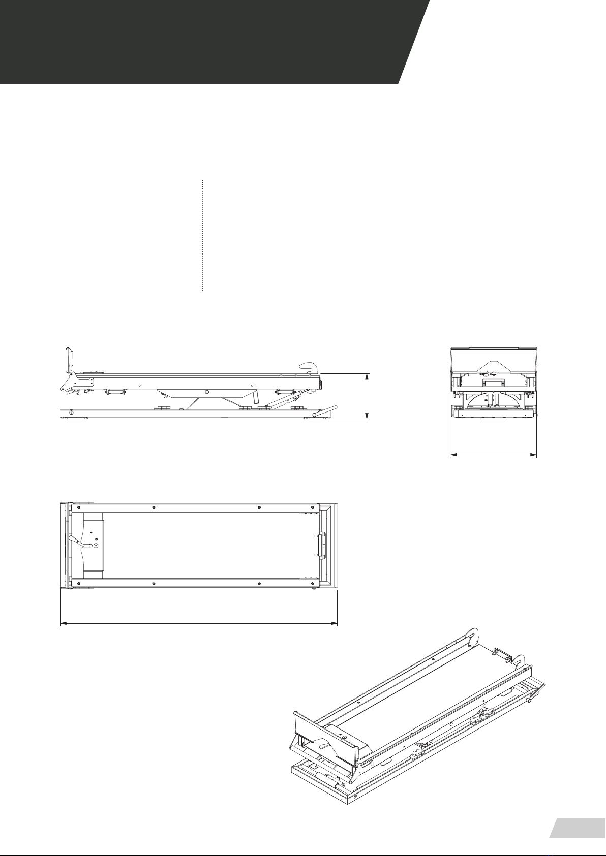
MEASURES AND FEATURES // PB 410/4
LENGHT 1930 mm TRENDELEMBURG -10º / +10º
WIDTH 600 mm HEIGHT LOADING ± 100 mm
HEIGHT 345 mm SIDE MOVEMENT 300 mm
WEIGHT 83 Kg MAX. LOAD 240 Kg
345
1930
600
USER GUIDE // BENCH PB-410 SERIES
Review 09/19
9
01 INTRODUCTION
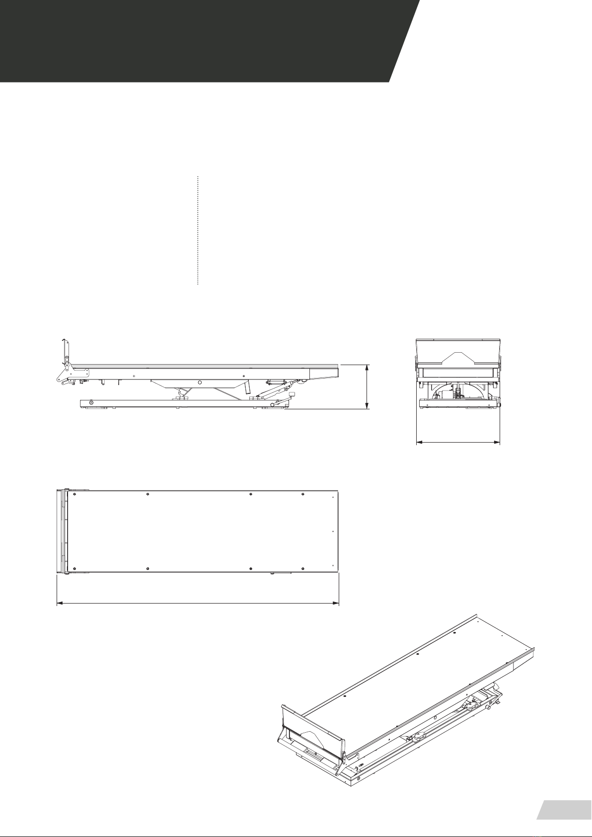
MEASURES AND FEATURES // PB 410/5
LENGHT 2000 mm TRENDELEMBURG -10º / +10º
WIDTH 595 mm HEIGHT LOADING ± 100 mm
HEIGHT 315 mm SIDE MOVEMENT 300 mm
WEIGHT 88 Kg MAX. LOAD 220 Kg
315
2000
595

USER GUIDE // BENCH PB-410 SERIES
Review 09/19
11
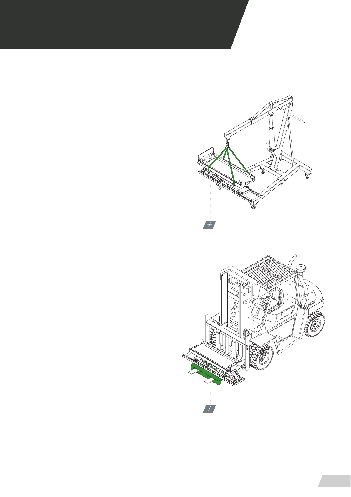
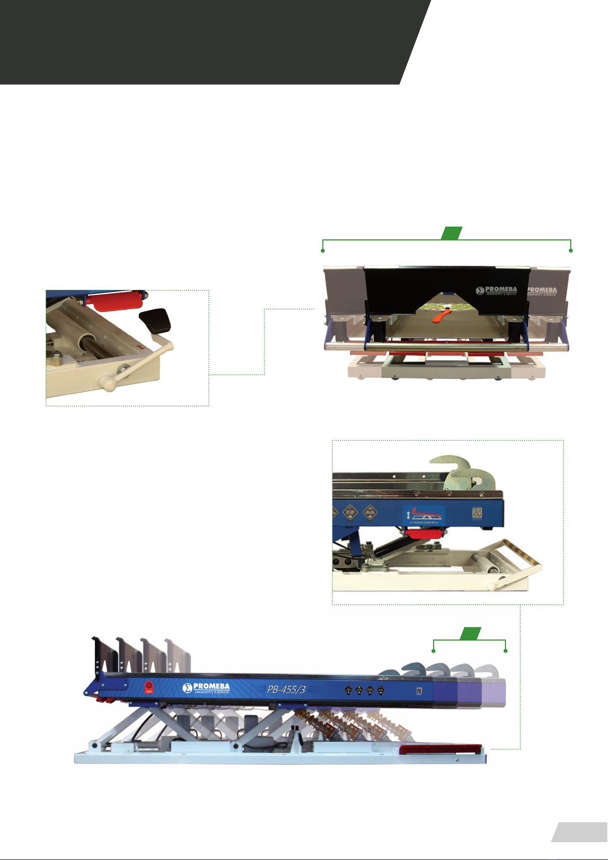
TRANSPORT WITH A CRANE
FIX THE TAPES TO LEVEL THE LOAD WEIGHT
TRANSPORT WITH A FORKLIFT
USE ALWAYS A FLAT SUPPORT SURFACE
02 INSTALLATION
02.1 Transport and unpacking
First carefully remove the packaging to prevent the da-
mage of the outside of the stretcher support.
1. Transport with a crane (high load)
· Thread tapes through the upper platform for its trans-
port (as shown in graphs)
· Transport the load level following all the precepts and
regulations for the transport of suspended loads.
2. Transport with a forklift
· Place a pallet or a at surface under the bench and
transport it transversely.
· Do not load the bench directly on the forklift without
a pallet or a at support surface.
· Do not load the bench longitudinally on the forklift if
a suciently long base is not available.
· Every bench has been thoroughly inspected leaving
the factory. To ensure that it hasn’t been damaged du-
ring the transport, it is requested to carefully examine
the interior and exterior, and in case of nding any da-
mage, communicate immediately to the installer.
· The bench should be levelled for an optimum perfor-
mance.
USER GUIDE // BENCH PB-410 SERIES
Review 09/19
12
02 INSTALLATION
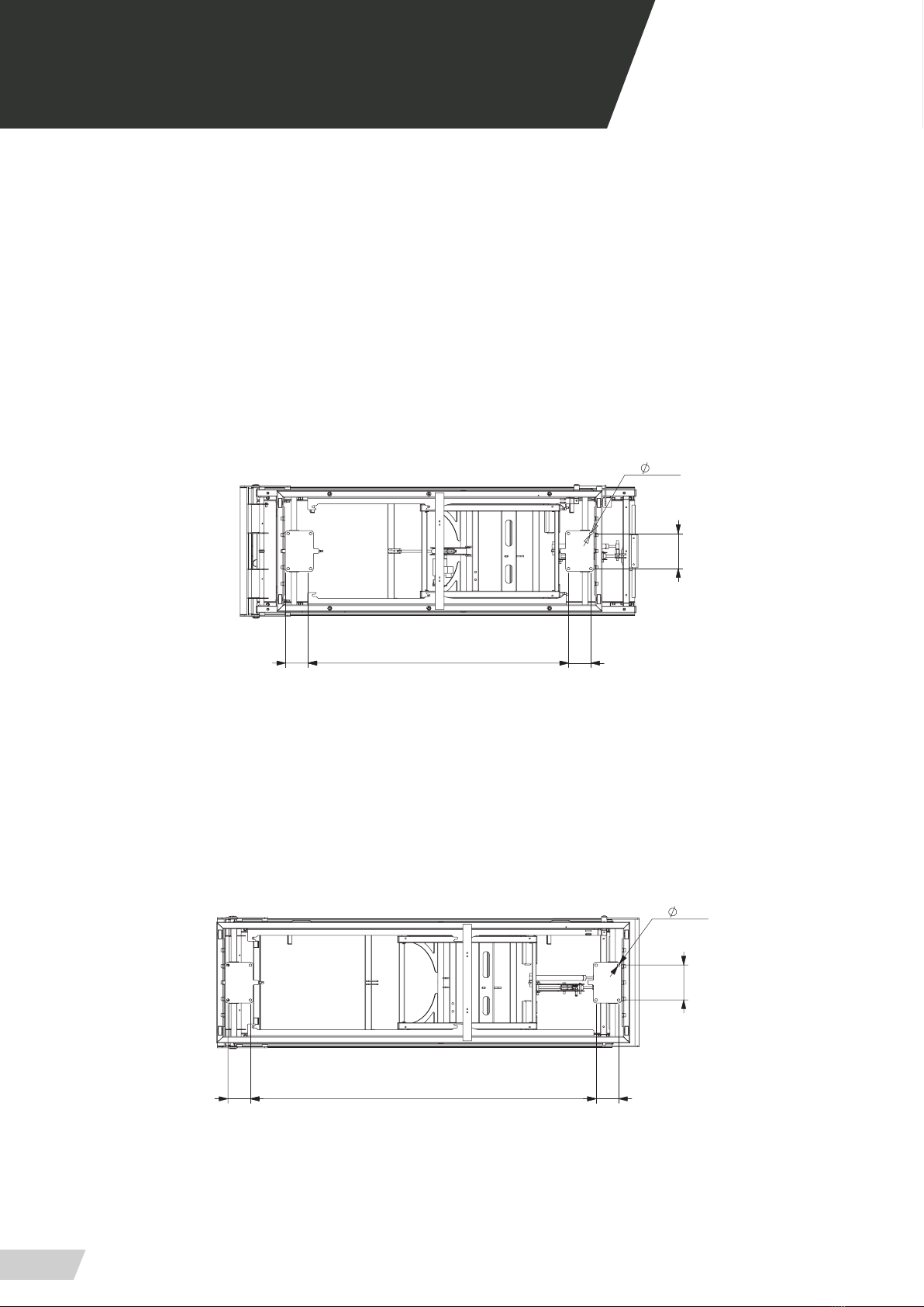
02.2 Anchore points
Before putting the bench into operation, ensure that
each and every anchorage points are placed and
clasped.
ANCHORE FOR BENCH PB410
(8 anchorage points)
ANCHORE FOR BENCH PB410/3
(8 anchorage points)
159
1574 102102
12,5
102
159
1174 102
12,5
USER GUIDE // BENCH PB-410 SERIES
Review 09/19
13
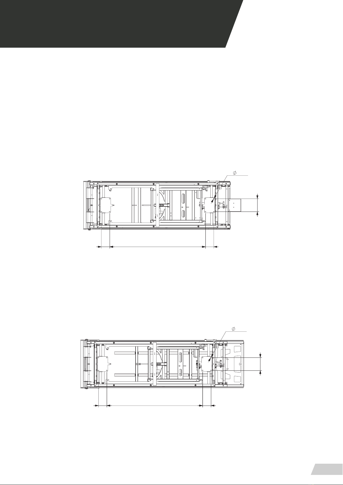
02 INSTALLATION
ANCHORE FOR BENCH PB410/4
(8 anchorage points)
ANCHORE FOR BENCH PB410/5
(8 anchorage points)
102 1174
159
102
12,5
159
102 1021174
12,5


USER GUIDE // BENCH PB-410 SERIES
Review 09/19
15
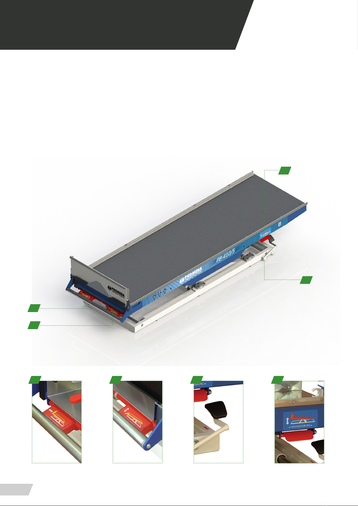
03.1 Commands PB-410
1. Stretcher rear anchor closure
2. Extraction lever
3. Load lever
4. Lateral shift lever
5. Trendelemburg movement lever
03 OPERATION
1
4
2
3
5
12345

USER GUIDE // BENCH PB-410 SERIES
Review 09/19
16
03.1 Commands PB-410/3
1. Stretcher rear anchor closure
2. Extraction lever
3. Load lever
4. Trendelemburg movement lever
5. Lateral shift lever
6. Longitudinal shift lever
1
6
2
3
4
12345
03 OPERATION
5
USER GUIDE // BENCH PB-410 SERIES
Review 09/19
17
03.1 Commands PB-410/4
1. Stretcher rear anchor closure
2. Extraction lever
3. Load lever
4. Lateral shift lever
5. Trendelemburg movement lever
1
4
2
3
5
12345
03 OPERATION
USER GUIDE // BENCH PB-410 SERIES
Review 09/19
18
03.1 Commands PB-410/5
1. Extraction lever
2. Load lever
3. Lateral shift lever
4. Trendelemburg movement lever
3
1
2
4
1 2 3 4
03 OPERATION
USER GUIDE // BENCH PB-410 SERIES
Review 09/19
19
03.2 Manual system elements
LATERAL SHIFT
Operate the lever located on the rear right side of the bench,
exerting a little eort on it with the foot accompanying this
movement with its slide with the hands.
The total lateral displacement is 300 mm.
LONGITUDINAL DISPLACEMENT PB-410/3 MODEL
Operate the lever located on the front right side of the
bench, exerting a little eort on it with the foot accompan-
ying this movement with its slide with the hand.
The total longitudinal displacement is 360 mm.
360
300
03 OPERATION
USER GUIDE // BENCH PB-410 SERIES
Review 09/19
20
03 OPERATION
03.2 Manual system elements
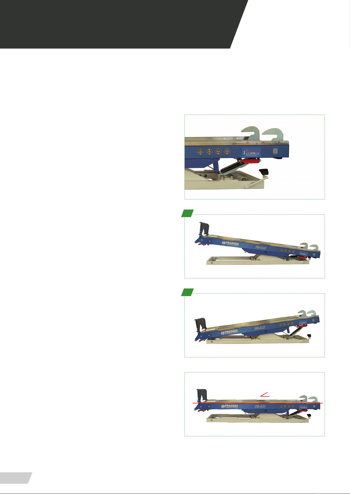
TRENDELEMBURG (Proclive / Declive)
The movement is produced while pressing the side lever,
when released it will lock the position.
· Trendelemburg proclive position(1):
In this position the bench lifts from the position in which the
patient’s head is located.
· Trendelemburg declive position (2):
In this position the bench lifts from the position in which the
patient’s feet are located.
ZERO POSITION OR REST POSITION
Zero position, also known as rest position is that the bench
is completely horizontal and folded upon itself.
1
2
0º
Other manuals for PB-410 Series
1
This manual suits for next models
4
Table of contents
Other Promeba Industrial Equipment manuals


