Promeba PB460/0 User manual

USER GUIDE
Read the instruction
manual and store it for
future reference
ELECTRICAL STRETCHER SUPPORT
SERIES: PB460/0 - PB460/1 - PB460/2
Review 03/20

3
USER GUIDE // ELECTRICAL STRETCHER SUPPORT SERIES: PB460/0 - PB460/1 - PB460/2
Review 03/20
INDEX
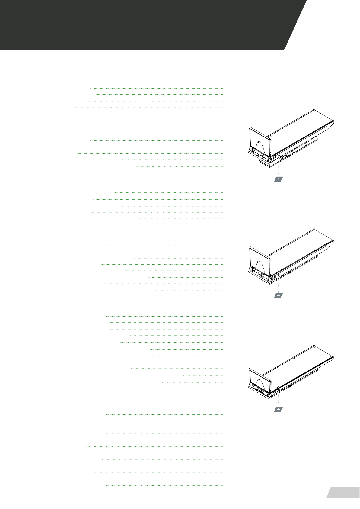
MODEL PB-460/2
MODEL PB-460/1
MODEL PB-460
01 INTRODUCTION
01.1 Using this manual 04
01.2 Meaning of Symbols 05
01.3 Serving request 05
01.4 Demolition 05
01.5 Technical data sheet 06
2 WARNINGS
02.1 General warnings 08
02.2 Specic warnings 11
02.3 Residual risk 13
02.4 Contradictions and side eects 13
02.5 Physical requirements of the operators 13
03 INSTALATION
03.1 Transporting and unpacking 14
03.2 Device’s preparaion 15
03.3 Ambulance compartment check 16
03.4 Anchorage points 18
03.5 Connection to the main power supply 19
04 OPERATING
04.1 Commands 21
04.1.1 Setting up and adjustments 22
04.1.2 Hand control 22
04.1.3 Emergency stop button 22
04.1.4 Loading and unloading operation 23
04.1.5 Side-shift lever 24
04.1.6 Electric motion within the ambulance 25
05 MOUNTING AND COMPONENTS
05.1 Main exploded view PB460 26
05.2 Main exploded view PB461 28
05.3 Main exploded view PB462 30
05.4 Base platform exploded view PB460 32
05.5 Base legs exploded view PB460 34
05.6 Base platform exploded view PB461 & PB462 36
05.7 Base legs exploded view PB461 & PB462 38
05.8 Top platform exploded view PB460 & PB461 40
05.9 Top platform exploded view PB462 42
05.10 High stretcher support PB460 & PB461 ramp exploded view 44
05.11 Low stretcher support PB462 ramp exploded view 46
06 ELECTRICAL CIRCUIT DIAGRAM
06.1 Electric system diagram 49
06.2 Electrical wiring diagram 50
06.3 Hand control operation 51
07 GENERAL MAINTENANCE 53
08 LEGAL NOTICES 54
09 PRODUCT WARRANTY 55
10 TRAINING REGISTER 56
11 MAINTENANCE REGISTER 57

USER GUIDE // ELECTRICAL STRETCHER SUPPORT SERIES: PB460/0 - PB460/1 - PB460/2
Review 03/20
4
01.1 Using this manual
This manual provides using and maintenance instruc-
tions of the product, as well as the way of xing minor
faults that could appear.
It is recommended before the operation of the product
to read carefully this manual in order to avoid damages
caused by a misuse.
Do not lose this document, it should be accessible to
any doubt that could appear by medical personnel.
Remember that a good use and maintenance are ne-
cessary for the proper operation of the product.
Each product incorporates an identication sticker with
the serial number and the model. Keep these numbers
so that they can be indicated to the dealer if necessary.
01 INTRODUCTION

5
USER GUIDE // ELECTRICAL STRETCHER SUPPORT SERIES: PB460/0 - PB460/1 - PB460/2
Review 03/20
01 INTRODUCTION
01.2 Meaning of Symbols
01.3 Serving request
For information of the correct interpretation of the instruction manual, the use, maintenance, insta-
llation and restoration of the product, please contact Promeba customer service T. 93 837 12 00, Fax
Sallent (Barcelona) · SPAIN.
02.4 Demolition
When the devices are no longer suitable for use, if they have not been contaminated by any particular
agent, they can be disposed of as normal solid waste, otherwise, follow the current demolition regula-
tions.
General warning of
possible injuries
Read the user manual
This product is compliant
with the specications of
the Directive 93/42/CEE
Certicate of Qua-
lity Management
System
IQNet Certicate QR Code
(Access Online Web)
WARNINGS FOR THE CORRECT DISPOSAL OF THE PRODUCT IN ACCORDANCE WITH EC DI-
RECTIVE 2012/19/EU WEEE:
At the end of his life, the product must not be disposed as household waste. Can be taken to
special recycling centers provided by local government, or return it to the dealer on purchase
of a new device of the same type and used for the same functions. Dispose of the product
separately avoids possible negative consequences for the environment and human health re-
sulting from inappropriate disposal and allows to recover the materials in order to obtain sig-
nicant savings in energy and resources. The symbol on the label indicates separate collection
of electrical and electronic equipment.
Warning: One incorrect disposal of electrical and electronic equipment could result in sanc-
tions.
ER-0687/1998
This manual suits for next models
2
Other Promeba Industrial Equipment manuals


