ProMeister PT5229 User manual

No. 1 2 3 4 5 6 7 8 9 10
Description Pressure
Plate
Installing
Back-Up
Ring
Removal
Back-Up
Ring
Spindle
Installing
Centering
Bushing
Removal
Centering
Bushing
Screw
M8x35L
Forcing
Bolt
Spindle
Nut
VW T 5
Sleeve
Qty1111112511
Wheel hub installation with the help of a workshop press
Installation of wheel bearing on wheel hub with threaded
spindle (4) and spindle nut (9)
Fig 6
• Before pressing down the bearing with the plunge, please
make sure that all parts are aligned and centered. Then
press down the bearing with regulated pressure on the
wheel hubs with an internal diameter of 68mm.
• First, insert the installation centering bushing (5) with
the diameter 68mm pointing towards the bore hole of
the wheel hub. Then slide the wheel bearing over the
installation centering bushing (5)
• Place and press the bushing sleeve with regulated pressure.
• Place the pressure plate (1) onto the opened vice jaws,
then place the wheel hub on the vice as shown in the
illustration.
• On the wheel hub, an Installing Back-up ring (2) has to be
inserted on the side of the wheel hub as far as it will go.
• Use the box wrench to turn the spindle nut until the wheel
bearing onto the wheel hub.
Fig 7
Fig 8
Wheel
Hub
Bearing
7
8
4
1
2
5
9
1
2
3
4
5
6
7
8
8
9
10
User Guide
Wheel Hub Bearing Puller Set
Produced in Taiwan for
Bileko Car Parts AB
P.O. Box 542
S-645 25 Strängnäs, Sweden
Tel: +46 771 72 00 00
www.promeister.com Art. Nr: PT5229 RVNR-02
Application
Please secure the separate parts properly!
Please lubricate the threaded spindle before each use!
Application
• Please make to carefully read these operating instructions and fully understands all information given before it is
used.
• These user guide contains important information that is necessary for a safe and trouble-free operation of your
Wheel Hub Tool Set.
• For the effectivity of the Wheel Hub Tool Set, as its intended use, it is essential that all the safety and other
information in these operating instructions are adhered to.
• For this reason, always keep his user guide together with your Wheel Hub Tool Set.
• This tool has been designed exclusively for specific applications. We emphasize that any modification to the tool
and/or use on an application not detailed to its intentions are strictly prohibited.
• We are not liable for any injuries to person(s) or damage to property originating from improper application,
misuse of the tool or a disregard of the safety instructions.
• Furthermore, the general safety regulations and the regulations for the prevention of accidents valid for the
application area of this tool must be observed and respected.
• Always keep the tool clean and the user guide together with the tool set at all times.
• All safety equipment must always be within reach and should be checked regularly.
Wheel hub removal with the help of a workshop press
Fig 2
• Remove the wheel bearing and wheel hub out of the spring
strut.
• Insert the 5 forcing bolts (8) into the locating hole of the
pressure plate (1).
• Insert both halves of the removal back-up ring (3) sideways
between the wheel bearing and the wheel hub. Then screw
them together with the 2 cylinder screws (7) M8x35.
• Put the bearing unit onto the forcing bolts (8) in a way that
the forcing bolts (8) pass through the threaded holes of the
wheel hub against the removal back-up ring (3).
• Lay the wheel bearing with the wheel hub and the
installed tools onto the press table with the pressure plate
downwards.
• Insert the removal centering bushing (6) into the wheel
bearing.
• Adjust the wheel bearing with the tools installed so that the
press head’s pressure is applied right onto the center of the
removal centering bushing (6).
• Operate the workshop press until the wheel hub is
separated from the bearing.
• After removing the wheel hub, remove the attached parts.
Please secure the separate parts properly!
Please lubricate the threaded spindle before each use!
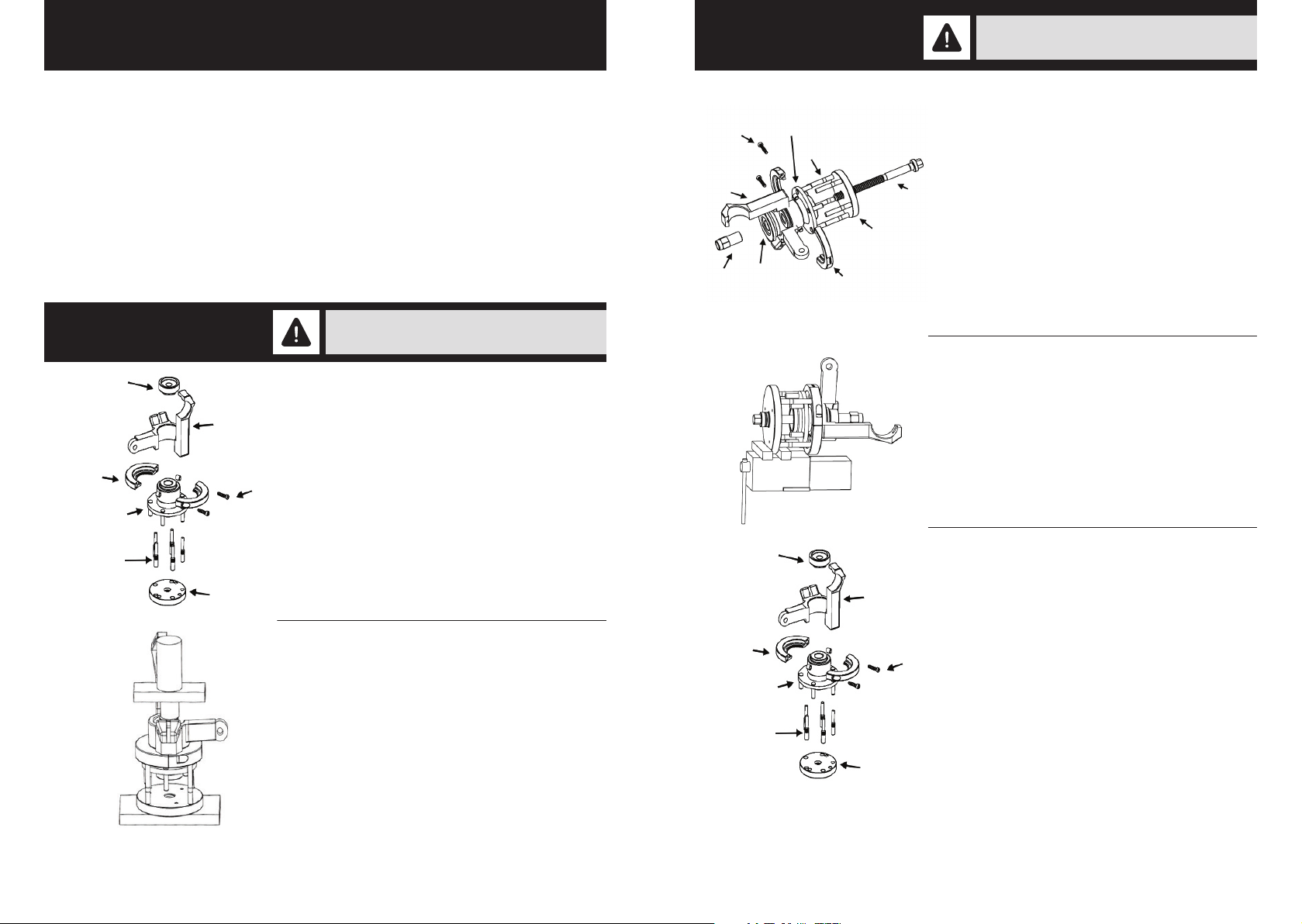
Wheel hub removal with the help of spindle (4) and
spindle nut (9)
Wheel hub removal with the help of spindle (4) and
spindle nut (9) with clamp
Wheel hub installation with the help of a workshop press
Fig 4
• Remove the wheel bearing with the wheel hub out of the
spring strut.
• Insert both halves of the removal back-up ring (3) sideways
between the wheel bearing and the wheel hub and screw
them together with the 2 cylinder screws (7) M8x35.
• Put the threaded spindle (4) and the pressure plate (1)
with 5 forcing bolts (8) inserted onto the wheel bearing/
wheel hub in a way that the forcing bolts (8) pass through
the threaded holes of the wheel hub, against the removal
back-up ring (3).
• Slide the removal centering bushing (6) over the spindle up
to the wheel bearing’s front end.
• Screw the spindle nut (9) onto the spindle.
• Clamp the wheel bearing unit with the wheel hub and the
connected tools into a Machinist’s vice.
• Once the required connection has been reached, it is
necessary to retain the spindle nut (9) with a screw driving
tool (e.g. box wrench) until the wheel hub is separated
from the bearing.
• After the wheel hub removal, then remove the attached
parts.
• Lay the pressure plate (1) onto the press table.
• Place the wheel hub onto the Pressure plate (1) as shown in
the illustration. With an internal diameter of 94mm on the
wheel hub which the installation back-up ring (2) has to be
inserted on the side of the bearing as far as it will go.
• Place both parts with the bore hole downwards onto the
wheel hub. The installation centering bushing (5) centers in
the bore hole of the wheel hub.
• Afterwards, slip the pressure sleeve top-down over the
installation centering bushing (5).
Fig 1 6
3
8
1
7
Wheel
Hub
Bearing
Fig 3
7
8
963
1
4
Bearing
Wheel
Hub
Fig 5 5
2
8
1
7
Wheel
Hub
Bearing
Safety Precaution Application
Please secure the separate parts properly!
Please lubricate the threaded spindle before each use!
Other ProMeister Tools manuals


