promesstec CFS 100 User manual
promesstec GmbH I Niedersachsenstraße 4 I D- 48465 Schüttorf I Tel.:+49 (0)5923/ 90 229 0 I Fax:+49 (0)5923/ 90 229 29
E-Mail: office@promesstec.com I Internet: www.promesstec.com
User manual
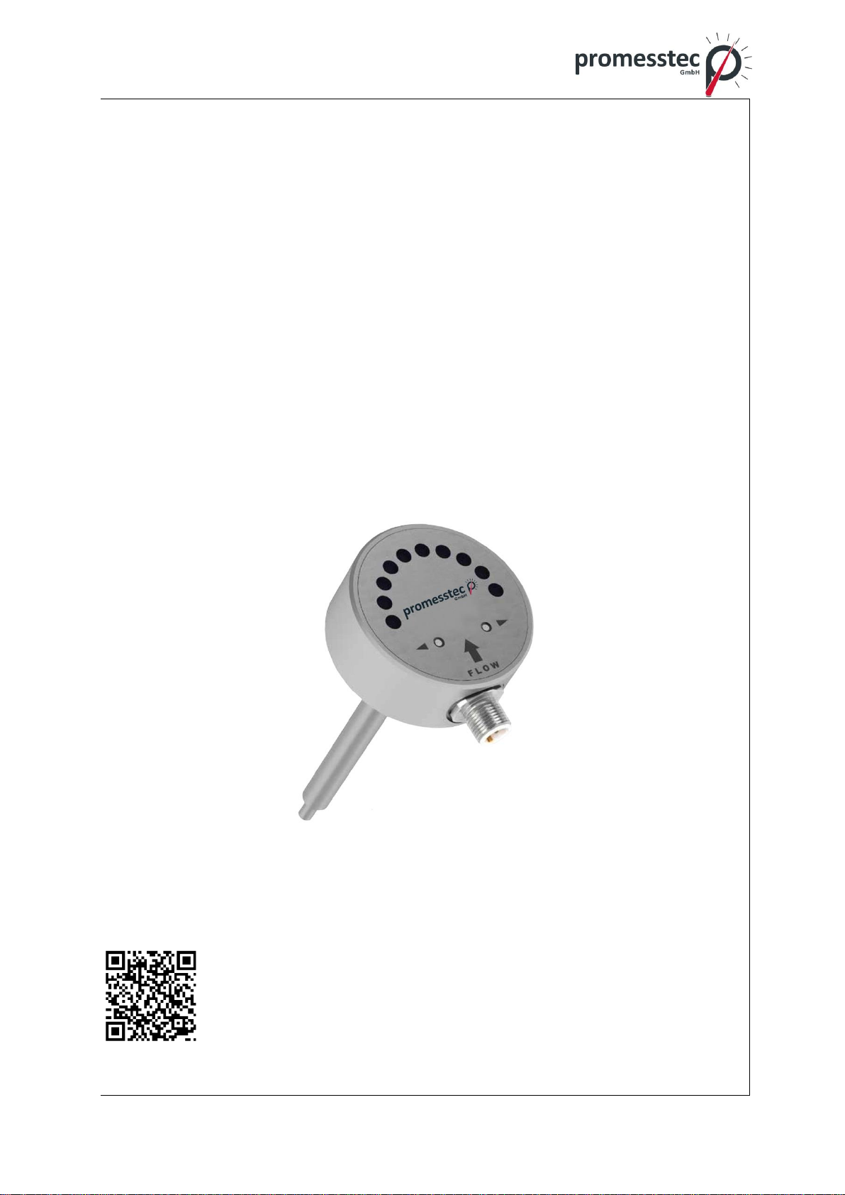
Flow sensor CFS 100
version 2.1.2

2
promesstec GmbH I Niedersachsenstraße 4 I D- 48465 Schüttorf I Tel.:+49 (0)5923/ 90 229 0 I Fax:+49 (0)5923/ 90 229 29
E-Mail: office@promesstec.com I Internet: www.promesstec.com
Content
1. General................................................................................................................ 3
1.1 Description .....................................................................................................3
1.2 Symbols and abbreviations ............................................................................3
2. Transport, packaging and storage...................................................................... 4
2.1 Transport........................................................................................................4
2.2 Packaging.......................................................................................................4
2.3 Storage...........................................................................................................4
3. Safety instructions............................................................................................... 4
3.1 Intended use of the product............................................................................4
3.2 Personnel qualification ...................................................................................5
3.3Special hazards..............................................................................................5
4. Starting, operation............................................................................................... 6
4.1 Process connection........................................................................................6
4.2 Outdoor-Bedingungen....................................................................................6
4.3 Interference sources.......................................................................................6
4.4 Vibration.........................................................................................................7
4.5 Correct installation position ............................................................................7
4.6 Installation ......................................................................................................8
4.7 Electrical installation.......................................................................................8
4.7.1 Electrical connection................................................................................8
4.7.2 NO/NC contact.........................................................................................9
4.8 Starting up....................................................................................................10
5. Adaptation and control....................................................................................... 12
6. Technical data................................................................................................... 13
7. Dimensions........................................................................................................ 14
7.1 Accessories..................................................................................................14
8. Dismounting, Return, Cleaning, Disposal......................................................... 15
8.1 Dismounting .................................................................................................15
8.2 Return...........................................................................................................15
8.3 Cleaning.......................................................................................................15
8.4 Disposal........................................................................................................15
3
promesstec GmbH I Niedersachsenstraße 4 I D- 48465 Schüttorf I Tel.:+49 (0)5923/ 90 229 0 I Fax:+49 (0)5923/ 90 229 29
E-Mail: office@promesstec.com I Internet: www.promesstec.com
1. General
1.1 Description
The flow meter CFS 100 is designed for liquids and is based on the calorimetric
measuring principle, according to which the flow rate of the measured liquid is
proportional to the function of heat transfer from the sensor to the surroundings.
Prompt and simple installation and lower costs thanks to its simple construction
are the principal advantages.
The sensors are not restricted by the electrical conductivity of the liquid. Owing to
the calorimetric measuring principle used, the measurement is dependent on
thermal conductivity of the liquid. The meter can reach its highest sensitivity within
the range of 4 ÷ 150 cm/s for use with water. For other liquids with different ther-
mal conductivity, the measuring range is different. The measuring range can be
modified by user to a certain extent, whereas it holds true that the lower thermal
conductivity of medium, the higher flow rates can be measured.
1.2 Symbols and abbreviations
Warning!
A non-observance can cause injuries to persons and/or the demoli-
tion of the device. There can be a dangerous to life.
Attention!
A non-observance can cause a faulty operation of the device or lead
to property damage.
Info!
A non-observance can have influence on the operation of the device
or cause unintentional reactions of the device.
Danger!
Should the safety instructions not be observed, there is a risk of se-
rious or fatal injury caused by electrical power.
Warning!
Possibly a dangerous situation can occur, which results in burns
because of hot surfaces or liquids, if not avoided.
Flow sensor CFS 100

4
promesstec GmbH I Niedersachsenstraße 4 I D- 48465 Schüttorf I Tel.:+49 (0)5923/ 90 229 0 I Fax:+49 (0)5923/ 90 229 29
E-Mail: office@promesstec.com I Internet: www.promesstec.com
2. Transport, packaging and storage
2.1 Transport
Check the instrument for any damage that may have been caused during transpor-
tation. If, report them immediately. The temperature during transportation and
storage of the meter must be within the range of -10 °C up to 80°C.
2.2 Packaging
Do not remove packaging until just before mounting. Keep the packaging as it will
provide optimum protection during transport (e.g. change in installation site, send-
ing back).
2.3 Storage
For longer term storage avoid the following influences:
1. Direct sunlight or proximity to hot objects
2. Mechanical vibration, mechanical shock (putting it hard down)
3. Soot, vapor, dust and corrosive gases
If possible store the device in original package or an equivalent one.
The temperature during transportation and storage of the meter must be within the
range of -10 °C up to 80°C.
3. Safety instructions
More important safety instructions can be found in the individual
chapters.
3.1 Intended use of the product
The sensor has been designed and built solely for the intended use described
here and may only be used accordingly. The technical specifications contained in
these operating instructions must be observed. Improper handling or operation
of the instrument outside of technical specifications requires the instrument to be
taken out of service immediately and an inspection by the manufacturer. When the
instrument is transported from a cold into a warm environment, the formation of
condensation may result in the instrument malfunctioning. Before putting it back
into operation, wait for the instrument temperature and the room temperature to
5
promesstec GmbH I Niedersachsenstraße 4 I D- 48465 Schüttorf I Tel.:+49 (0)5923/ 90 229 0 I Fax:+49 (0)5923/ 90 229 29
E-Mail: office@promesstec.com I Internet: www.promesstec.com
equalize. The manufacturer shall not be liable for claims of any type based on op-
eration contrary to the intended use.
3.2 Personnel qualification
Improper handling can result in considerable injury and damage to
equipment.
- The activities described in these operating instructions may only
be carried out by skilled personnel who have the qualifications de-
scribed below.
- Keep unqualified personnel away from hazardous areas.
For installation and starting of the temperature sensor the personnel has to be fa-
milar with the relevant regulations and directives of the country and must have the
qualification required. They must have knowledge on measurement and control
technology, have to be acquainted with electric circuits, are capable of carrying out
the work described and can independently recognize potential hazards. Depend-
ing on the operation conditions of the application they have to have the corre-
sponding knowledge, e.g. of aggressive media.
3.3 Special hazards
For hazardous media such as oxygen, acetylene, flammable or tox-
ic gases or liquids, refrigeration plants, compressors, etc., in addi-
tion to all standard regulations, the appropriate existing codes or
regulations must also be followed.
If you do not observe the appropriate regulation, serious inju-
ries and/or damage can occur!
A protection from electrostatic discharge (ESD) is required. The
proper use of grounded work surfaces and personal wrist straps is
required when working with exposed circuitry (PCB, printed circuit
boards), in order to prevent static discharge from damaging sensi-
tive electronic components.
There is a danger of death caused by electric current. Upon contact
with life parts, there is a direct danger of death. Electrical instru-
ments may only be installed and connected by skilled electrical per-
sonnel. Operation using a defective power supply unit (e.g. short
circuit from the mains voltage to the voltage output) can result in
life-threatening voltages at the instrument.

6
promesstec GmbH I Niedersachsenstraße 4 I D- 48465 Schüttorf I Tel.:+49 (0)5923/ 90 229 0 I Fax:+49 (0)5923/ 90 229 29
E-Mail: office@promesstec.com I Internet: www.promesstec.com
Residual media in dismounted instruments can result in a risk to
personnel, the environment and equipment. Take sufficient precau-
tionary measures. Do not use this instrument in safety or Emergen-
cy Stop devices. Incorrect use of the instrument can result in injury.
Should a failure occur, aggressive media with extremely high tem-
perature and under high pressure or vacuum may be present at the
instrument.
4. Starting, operation
4.1 Process connection
The flow meter monitor is usually delivered with a stainless steel sleeve nut
M16x1.5 and with installed stainless steel cutting ring in the position that allows
maximum insertion of the sensor into piping. After installation of the stainless steel
cutting ring onto the sensor, it is not possible to change the depth of insertion of
the sensor into piping; it is only possible when the PTFE ring is used special order
necessary.
The accessories to the flow sensor may include various necks (adapters) serving
for process installation and M12 (4-pin) connectors for electrical connection.
4.2 Outdoor conditions
It is necessary to prevent the flow sensor from being directly exposed to weather
conditions and prevent the liquid to be measured from freezing over inside the flow
sensor, which might damage the measuring tube.
In the case that the unit is located outdoors, promesstec recommends a protective
case, and if appropriate, a roof to avoid direct sunshine so that the evaluation elec-
tronics cannot warm up excessively.
4.3 Interference sources
The most frequent interference sources affecting the stable flow of liquid are as
follows:
-Pumps and bends or elbows located closely one after another in various
planes. These elements should be found at least at a distance of 20xd
(where d is the inside diameter of the meter in millimeters) before the flow
sensor.
-The flow of liquid in the flow detector should be settled and free of whirls.
Minimal recommended distances are 5xd before and 3xd after sensor.
-Abrupt variations of pipe cross-section if not made as a cone with an angle
of α≤10° (where αis the angle made by beveled walls of the pipe adapter).
-Whatever interfering in the flow of liquid, e.g. thermometer well.
7
promesstec GmbH I Niedersachsenstraße 4 I D- 48465 Schüttorf I Tel.:+49 (0)5923/ 90 229 0 I Fax:+49 (0)5923/ 90 229 29
E-Mail: office@promesstec.com I Internet: www.promesstec.com
-When a mixture of substances is made ( or mixture of the same liquids with
different temperatures) you need to install the flow meter either before the
mixing location or at a sufficient distance after it (min.30xd), otherwise the
indication may be unstable
-Branch lines, T-pieces, bends, elbows, slide valves, taps, flaps. Shut-off
valves, control valves, butterfly valves and non-return valves. Pipe outputs
from reservoirs, exchangers and filters.
4.4 Vibration
The scope and level of vibrations must be below 2.2 g in the range of 20 ÷ 50Hz
frequencies according to IEC 068-2-34 standard.
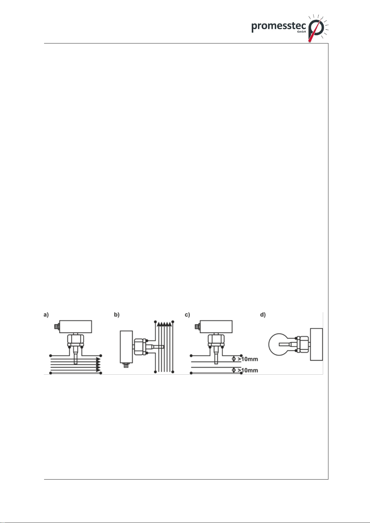
4.5 Correct installation position
The flow detector (sensor), particularly its tip must be fully immersed (see Fig. a).
For this reason, we do not recommend installing in the highest point of piping that
may become aerated, or in sloping or even in horizontal piping with the open end
into which air may penetrate, but conversely, in rising piping (see Fig. b).
Furthermore, the distance of the sensor tip from piping should be more than 11mm
(see Fig. c).
During long-lasting measurements of very low flow rates (Q < 0.1 m/s), impurities
may be deposited. In this case, carry out installation at horizontal piping sideways
(see Fig. d).
8
promesstec GmbH I Niedersachsenstraße 4 I D- 48465 Schüttorf I Tel.:+49 (0)5923/ 90 229 0 I Fax:+49 (0)5923/ 90 229 29
E-Mail: office@promesstec.com I Internet: www.promesstec.com
4.6 Installation
Before mounting is started, make sure that the system is depressurized or dis-
charged. After that, install a suitable adapter to a T-piece or in some case in a
welded-on piece or right on the pipe wall with adequate thread sealing. Then in-
stall the flow monitor in the adapter. In case of the stainless steel cutting ring, the
length of insertion of the sensor in the adapter is given by the assembly of the
built-in ring and cannot be changed. The length of insertion of the sensor can only
be changed when using a ring made of PTFE. Tighten the stainless steel ring
sleeve nut with the torque of 70Nm max. (in case of PTFE ring, 50Nm max).
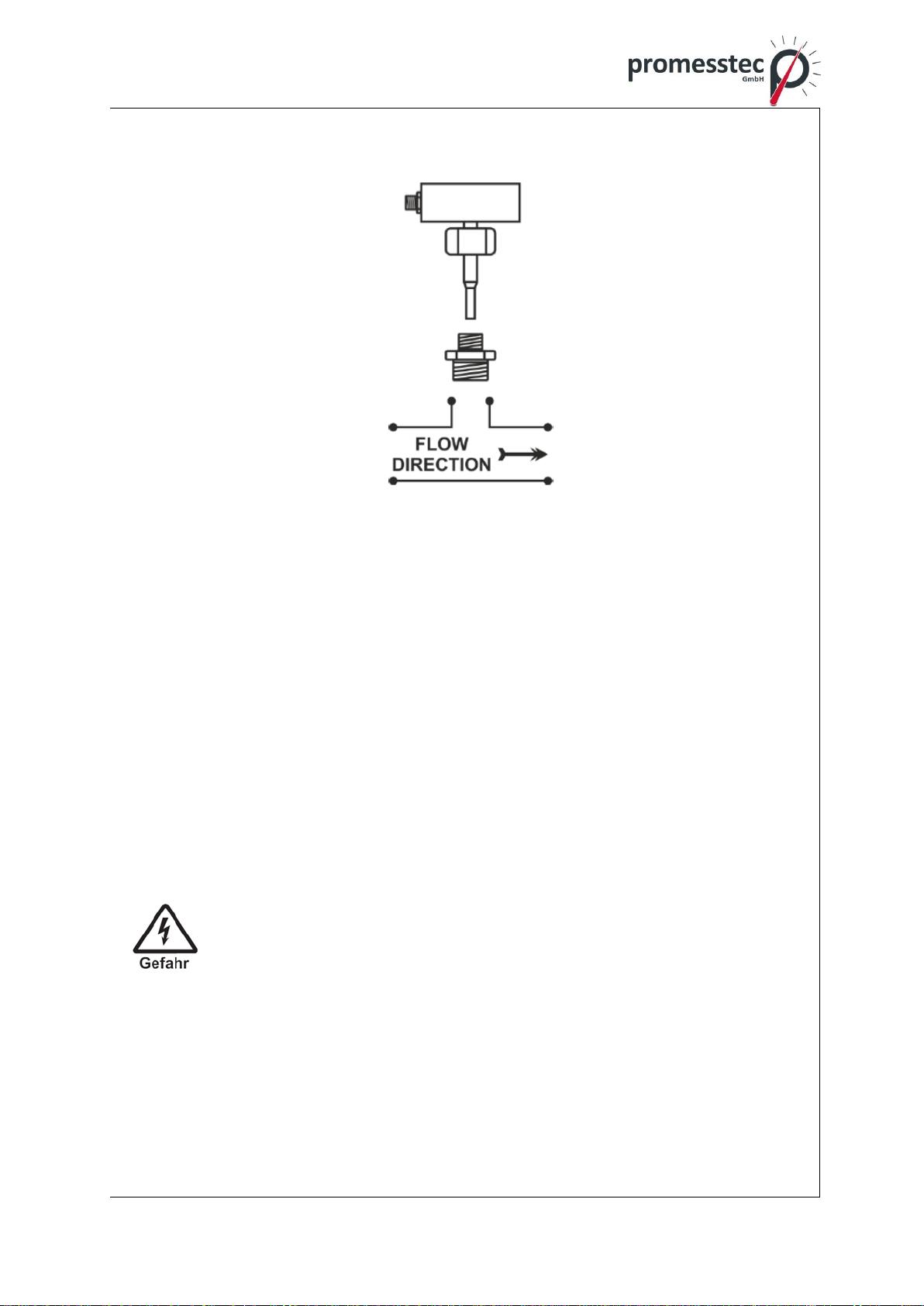
When installed in piping and for the most precise flow evaluation, adhere to the
orientation of the unit so that the M12 connector for electrical connection can form
an upstream edge. So the medium should run from the same side where this con-
nector is found.
4.7 Electrical installation
Always carry out any handling operations or installation of the de-
vice after disconnection of the supply voltage!!!
When the below mentioned operations are carried out unprofes-
sionally, the claim to warranty become null and void!!!
4.7.1 Electrical connection
M12 connector wiring (compact version):
9
promesstec GmbH I Niedersachsenstraße 4 I D- 48465 Schüttorf I Tel.:+49 (0)5923/ 90 229 0 I Fax:+49 (0)5923/ 90 229 29
E-Mail: office@promesstec.com I Internet: www.promesstec.com
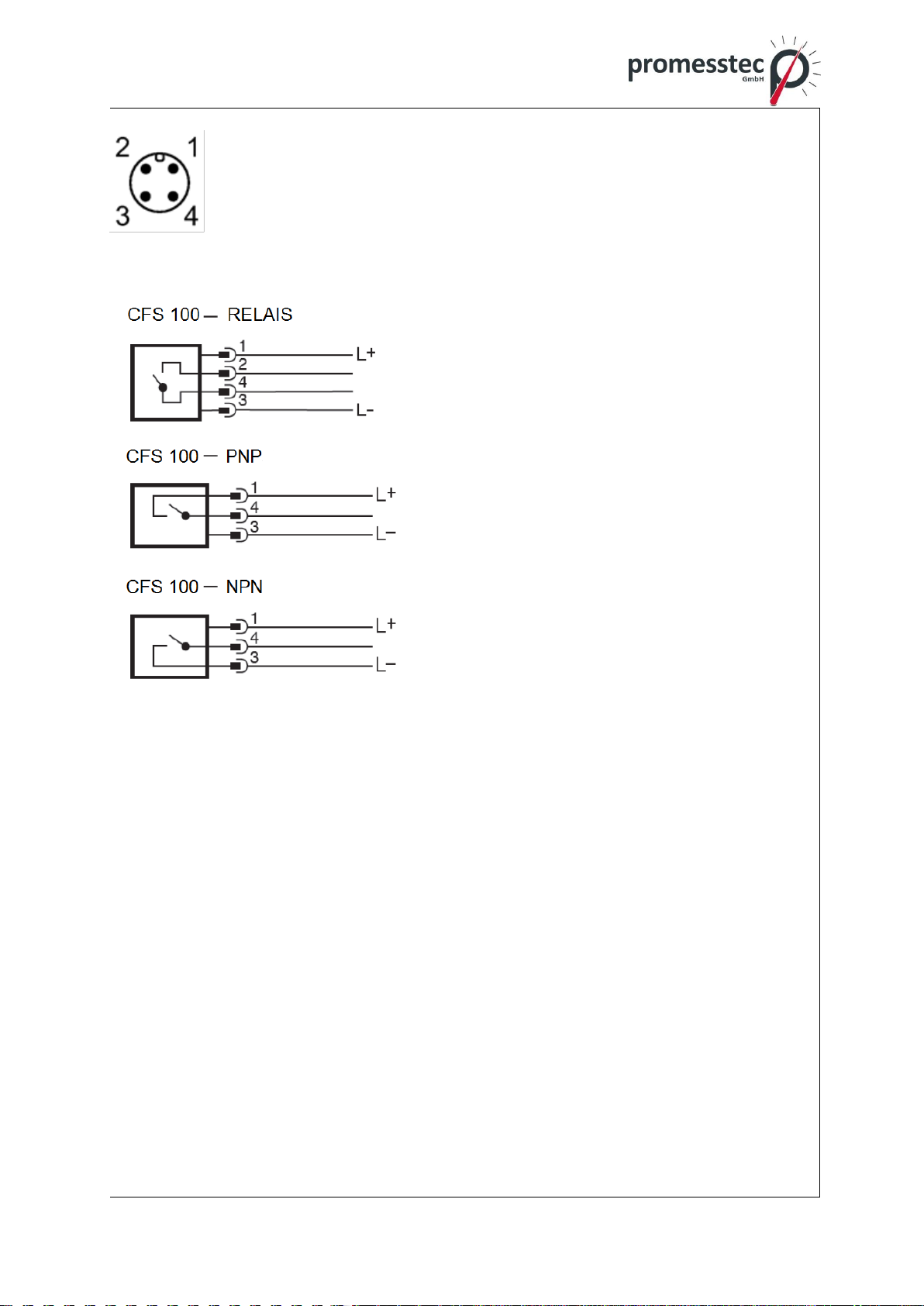
The flow monitor is equipped with a standard M12x1 connector with
4 pins.
The pin connection corresponds to the type of outputs and is shown
on the tag plate of sensor.
Standard switch contact connection:
PIN 1 –supply voltage +24V
PIN 2 –relay contact switch point
PIN 3 –supply voltage GND
PIN 4 –relay contact switch point
PIN 1 –supply voltage +24V
PIN 4 –supply voltage GND
PIN 3 –PNP contact switch point
PIN 1 - supply voltage +24V
PIN 4 - supply voltage GND
PIN 3 –NPN contact switch point
4.7.2 NO/NC contact
The manufacturer delivers the meter with the switching point set as a contact
maker unit. If the flow rate on compact version is above switching point, relay con-
tact on pin 2 and pin 4 is closed (eventually is closed PNP/NPN contact on pin 4).
If the flow rate is below switching point, relay contact is open.
In case of separate version for DIN rail and with relay output when the flow is
above switching point are pin 5 and 6 closed (eventually is closed PNP/NPN con-
tact on pin 5 according to the wiring)
The function of contact maker/breaker can be changed by user to inverted logic if
needed.
The typical response time is 1 ÷ 6sec and it is influenced by the rate of change of
flow:
-The change of flow moves close to the switching point –slower response.
-The change of flow jumps over the switching point –quick response.

10
promesstec GmbH I Niedersachsenstraße 4 I D- 48465 Schüttorf I Tel.:+49 (0)5923/ 90 229 0 I Fax:+49 (0)5923/ 90 229 29
E-Mail: office@promesstec.com I Internet: www.promesstec.com
The designation of a switching point on the LED scale can be implemented in two
colors that indicate simultaneously if the switching contact is closed or open:
- Red LED –open contact
- Amber LED –closed contact
4.8 Starting up
After powering the flow switch make a self-test and self-diagnostics LED, then
goes fluently to the measuring mode.
Compact version:
first LED flashing = the last LED flashing = the the flow velocity is within
flow is below the monitor flow is above the the adjusted monitoring
monitoring range monitoring range range

11
promesstec GmbH I Niedersachsenstraße 4 I D- 48465 Schüttorf I Tel.:+49 (0)5923/ 90 229 0 I Fax:+49 (0)5923/ 90 229 29
E-Mail: office@promesstec.com I Internet: www.promesstec.com
The number of green illuminated LEDs roughly indicates the flow rate within the
given range.
If none of the LEDs is lit or flashing, the device is most likely dis-
connected from the supply voltage!!!
Basic parameter default setting
The flow monitor parameters are set by the manufacturer according to purchase
order. The device is set to default parameters by the manufacturer (see the Table
below). The operator may make alterations by means of two buttons on the panel
of the device (S. 13).
Factory settings for water:
Minimum flow rate
<8cm/s (2% Qmax)
First LED flashing
Switching point
40cm/s (10% Qmax)
Red/amber LED
Maximum flow speed
>400cm/s (100%
Qmax)
Last LED flashing
Note: The value of switching point in the table are only informative and depend on
the fact if the flow rate increase or decrease with time, i.e. this switching point
have a hysteresis, which is set by the manufacturer.
Tableview of LEDs according to the percentage of settings of maximal flow.
(Factory setting of speed is standardly Qmax = 4m/s)
LED-display
Flow velocity in % of setting setting
Qmax
Flashing LED 1
below 2%
Lighting LED 1
2-5%
Lighting LED 2
5-10%
Lighting LED 3
10-15%
Lighting LED 4
15-20%
Lighting LED 5
20-25%
Lighting LED 6
25-35%
Lighting LED 7
35-47,5%

12
promesstec GmbH I Niedersachsenstraße 4 I D- 48465 Schüttorf I Tel.:+49 (0)5923/ 90 229 0 I Fax:+49 (0)5923/ 90 229 29
E-Mail: office@promesstec.com I Internet: www.promesstec.com
Lighting LED 8
47,5-62,5%
Lighting LED 9
62,5-80%
Lighting LED 10
80-100%
Flashing LED 10
above 100%
5. Adaptation and control
Switching point
Press down the button and hold until the green LEDs start flashing. After the
button is released, the red LED indicating switching/circuit-opening point starts
flashing. Using the buttons you can move this switching point to the positions
of LED 2 to 9. After completion of the setting, wait until automatic storage
operation is over and the meter goes to measuring mode.
The change in logic of NC/NO output
Press down simultaneously the buttons on the meter panel and hold unless
green LEDs start flashing. After the buttons are released, the change of NC/NO
contact is activated.
MINIMUM flow calibration in the monitor
In order to calibrate the MINIMUM flow, press down the button and hold it until
the red LEDs start flashing. After releasing the button, the MINIMUM flow will be
automatically registered and the sensor returns to measurement mode. MINIMUM
calibration is completed by this action. Carry out this setting only if necessary
(usually, after using with an oil medium, etc.), this default factory setting done for
water.
MAXIMUM flow calibration in the monitor
In order to calibrate the MAXIMUM flow, press down the button and hold it until
the red LEDs start flashing. After releasing the button, the MAXIMUM flow will be
automatically registered and the sensor returns to measurement mode. MAXIMUM
calibration is completed by this action. Carry out this setting only if necessary
(usually, after using with an oil medium, etc.), this default factory setting done for
water.
Restoring parameters to factory default values
Press down simultaneously the buttons on the meter panel and hold them
until red LEDs start flashing (red REDs flashing precedes green LEDs flashing,
serving for changing the polarity of NC/NO contact). After releasing both buttons,
RESET is applied and factory defaults are restored.

13
promesstec GmbH I Niedersachsenstraße 4 I D- 48465 Schüttorf I Tel.:+49 (0)5923/ 90 229 0 I Fax:+49 (0)5923/ 90 229 29
E-Mail: office@promesstec.com I Internet: www.promesstec.com
6. Technical data
Supply voltage 24V ±10% DC with polarity reversal protec-
tion
Input power 1.5/4VA
Electrical connection connector M12 x 1-4 pin
Process connection see accessories
Sensor version compact
Indicator 10x tri-colour LED (flow velocity)
Contact rating 130mA/ 60V/ 500mW
Status contact SSR, passive, potential free, max 350V
AC/DC, 150mA, 400 m W
Response time 1 ÷ 6sec for water (25°C)
Flow ranges 4 ÷ 400cm/s
Accuracy ± 2 ÷ ± 8cm/s
Hysteresis 2 ÷ 8cm/s
Control 2× flush-mounted button
Temperature of liquid -10 ÷ +80°C
Ambient temperature -20 ÷ +55°C
Material in contact with medium stainless steel 1.4404, PTFE
(according to the connection option)
Maximum pressure 100 bar
IP code IP67
Ambient humidity max. 90%
Dimensions (H x W x D):
- compact: 91x74x60mm (in case of the longer version,
the height is 151mm)
Weight 290g
14
promesstec GmbH I Niedersachsenstraße 4 I D- 48465 Schüttorf I Tel.:+49 (0)5923/ 90 229 0 I Fax:+49 (0)5923/ 90 229 29
E-Mail: office@promesstec.com I Internet: www.promesstec.com
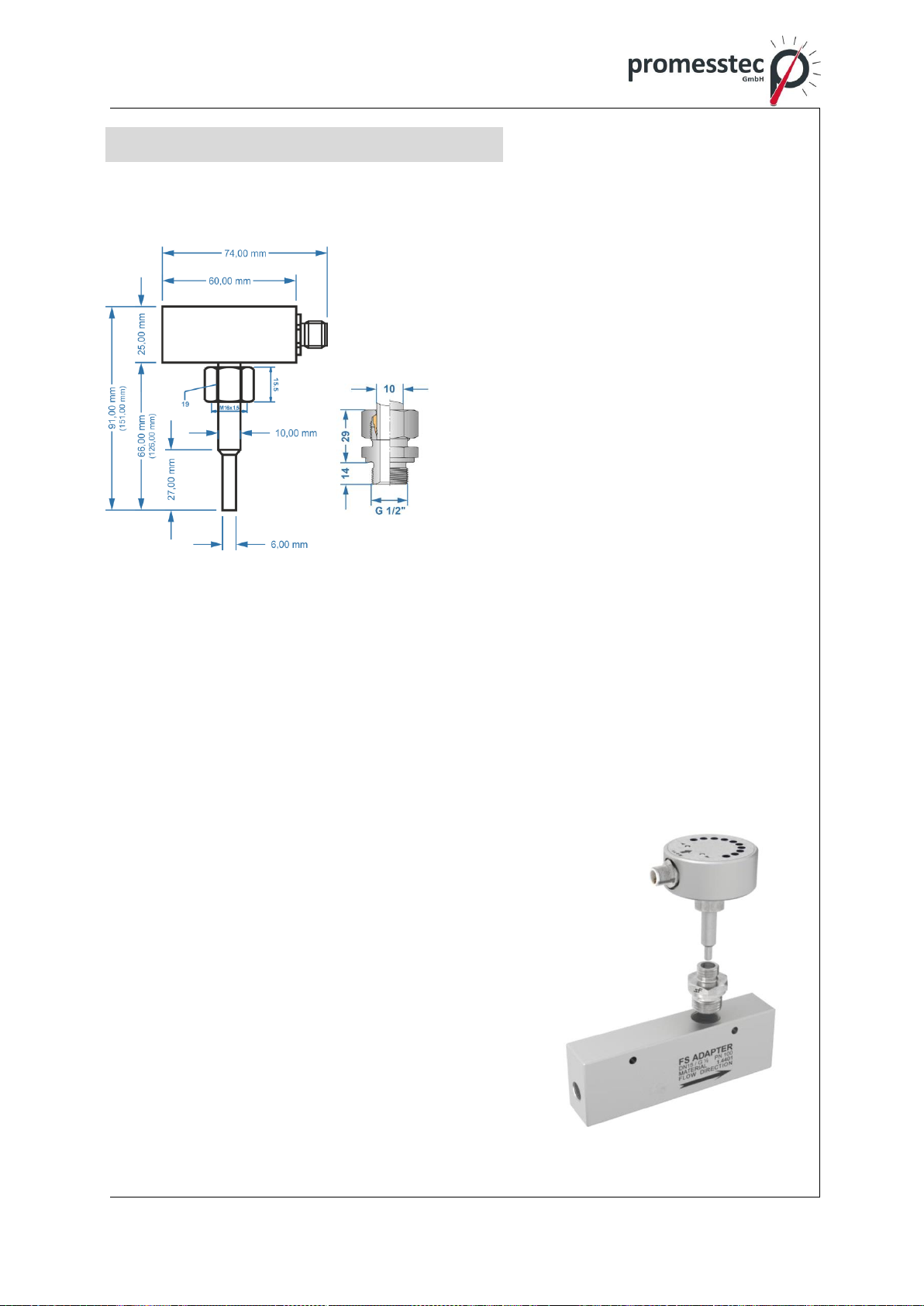
7. Dimensions
Compact version
7.1 Accessories
In case when it is necessary to monitor the media flow in pipe with a smaller DN
than DN 25 (or the flow velocity is below the sensor range at the pipe diameter
given), it is possible to use an adapter block with a corresponding flow velocity and
ensure correct operation and keep the installation conditions in this way.
Adapters are designed for short version of sensor 65mm with using direct socket
with pipe thread G ½’’.
Individual designs:
FS adapter block DN20/G3/4“ 1 ÷ 10 l/Min. (di-
mensions 150×50×40 mm)
FS adapter block DN15/G1/2“ 0,5 ÷ 5 l/Min. (di-
mensions 150×50×30 mm)
FS adapter block DN10/G1/4“ 0,2 ÷ 2 l/Min. (di-
mensions 150×50×30 mm)
FS adapter block DN4,7/G1/4“ 50 ÷ 500 ml/Min.
(dimensions 70×50×30 mm)
FS adapter block DN2,7/G1/4“ 2 ÷ 100 ml/Min.
(dimensions 70×50×30 mm)
15
promesstec GmbH I Niedersachsenstraße 4 I D- 48465 Schüttorf I Tel.:+49 (0)5923/ 90 229 0 I Fax:+49 (0)5923/ 90 229 29
E-Mail: office@promesstec.com I Internet: www.promesstec.com
8. Dismounting, Return, Cleaning, Disposal
8.1 Dismounting
Residual media in dismounted instruments can result in a risk of
personnel, the environment and equipment. Take sufficient pre-
cautionary measures.
There is a risk of burns. Let the instrument cool down sufficiently
before dismounting. During dismounting there is a risk of danger-
ously hot pressure media escaping.
Only disconnect the resistance thermometer once the system has
been depressurized.
8.2 Return
When returning the instrument, use the original packaging or a
suitable package. To avoid damage, use for example antistatic
plastic film, shock-absorbent material, a marking as highly sensi-
tive measuring instrument.
8.3 Cleaning
Before cleaning the instrument disconnect the electrical connec-
tion.
Clean the instrument with a moist cloth.
Electrical connections must not come into contact with moisture.
Wash or clean the dismounted instrument before returning it in or-
der to protect personnel and the environment from exposure to re-
sidual media.
Residual media in dismounted instruments can result in a risk to
persons, the environment and equipment. Take sufficient precau-
tionary measures.
8.4 Disposal
Dispose instrument components and packaging materials in ac-
cordance with the respective waste treatment and disposal regula-
tions of the region or country to which the sensor is supplied.
Table of contents


 Specifications")


