promesstec PPR 500 User manual

promesstec GmbH I Niedersachsenstraße 4 I D- 48465 Schüttorf I Tel.:+49 (0)5923/ 90 229 0 I Fax:+49 (0)5923/ 90 229 29
E-Mail: office@promesstec.com I Internet: www.promesstec.com
User Manual
Paperless Recorder/Datalogger
PPR 500
Version 2.1.1

2
promesstec GmbH I Niedersachsenstraße 4 I D- 48465 Schüttorf I Tel.:+49 (0)5923/ 90 229 0 I Fax:+49 (0)5923/ 90 229 29
E-Mail: office@promesstec.com I Internet: www.promesstec.com
Inhalt
................................................................................................................................... 5
1. Safety Symbols ................................................................................................... 5
2. Safety Notes and Precautions............................................................................. 5
3. Static Electricity................................................................................................... 6
4. General Description............................................................................................. 7
4.1 Unique features of recorder............................................................................ 7
4.2 Comparison of PPR series Recorders.......................................................... 10
4.3 Expandable Input and Output cards ............................................................. 11
4.4 Communication............................................................................................. 14
4.5 External Storage media ................................................................................ 14
4.6 Smart Mechanism......................................................................................... 15
4.7 Ordering code and accessories.................................................................... 16
4.7.1 Ordering code PPR 500.........................................................................16
4.7.2 Accessories:...........................................................................................18
4.8 Specifications................................................................................................ 18
5. Installation and wiring........................................................................................ 22
5.1 Unpacking..................................................................................................... 22
5.2 Installation .................................................................................................... 23
5.3 Panel mounting style .................................................................................... 23
5.4 Setup input and output.................................................................................. 26
5.5 Wiring of the cards........................................................................................ 31
5.6 RS-232, RS-422, RS-485 wiring................................................................... 38
5.7 External Memory Card:................................................................................. 39
6. Basic functions of recorders.............................................................................. 40
6.1Configuration ................................................................................................ 40
6.2 Standard and Plus Version of Firmware ....................................................... 41
6.3 Communication with Third Party Interfaces .................................................. 42
6.4 Information Accessibility through WEB......................................................... 42
6.5 Handwriting Messages on Trend Screens.................................................... 43
6.6 Custom Editted Display Screens .................................................................. 47
6.7 Analog Input Log Speed Flexibility................................................................ 48
6.8 High Speed Input.......................................................................................... 48
6.9 System Clock Synchronization via Internet................................................... 48
6.10 Increased Security in Password configuration........................................... 48

3
promesstec GmbH I Niedersachsenstraße 4 I D- 48465 Schüttorf I Tel.:+49 (0)5923/ 90 229 0 I Fax:+49 (0)5923/ 90 229 29
E-Mail: office@promesstec.com I Internet: www.promesstec.com
6.11 Auto Output to Printer................................................................................ 48
6.12 External Channels ..................................................................................... 48
6.13 Batch ......................................................................................................... 48
6.14 FDA 21 CFR PART 11............................................................................... 48
7. Configuration..................................................................................................... 49
7.1 Channel........................................................................................................ 50
7.1.1 Analog Input...........................................................................................50
7.1.2 Digital Input............................................................................................57
7.1.3 Math Channel.........................................................................................59
7.1.4 Analog Output........................................................................................71
7.1.5 Digital Output.........................................................................................71
7.1.6 External..................................................................................................72
7.1.7 Jobs.......................................................................................................73
7.2 Display.......................................................................................................... 76
7.2.1 Status Bar..............................................................................................77
7.3 Timer ............................................................................................................ 78
7.4 Clock............................................................................................................. 81
7.5 Communication............................................................................................. 82
7.5.1 Connections...........................................................................................84
7.5.2 Commands.............................................................................................85
7.5.3 Modbus RTU Master, Example1............................................................86
7.5.4 Modbus RTU Master, Example2............................................................88
7.5.5 Modbus RTU Slave , Example...............................................................90
7.6 Instrument..................................................................................................... 91
7.7 Security......................................................................................................... 92
7.7.1 Normal ...................................................................................................92
7.7.2 CFR-21 ..................................................................................................93
7.8 Demo............................................................................................................ 94
7.9 Auto-Output .................................................................................................. 94
7.9.1 USB Printer............................................................................................95
7.9.2 Network Printer (LPT1) ..........................................................................97
7.9.3 Print Historical data................................................................................99
7.9.4 Print Reports........................................................................................100
7.9.5 Print Snapshot .....................................................................................101
7.10 System Info.............................................................................................. 102
7.11 Batch Control........................................................................................... 104

4
promesstec GmbH I Niedersachsenstraße 4 I D- 48465 Schüttorf I Tel.:+49 (0)5923/ 90 229 0 I Fax:+49 (0)5923/ 90 229 29
E-Mail: office@promesstec.com I Internet: www.promesstec.com
7.12 Calibrate .................................................................................................. 112
8. PC based software.......................................................................................... 115
8.1 Free Basic Software ................................................................................... 115
8.1.1 Requirements.......................................................................................115
8.1.2 Operating system.................................................................................116
8.1.3 Software...............................................................................................116
8.1.4 Ethernet Configuration.........................................................................119
8.2 Data Acquisition Studio Software................................................................ 122
8.2.1 Requirements.......................................................................................122
8.2.2 Operating system.................................................................................122
8.2.3 Software...............................................................................................122
8.2.4 How to configure Communication Bank...............................................123
8.2.5 How to configure Recorder ..................................................................125
8.2.6 Touch Screen.......................................................................................125
8.2.7 Ethernet ...............................................................................................126
8.2.8 Removable Media................................................................................128
8.2.9 Configuration........................................................................................133
8.2.10 How to view Historical data..................................................................143
8.2.11 How to view Real time data in PC........................................................149
8.2.12 Bank configuration...............................................................................149
8.2.13 Ethernet ...............................................................................................151
8.2.14 Serial (RS232/422/485) .......................................................................154
8.2.15 View Real time data from Multiple Recorders......................................154
9. Web server...................................................................................................... 156
9.1 Requirements ............................................................................................. 156
9.1.1 Hardware .............................................................................................156
9.1.2 Operating system.................................................................................156
9.1.3 Browser Requirements ........................................................................156
9.1.4 IP Address Requirements....................................................................156
9.2 How to configure Web server Settings........................................................ 157
9.2.1 How to Configure Static IP Address....................................................157
9.2.2 How to Enable Web Server..................................................................158
9.3 How to View Recorder Data in PC Via Webserver: .................................... 159

5
promesstec GmbH I Niedersachsenstraße 4 I D- 48465 Schüttorf I Tel.:+49 (0)5923/ 90 229 0 I Fax:+49 (0)5923/ 90 229 29
E-Mail: office@promesstec.com I Internet: www.promesstec.com
PPR 500
1. Safety Symbols
The following symbols may be seen on the user manual or recorder labeling.
Caution
Protective Earth
DC Supply
2. Safety Notes and Precautions
1. The protective earth terminal should be connected first before any other con-
nection is made. To avoid making the recorder dangerous under fault condi-
tions, any interruption of the protective Earth conductor inside or outside the re-
corder is prohibited. Even in the case of a portable unit, the protective earth
terminal must remain connected if the recorder is connected to any hazardous
voltage.
2. Keep signal and supply voltage wiring separated from one another. If this is
impractical, use shielded cables for signal wiring. Double insulation should be
used for signal wiring when the recorder is being used with hazardous voltage.
3. Do not use the recorder where there is high vibration, or high magnetic field, this
could cause damage or error of measurement.
4. All maintenance or repairs should be carried out with power disconnected, to
avoid personal injury, or damage to the unit.
5. In areas with conductive pollution, adequate ventilation, filtering and sealing
need to be installed.

6
promesstec GmbH I Niedersachsenstraße 4 I D- 48465 Schüttorf I Tel.:+49 (0)5923/ 90 229 0 I Fax:+49 (0)5923/ 90 229 29
E-Mail: office@promesstec.com I Internet: www.promesstec.com
6. When cleaning the recorder, handle carefully and use soft dry cloth. Avoid the
use of abrasives or any sharp and hard objects, which would damage the dis-
play.
7. Do not operate the recorder if any part has been removed or disassembled.
Consult your nearest dealer at once.
3. Static Electricity
Appropriate precautions must be taken when handling the recorder. The circuit
board, components are susceptible to damage caused by electrostatic discharge.
Take static electricity precautions whilst handling and inserting USB memory into
the recorder.
.

7
promesstec GmbH I Niedersachsenstraße 4 I D- 48465 Schüttorf I Tel.:+49 (0)5923/ 90 229 0 I Fax:+49 (0)5923/ 90 229 29
E-Mail: office@promesstec.com I Internet: www.promesstec.com
4. General Description
4.1 Unique features of recorder
The PPR 500 is a well-designed new generation paperless recorders with many
outstanding features as follows:
Hardware
Three sizes of 5.6
PPR 500, with 5.6” display, 6, 12 , 18 up to 24 universal analog inputs
TFT Color LCD, Touch screen & high resolution
100 milli second sample rate and data logging
High accuracy 24-bit A-D Analog Input
16-bit D-A Analog Output
Digital input, maximum 100 Hz.
Plug & play I/O cards (AI, AO, DI, DO) for easy expansion
On board SD card for Internal memory
External solid storage media USB flash memory in high capacity
171 mm short depth
Ethernet as standard and optional RS-232/422/485 communication
Two USB Host ports for downloading the data or connect to Printer
IP65 / NEMA 4X water-resistance
Firmware and PC Software
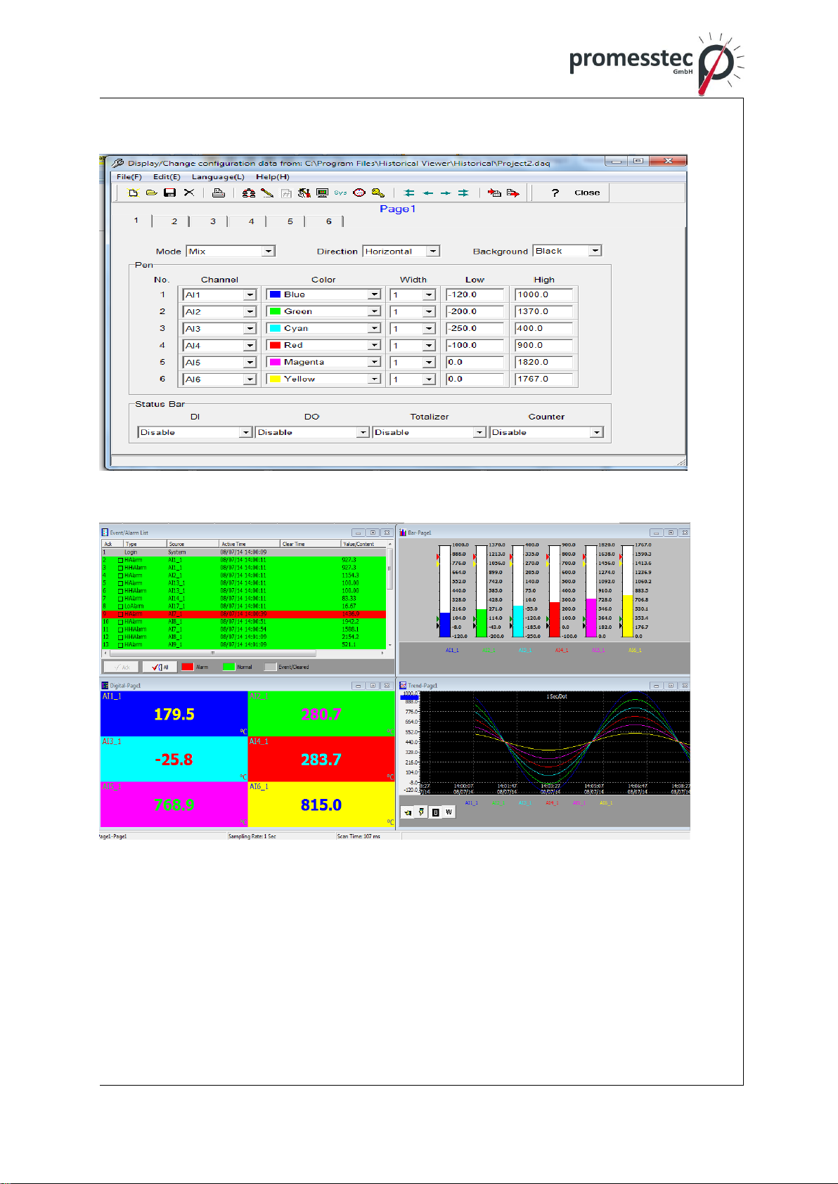
Free Basic software for configuration, Historical viewer
Extensive Software ,Data Acquisition Software for configuration, Historical
viewer and Real time viewer
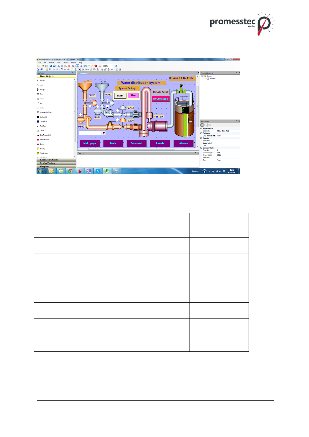
Additional Panel Studio Software for editing customized Displays
Display values in Digital, Real time trends, Historical trends, Bar graphs etc
Real time and Historical alarms
Event management, Jobs linked with events
Reports (Daily, Weekly and Monthly)
Timers, Optional -Counters, Totalizers, Math channels and CFR-21

8
promesstec GmbH I Niedersachsenstraße 4 I D- 48465 Schüttorf I Tel.:+49 (0)5923/ 90 229 0 I Fax:+49 (0)5923/ 90 229 29
E-Mail: office@promesstec.com I Internet: www.promesstec.com
Customized messages for the alarms
Alarms by email directly from paperless recorder
Batch control, log data in batches
100 msec. data logging and historical data archival tools
Display screens rotation
Data dynamic exchange feature via PC software
Search data with reference to time and period and Export to spread sheets
Data logging by value change or time base
Start/Stop data logging functions which can be linked with real time clock or
events
Historical Viewer in Free and Extensive Software:
9
promesstec GmbH I Niedersachsenstraße 4 I D- 48465 Schüttorf I Tel.:+49 (0)5923/ 90 229 0 I Fax:+49 (0)5923/ 90 229 29
E-Mail: office@promesstec.com I Internet: www.promesstec.com
Editing Configuration in Free and Extensive Software:
Extensive Software Data Acquisition Studio with Real-time Viewer:
10
promesstec GmbH I Niedersachsenstraße 4 I D- 48465 Schüttorf I Tel.:+49 (0)5923/ 90 229 0 I Fax:+49 (0)5923/ 90 229 29
E-Mail: office@promesstec.com I Internet: www.promesstec.com
Panel Studio Software to Edit Custom Displays:
4.2 Comparison of PPR series Recorders
Description
PPR200
PPR500
Display Size
6,1”
5.6”
Analog Inputs (Maximum)
18
24
Math Channels (Maximum)
18
40
External Channels (Other de-
vices)
0
48
Total Pages
6
20
Pens/Page (Maximum)
6
6
Batches
(Maximum)
0
1
11
promesstec GmbH I Niedersachsenstraße 4 I D- 48465 Schüttorf I Tel.:+49 (0)5923/ 90 229 0 I Fax:+49 (0)5923/ 90 229 29
E-Mail: office@promesstec.com I Internet: www.promesstec.com
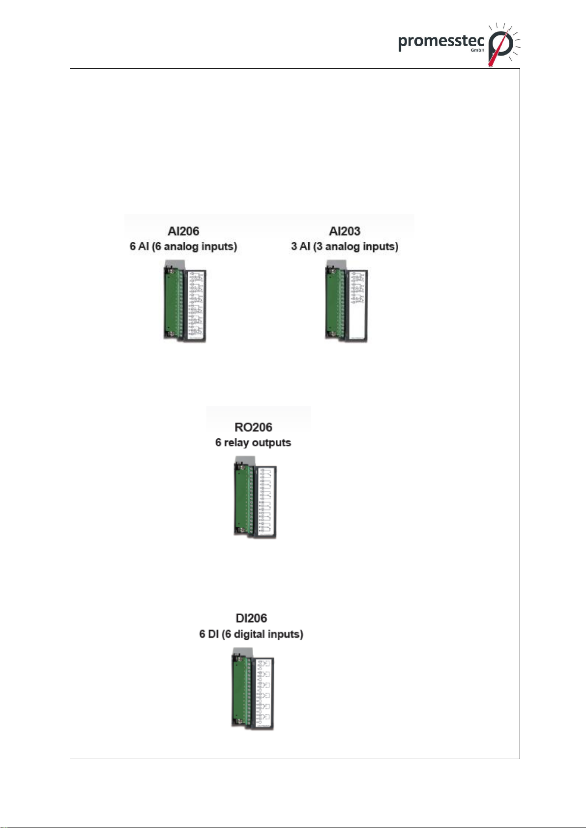
4.3 Expandable Input and Output cards
The recorder is equipped with rear expansion slots, which work flexibly with the
following plug & play I/O cards.
Analog Input cards (part number AI206 & AI203): These two cards are used for
6 & 3-channel analog input. Each input is isolated from each other to avoid noise
and to ensure stable measurement.
Relay Output card (RO206): Each card includes 6 alarm relays. Contacts are rat-
ed 5 Amp/240 VAC
Digital Input card (DI206): Each card includes 6 channels. Logic Low: -5V mini-
mum, 0.8V maximum, Logic High: 3.5V minimum, 24V maximum
12
promesstec GmbH I Niedersachsenstraße 4 I D- 48465 Schüttorf I Tel.:+49 (0)5923/ 90 229 0 I Fax:+49 (0)5923/ 90 229 29
E-Mail: office@promesstec.com I Internet: www.promesstec.com
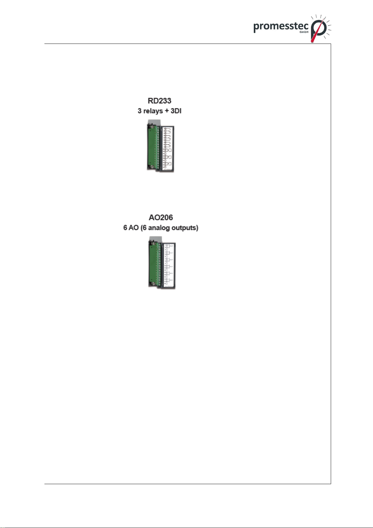
Relay Output and Digital Input Card (RD233): Each Card includes 3-digital In-
puts and 3-Relay Outputs. For Digital Inputs , Logic Low: -5V minimum, 0.8V max-
imum, Logic High: -3.5V minimum, 24V maximum. For Relay Outputs , the Con-
tacts are rated 5 Amp/240 VAC
Analog Output cards (AO206): Each card includes 6 channels. They are used
for 4-20mA, 0-20mA current output, 0-5V, 1-5V, 0-10VDC voltage output.
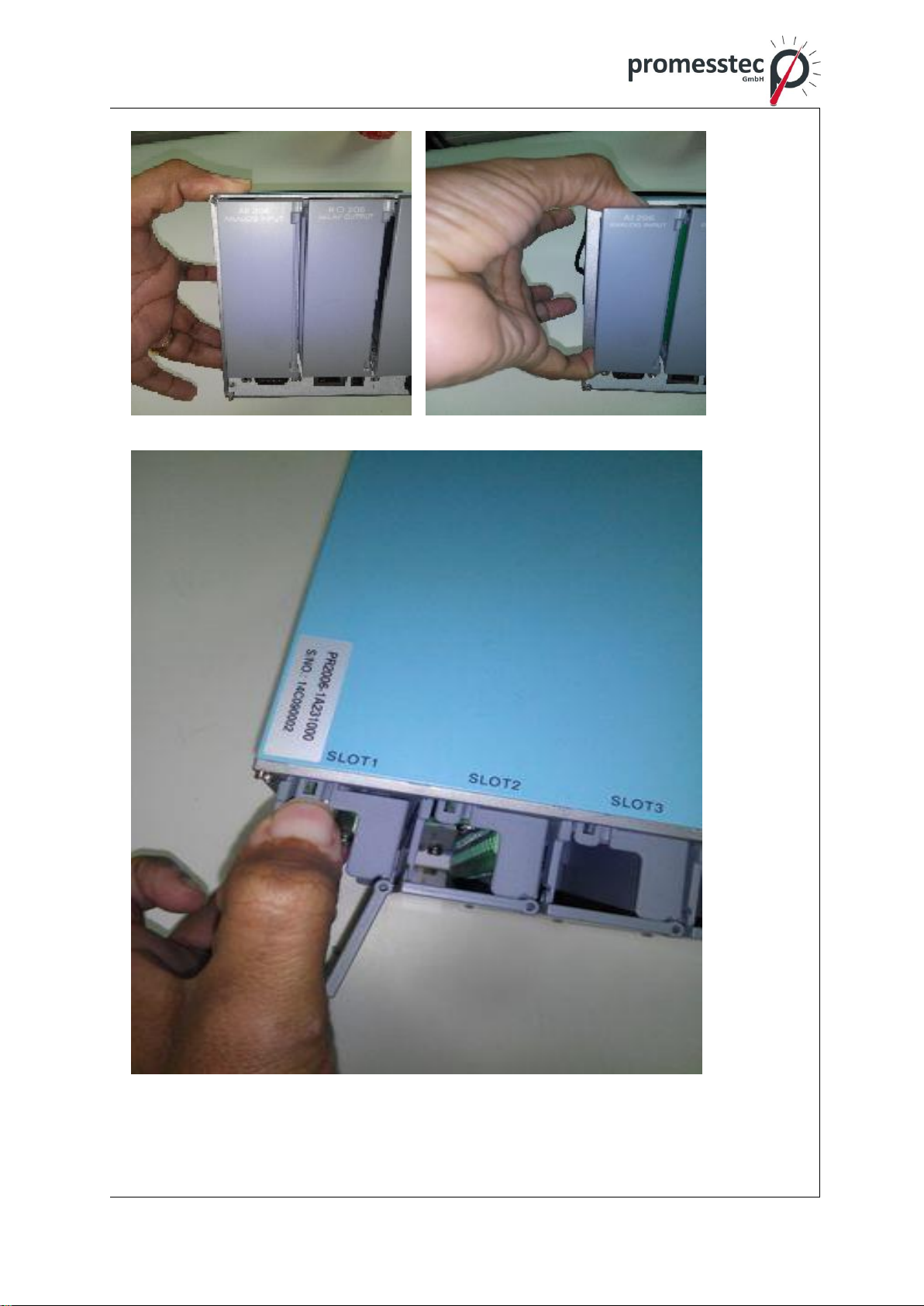
Note 1: The IO Cards should not be removed or Inserted to the PR when the
Power is ON. This should be carried out at Power OFF Condition only.
Note 2: For Thermocouple Inputs, 1 hour inputs warm up is necessary for first ini-
tial set up.
Note 3: Information in regards removing the IO Cards from PR. For removing the
IO Card we need to press the lock on the top and bottom of the IO Card and then
pull to remove it. Failing to do so will damage the IO Cards. Please follow the be-
low pictures for more information.
13
promesstec GmbH I Niedersachsenstraße 4 I D- 48465 Schüttorf I Tel.:+49 (0)5923/ 90 229 0 I Fax:+49 (0)5923/ 90 229 29
E-Mail: office@promesstec.com I Internet: www.promesstec.com

14
promesstec GmbH I Niedersachsenstraße 4 I D- 48465 Schüttorf I Tel.:+49 (0)5923/ 90 229 0 I Fax:+49 (0)5923/ 90 229 29
E-Mail: office@promesstec.com I Internet: www.promesstec.com
4.4 Communication
The standard communication interface is Ethernet with protocol IEEE 802.3 –
10/100 BaseT. other options are RS-232 / RS-422 / RS-485.
4.5 External Storage media
We have got two types External storage Media, SD card and USB for the record-
er. If the recorder is used with 6-channel inputs, an easy chart to show the maxi-
mum days
SD card 16GB 32GB
Log speed
1 second 15808 days 31616 days
10 seconds 158032 days 316064 days
120 seconds 1896304 days 3792608 days
* The above is an approximation
Each record of data uses 2 bytes or 4 bytes of memory.
For ex: Selected data size = 2 bytes
If the Log Speed ( the recording speed of measured data ) is set to the fastest
speed at 1 second per data, then for a six channels, 16GB SD Card will last ap-
proximately 15808 days [= 16GB / ( 2 bytes x 24 hours x 60 minutes x 60 sec-
onds x 6 Channels ].
The following formula is to calculate how many days the USB disk could do sav-
ing before it is full.
The ? days = (The capacity of SD card memory x Log Speed) / ( 2 x no. of
hours per day x 60 x 60 x Number of channels )
If the User is using USB to store data, To avoid losing recorded data while
transferring to PC, it is necessary to insert USB memory back again into the
recorder soon after loading recorded data onto PC.
15
promesstec GmbH I Niedersachsenstraße 4 I D- 48465 Schüttorf I Tel.:+49 (0)5923/ 90 229 0 I Fax:+49 (0)5923/ 90 229 29
E-Mail: office@promesstec.com I Internet: www.promesstec.com
4.6 Smart Mechanism
The recorded data is stored in the manufacturer’s special binary format. It is not
possible to manipulate or modify the recorded data. This feature fully guarantees
the security of the data.
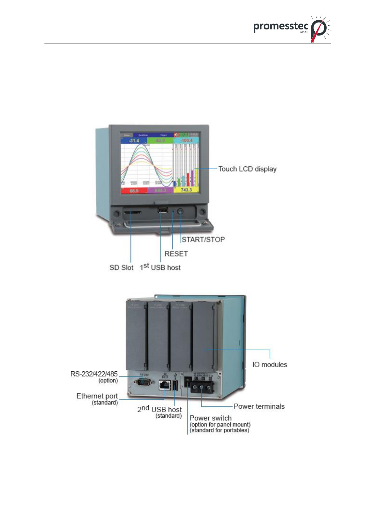
Front View:
Rear View:

16
promesstec GmbH I Niedersachsenstraße 4 I D- 48465 Schüttorf I Tel.:+49 (0)5923/ 90 229 0 I Fax:+49 (0)5923/ 90 229 29
E-Mail: office@promesstec.com I Internet: www.promesstec.com
4.7 Ordering code and accessories
4.7.1 Ordering code PPR 500
Order example: PPR 500-1-A-A-A-A-0-1-0
Power
-1 230VAC
-2 24VDC
Function Slot 1
-A 3 universal inputs analog AI203
-X 6 universal inputs analog AI206
-B 6 digital inputs DI206
-C 6 relay outputs RO206
-E 3 relay outputs and 3 digital inputs RD233
-F 6 universal outputs mA and V
Function Slot 2
-A 3 universal inputs analog AI203
-X 6 universal inputs analog AI206
-B 6 digital inputs DI206
-C 6 relay outputs RO206
-E 3 relay outputs and 3 digital inputs RD233
-F 6 universal outputs mA and V
Function Slot 3
-A 3 universal inputs analog AI203
-X 6 universal inputs analog AI206

17
promesstec GmbH I Niedersachsenstraße 4 I D- 48465 Schüttorf I Tel.:+49 (0)5923/ 90 229 0 I Fax:+49 (0)5923/ 90 229 29
E-Mail: office@promesstec.com I Internet: www.promesstec.com
-B 6 digital inputs DI206
-C 6 relay outputs RO206
-E 3 relay outputs and 3 digital inputs RD233
-F 6 universal outputs mA and V
Function Slot 4
-A 3 universal inputs analog AI203
-X 6 universal inputs analog AI206
-B 6 digital inputs DI206
-C 6 relay outputs RO206
-E 3 relay outputs and 3 digital inputs RD233
-F 6 universal outputs mA and V
Option 1
-0 ethernet
-1 ethernet and RS232
-2 ethernet and RS422/485
Option 2 firmware
-0 standard
-1 standard, math, counter, totalizer, batch, CFR21part11
Option 3 housing
-0 no option 3
-1 bench top portable style with handle

18
promesstec GmbH I Niedersachsenstraße 4 I D- 48465 Schüttorf I Tel.:+49 (0)5923/ 90 229 0 I Fax:+49 (0)5923/ 90 229 29
E-Mail: office@promesstec.com I Internet: www.promesstec.com
4.7.2 Accessories:
Part no. Descriptions
AI203 3-channel analog input card (TC, RTD, mA, V, mV)
AI206 6-channel analog input card (TC, RTD, mA, V, mV)
RO206 6-channel relay output card
DI206 6-channel digital input card
RD233 3-channel Relay output and 3-channel digital input card
AO206 6-channel analog output card
Notes:
The rear Slots of the recorder will only accept optional cards of input, output in
any combination based on selected model.
The basic PC software is supplied free together with recorder. There is an
additional charge for the extensive Data Acquisition Software supplied with
communication of RS-232/422/485 or Ethernet.
4.8 Specifications
Power:
PPR 500:
90-250VAC, 47-63Hz, 52VA, 26W maximum
11-36VDC, 26VA, 26W maximum
Display:
LCD, 640 x 480 pixel resolution, 65K color
Memory:
256MB storage memory on board.
Analog Input Cards (AI20X):
Channels: AI203 ~ 3 channels, AI206 ~ 6 channels
Resolution: 24 bits
Sampling Rate: 10 times/ second
Maximum Rating: RTD input ±20V
T/C and Voltage input ± 65V
mA input ±10V
Temperature Effect: ±0.1uV ±15PPM of reading for all inputs except mA,
±30PPM of reading for mA input
Sensor Lead Resistance Effect:
T/C: 0.32PPM of reading/ohm 3-wire RTD: 2.6 ˚C /ohm of resistance difference
of two leads (Based on ℃measurement temperature for PT100)
2-wire RTD: 2.6 ˚C /ohm of resistance sum of two leads (Based on ℃measure-
ment temperature for PT100)

19
promesstec GmbH I Niedersachsenstraße 4 I D- 48465 Schüttorf I Tel.:+49 (0)5923/ 90 229 0 I Fax:+49 (0)5923/ 90 229 29
E-Mail: office@promesstec.com I Internet: www.promesstec.com
Burn-out Current: 10uA
Common Mode Rejection Ratio (CMRR): 120dB
Normal Mode Rejection Ratio (NMRR): 55dB
Isolation Breakdown Voltage between channels: 1500VAC min.
Sensor Break Detection:
Sensor opened for TC, RTD and mV inputs, below 1 mA for 4-20mA input, below
0.25V for 1-5V inputs, unavailable for other inputs
Sensor Break Responding Time: Within 1 seconds for TC, RTD and mV inputs,
0.1 second for 4-20 mA and 1-5V inputs
Characteristics:
Type Range Accuracy Input
at 25 ˚C Impedance
J -120 ~ 1000 ˚C ±1 ˚C 3.12MΩ
(-184 ~ 1832 ˚F)
K -200 ~ 1370 ˚C ±1 ˚C ˚3.12MΩ
(-328 ~ 2498 ˚F)
T -250 ~ 400˚˚C ±1 ˚C 3.12MΩ
(-418 ~ 752˚F)
E -100 ~ 900 ˚C ±1 ˚C 3.12MΩ
(-148 ~ 1652 ˚F)
B 0 ~ 1820 ˚C ±2 ˚C 3.12MΩ
(32 ~ 3308 ˚F) (200 ~ 1820 ˚C)
R 0 ~ 1768 ˚C ±2 ˚C 3.12MΩ
(32 ~ 3214 ˚F)
S 0 ~ 1768 ˚C ±2 ˚C 3.12MΩ
(32 ~ 3214 ˚F)
N -250 ~ 1300 ˚C ±1 ˚C 3.12MΩ
(-418 ~ 2372 ˚F)
L -200 ~ 900 ˚C ±1 ˚C 3.12MΩ
(-328 ~ 1652 ˚F)
U -200 ~ 600˚C ±1 ˚C 3.12MΩ
(-328 ~ 1112 ˚F)
P 0 ~ 1395 ˚C ±1 ˚C 3.12MΩ
(32~2543 ˚F)
W5 0 ~ 2315 ˚C ±1 ˚C 3.12MΩ
(32 ~ 4199˚F)
W3 0 ~ 2315˚C ±1 ˚C 3.12MΩ
(32 ~ 4199 ˚F)
LR -200 ~ 800 ˚C ±1 ˚C 3.12MΩ
(-328 ~ 1472 ˚F)
A1 0 ~ 2500 ˚C ±1 ˚C 3.12MΩ
(-32 ~ 4532 ˚F)
A2 0 ~ 1800 ˚C ±1 ˚C 3.12MΩ
(-32 ~ 3272 ˚F)
A3 0 ~ 1800 ˚C ±1 ˚C 3.12MΩ
(-32 ~ 3272 ˚F)
M -200 ~ 100 ˚C ±1 ˚C 3.12MΩ
(-328 ~ 212 ˚F)
PT50 -200 ~ 850 ˚C ±0.4 ˚C 2.0KΩ
(α = 0.00385) (-328 ~ 1562 ˚F)
PT100 -200 ~ 850 ˚C ±0.4 ˚C 2.0KΩ

20
promesstec GmbH I Niedersachsenstraße 4 I D- 48465 Schüttorf I Tel.:+49 (0)5923/ 90 229 0 I Fax:+49 (0)5923/ 90 229 29
E-Mail: office@promesstec.com I Internet: www.promesstec.com
(α = 0.00385) (-328~ 1562 ˚F)
PT200 -200 ~ 850 ˚C ±0.4 ˚C 2.0KΩ
(α = 0.00385) (-328 ~ 1562 ˚F)
PT500 -200 ~ 850 ˚C ±0.4 ˚C 2.0KΩ
(α = 0.00385) (-328 ~ 1562 ˚F)
PT1000 -200 ~ 350 ˚C ±0.4 ˚C 2.0KΩ
(α = 0.00385) (-328 ~ 662 ˚F)
PT50 -200 ~ 850 ˚C ±0.4 ˚C 2.0KΩ
(α = 0.00391) (-328 ~ 1562 ˚F)
PT100 -200 ~ 850 ˚C ±0.4 ˚C 2.0KΩ
(α = 0.00391) (-328 ~ 1562 ˚F)
JPT50 -200 ~ 600 ˚C ±0.4 ˚C 2.0KΩ
(α = 0.003916) (-328 ~ 1112 ˚F)
JPT100 -200 ~ 600 ˚C ±0.4 ˚C 2.0KΩ
(α = 0.003961) (-328 ~ 1112 ˚F)
JPT200 -200 ~ 600 ˚C ±0.4 ˚C 2.0KΩ
(α = 0.003916) (-328 ~ 1112 ˚F)
JPT500 -200 ~ 600 ˚C ±0.4 ˚C 2.0KΩ
(α = 0.003916) (-328 ~ 1112 ˚F)
JPT1000 -200 ~ 350 ˚C ±0.4 ˚C 2.0KΩ
(α = 0.003916) (-328 ~ 662 ˚F)
Cu50 -50 ~ 200 ˚C ±0.4 ˚C 2.0KΩ
(α = 0.00426) (-58 ~392 ˚F)
Cu100 -50 ~ 200 ˚C ±0.4 ˚C 2.0KΩ
(α = 0.00426) (-58 ~392 ˚F)
Cu50 -180 ~ 200 ˚C ±0.4 ˚C 2.0KΩ
(α = 0.00428) (-292 ~392 ˚F)
Cu100 -180 ~ 200 ˚C ±0.4 ˚C 2.0KΩ
(α = 0.00428) (-292 ~392 ˚F)
Ni100 -60 ~ 180 ˚C ±0.4 ˚C 2.0KΩ
(α = 0.00617) (-76 ~356 ˚F)
Ni200 -60 ~ 180 ˚C ±0.4 ˚C 2.0KΩ
(α = 0.00617) (-76 ~356 ˚F)
Ni500 -60 ~ 180 ˚C ±0.4 ˚C 2.0KΩ
(α = 0.00617) (-76 ~356 ˚F)
Ni1000 -60 ~ 180 ˚C ±0.4 ˚C 2.0KΩ
(α = 0.00617) (-76 ~356 ˚F)
Cu10 -200 ~ 260 ˚C ±1.0 ˚C 2.0KΩ
(α= 0.00427) (-328 ~500 ˚F)
+-20mA -26 ~ 26mA ±0.05% 75Ω
+-60mV -122~122mV ±0.05% 3.12MΩ
+-200mV -243~243mV ±0.05% 3.12MΩ
+-1V -1.58~1.58V ±0.05% 3.12MΩ
+-2V -3.16 ~ 3.16V ±0.05% 3.12MΩ
+-6V -6.32 ~ 6.32V ±0.05% 3.12MΩ
+-20V -25.3 ~ 25.3V ±0.05% 3.12MΩ
+-50V -50.6 ~ 50.6V ±0.05% 3.12MΩ
0.4 ~ 2V -3.16 ~ 3.16V ±0.05% 3.12MΩ
1~5V -6.32 ~ 6.32V ±0.05% 3.12MΩ
Table of contents


