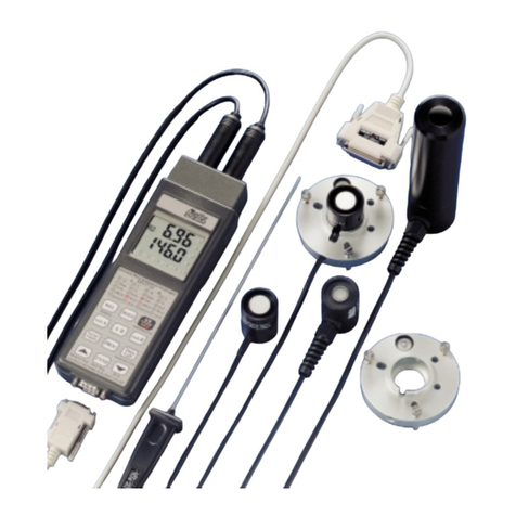
Delta OHM DO 9847K User manual

DO 9847K
STRUMENTO MULTIFUNZIONE PORTATILE DATA-LOGGER
PORTABLE MULTIFUCTION DATA-LOGGER INSTRUMENT
INSTRUMENT PORTATIF MULTIFONCTION COLLECTEUR DE DONNÉES
TRAGBARES MULTIFUNKTIONSGERÄT DATALOGGER
INSTRUMENTO MULTIFUNCION PORTABLE DATALOGGER
It measures
Temperature
Relative humidity
Pressure:
Barometric
Absolute
Differential
Air speed and ow rate:
Hot-wire
Vane
Pitot tube
Disconfort Index
Photometry-Radiometry
mV - mA

- 2 -
Ti
A1
b1
c1
1
2
3
4
5
6
7
8
9
10
11
12
13
14
15
16
17 18
19
20
21
22
23
24
25
26
27
28
29
30
31
32
33

- -
3
1. Input B, DIN 45326 8-pole connector
2. Input A, DIN 45326 8-pole connector
3. Battery symbol: indicates the battery charge level
4. First display line (line X)
5. Third display line (line Z)
6. Key <F2>: activates the central command on the controls bar
7. Key <F1>: activates the left-hand command on the controls bar
8. Key <MENU>: displays the instrument’s functions menu
9. Key <ESC/CLR>: allows you to move about in the menu, passing to the higher level; cancels
the current operation without modifying the instrument parameters. It clears the peak value re-
lated to pressure measurements.
10. Key <7/HOLD>: in the menu it writes the number 7; in normal operation it freezes the meas-
urement.
11. Key <5/DATA CALL>: in the menu it writes the number 5; in normal operation it recalls the
minimum (key <F1>), maximum (key <F2>) and mean (key <F3>) value of the three inputs
12. Key <4/SERIALOUT>: in the menu it writes the number 4; in normal operation it activates the
menu for the "Serial output" function
13. Key <1/MATH>: in the menu it writes the number 1; in normal operation it activates the func-
tion that manages mathematical operations
14. Key <.> (decimal point): in the menu it writes the decimal point. When pressed after the
<MENU> key, it switches over the instrument’s Auto Power Off function.
15. Key <0>: in the menu it writes the number zero. In measurement mode, it adjusts the offset of
probes provided with this function.
16. Key <LEFT/UP>: in the menu it shifts the cursor up or to the left, in measurement it increases
the display contrast
17. RS232C 9-pole connector
18. External auxiliary power supply connector
19. Key <RIGHT/DOWN>: in the menu it shifts the cursor down or to the right; in measurement it
decreases the display contrast
20. Key <ENTER>: in the menu it accepts the active function. In measurement mode, it provides or
cuts off power supply to the hot-wire probe.
21. Key <+/->: in the menu it inserts the "-" sign in front of a number. Using the SICRAM module
PP471 for pressure probes TP704 and TP705, it activates and deactivates the relative function.
22. Key <3/TIME>: in the menu it writes the number 3; in normal operation it activates the menu
for the Time function
23. Key <2/LOG>: in the menu it writes the number 2; in normal operation it activates the menu for
the Logging function
24. Key <6/RCD>: in the menu it writes the number 6; in normal operation it activates the menu for
the Record function
25. Key <9/UNIT>: in the menu it writes the number 9; in normal operation activates the menu for
selecting the unit of measurement for the three inputs
26. Key <8/REL>: displays the difference between the current value and the one stored the moment
the key was pressed
27. Key <ON/OFF>: switches the instrument on and off
28. Key <F3>: activates the right-hand command on the controls bar
29. Controls bar (the indications vary according to the active function)
30. Second display line (line Y)
31. Indications of the active functions
32. Internal temperature indication
33. Input C, DIN 45326 8-pole connector
REV. 3.1
June 15th 2009

- -
4
INTRODUCTION
•Portable multifunction instrument
•Datalogger with immediate or delayed start of logging (programming of autostart
and autostop)
•Large graphic display (56x38mm) with adjustable contrast
•Intelligent probes with automatic recognition: they store the factory and user cali-
bration data
•Possibility of using factory or user calibration
•Functions: Record, Logging, difference between two channels, relative measure-
ment, hold, …
•Reserved functions with user password
•Standard RS232C serial port
•Immediate printing of the measured values or of their differences with indications
of the max, min and mean (avg) values of each channel
•Automatic shut-off which may be excluded
•Selectable units of measurement
•Updating of firmware may be carried out through the via RS232C serial port
This manual relates to DO9847, version 3.0. Prior versions of DO9847 are not
provided with some of the functions described in this manual.

- -
5
KEYBOARD DESCRIPTION
ON/OFFKey
To switch the instrument on and off, hold down the ON/OFF key for at least one second. When
switching on the instrument checks what probes are connected to its inputs: if any variations have
occurred with respect to the previous measuring session, the opening screen appears with the soft-
ware version and, after a few moments, the instrument goes into standard measuring condition dis-
playing the channels set just as the switching off.
Ti
A1
b1
c1
34
6
If there has been a variation because, for example, a probe has been disconnected, the following
message appears: “WARNING! CHANGE OF PROBES DETECTED – Press NOW any key to
choose settings or wait self-config”. When any key is pressed within 3 seconds the menu is opened
in which the instrument configuration parameters may be modified. If you do not think it is neces-
sary to alter them, just wait 3 seconds, afterwards the instrument return automatically to standard
measuring conditions with the indications of the first free channels available among A1, B1, C1,
A2, B2, C2, A3, B3, C3 and Ti.
3 sec
If, for example, a module for measuring the combined humidity and temperature is connected to the
input A and a module Pt100 to the input B, the automatic configuration arranges the display in this
way: first line %R.H. (A1), second line temperature of the Pt100 probe (B1), third line temperature
of the combined probe (A2). If no module is connected to any input, Ti internal temperature will be
viewed.
The instrument has an automatic shut-off function (AutoPowerOff) which automatically switches
off the instrument after 8 minutes with the batteries fully charged or after 1 minute with the batter-
ies partly charged, if no key has been pressed in this interval. The AutoPowerOff function may be
disabled by pressing the keys <MENU> and then < DECIMAL POINT>: in this case a letter B(Bat-
tery) flashes to remind the user that the instrument will not switch off automatically but only when
the <ON/OFF> key is pressed. The automatic shut-off function is disabled when using an external
source of power. When batteries are flat, this function cannot be disabled.
ON/OFF

- -
6
MENUKey
When the <MENU> key is pressed, a warning appears to remind the user that this function blocks
the measurement and logging operations.
Press:
<ENTER>to access the menu or
<ESC/CLR>to return to measuring mode without terminating the current operations or
<. > (decimal point) to toggle the automatic shut-off function (AutoPowerOff) of the instru-
ment. The function is not active, so the instrument does not switch off
automatically if the flashing letter Bis present at the top of the display.
From the MENU screen, pressing the number to the left of each item, it is possible to access the fol-
lowing sub-functions (for details see page 15 and following):
01
23
45
7
9
6
8
0) Info collects information about the firmware version, the serial number and the last calibra-
tion date of the instrument and of the connected probes.
1) Config for managing the reserved functions with password.
2) Logging for setting the logging parameters.
3) Time/date for setting or modifying the current date and time.
4) Serial for setting the baud rate of the RS232C serial port and the printing interval (in sec-
onds).
5) Calibrate for calibrating the instrument and the probes. The calibration of the combined
“probe + instrument” may be protected with a user password.
6) Reset to return the instrument parameters to default conditions (date, time, configurable op-
tions protected by password, baud rate, printing interval, logging functions).
7) Utility makes a list of calculating instruments and functions related to some specific modules.
8) Options sets reference calculating parameters related to some modules.
9) More jumps to the next page of the menu.
MENU

- -
7
ESC/CLRKey
In the menu, it cancels or annuls the active function. In measurement, it cancels the active function
that appears on the controls bar (bottom line of the display) and returns the instrument display to the
basic screen with the functions Xsel, Ysel and Zsel on the controls bar.
Key0
In the menu it writes the number zero. In measurement mode, it sets to zero the difference between
the inputs of differential pressure probes and adjusts the zero point in hot wire and Pitot tube
probes.
Key1/MATH
In the menu it writes the number 1; in measurement, it manages mathematical operations and data
handling.
Key2/LOG
In the menu it writes the number 2; in measurement, it starts the Logging function using the pa-
rameters set in the menu under the heading "Logging".
Starting from the measuring screen, when the key <2/LOG> is pressed, the two logging functions
appears on the controls bar: when the <F1>SCREEN key is pressed, data logging will start just as
the data appear on the display at that moment; when the ALL<F3> key is pressed, all the variable of
the three input channels are logged (A1, A2, A3, B1,…,C2, C3 and the internal temperature Ti).
Ti
A1
b1
c1
Ti
A1
b1
c1
ESC/CLR
1
MATH
2
LOG
0

- -
8
As long as the logging function is active, the indications Band L flash on the display or only Lif
the instrument is using an external power supply.
To conclude the logging operation, it is sufficient to press the StopLog <F2> key.
If after having pressed the key <2/LOG>, you do not want to proceed with the logging operation it
is sufficient to press the <ESC/CLR> key to return to normal measurement.
The same logging function may be started and stopped at a fixed time and date (see the Logging
function on page 88 and the respective settings on page 17).
Key3/TIME
In the menu it writes the number 3; in measurement it displays
the current time and date in the year/month/day format. The in-
dication disappears about 5 seconds after pressing the key
<3/Time>. The date and time may be modified in point 3) of the
menu: Time/date (see page 22).
A1
b1
c1
Key4/SERIALOUT
In the menu it writes the number 4; in measurement it enables the submenu for managing the opera-
tions connected with the RS232C serial output; the data are printed in table form. The functions that
can be activated with the three function keys F1, F2 and F3 are:
Screen – key <F1>– unlimited continuous printing of the data just as they are shown on the display
at the time of starting the function,
RCD+ – key <F2> – same as Screen function, plus the indication of the maximum, minimum and
mean values up to a maximum of 100,000 samples,
ALL – key <F3 >– prints the 9 quantities A1, A2, …, C2, C3 and the internal temperature.
If an external power source is connected, letters Pand B, or letter P only, flash as soon as the
Screen function or the ALL function is started; when the RCD+ function is started, letters B, Pand
Rflash and, while, in case an external power supplier is connected, letters Pand Rwill flash. if an
external power source is connected.
To conclude the operation in progress, press the stop key F1 (see p. 86 and following).
Ti
A1
b1
c1
Ti
A1
b1
c1
3
TIME
4
SERIAL
OUT

- -
9
Key5/DATACALL
In the menu it writes the number 5; in measurement it allows you
to call up the maximum (max), minimum (min) and mean (avg)
values of the data acquired by the three channels and stored with
the RCD function (key <6/RCD>). The function is active only if
some data have been logged previously or if the Record function
is active at that time. In this case, the display appears as in the fig-
ure alongside, otherwise there is the message:
no records available
Ti
A1
b1
c1
To return to normal measurement, press the function key next to the indication norm.
Key 6 / RCD
In the menu it writes the number 6; in measurement it enables the
submenu for the Record function which stores the maximum, mean
and minimum values of the three channels. The function <F1
>
(rcdGO) starts logging at a rate of one sample per second (the sym-
bols Band R– or only Rif an external power source is connected
– flash on the display). The function<F2>M(n=00) stores a sample
each time the F2 key is pressed (the symbols Band M– or only M
if an external power source is connected – flash on
Ti
A1
b1
c1
the display). The function <F3> (rcdCLR) cancels the previously recorded data and the function
<F2> (rcdSTOP) stops recording started with rcdGO.The stored data may be called up using the
DataCall function, key <5/DATA CALL> (see p.86).
Key7/HOLD
In the menu it writes the number 7; in measurement it freezes the measurement in progress the
moment the key is pressed. The message HOLD appears at the top of the display. Press the key
again to return to normal measurement.
5
DATA
CALL
6
RCD
7
HOLD

- -
10
Key8/REL
In the menu it writes the number 8; in measurement it displays, for the three channels, the differ-
ence between the current value and the one measured at the time the key was pressed. The mes-
sage REL appears at the top of the display; press the key again to return to normal measurement.
Key9/UNIT
In the menu it writes the number 9. In measurement it displays the
submenu from which it is possible to choose the unit of measure-
ment of the quantities at input. F1 (unitX) refers to the measure-
ment which appears on the first line of the display, F2 (unitY) to the
measurement which appears on the second line and F3 (unitZ) to
the third. When the function key is pressed repeatedly, the possible
units are presented: for example, if the measurement taken by a
temperature probe connected to the instrument appears on the first
Ti
A1
b1
c1
line of the display, when the function key F1 is pressed the measurement will be displayed in °C, in
°F and in °K. When the key F1 is pressed again the measurement will return to in °C. If only one
unit of measurement is contemplated, pressing the respective key will produce no consequence. The
setting influences all that is shown on the display and the immediate printing of data (key
<4/SERIALOUT>). The data stored with the LOG (logging) function keep the units of measure-
ment chosen at the time of recording.
“.” / Decimal point Key
In the menu it writes the decimal point. When pressed after the <MENU> key, it toggles the instru-
ment’s automatic shut-off function AutoPowerOff.
“+/-”Key
In the menu it allows you to insert the “-“ sign in front of a number or in a mathematical function.
Activates and deactivates the relative function with SICRAM module PP471 for TP704 and TP705
pressure probes.
+/-
8
REL
9
UNIT
.

- -
11
Up/LeftKey
Key for shifting the cursor during data input in the menu and for regulating the display contrast: if
the key is pressed, when outside the menu, it increases the display contrast.
ENTERKey
Key for confirming the active function. To increase battery life, it applies and turns off power sup-
ply to the hot wire probes, when connected.
Down/RightKey
Key for shifting the cursor during data input in the menu and for regulating the display contrast: if
the key is pressed, when outside the menu, it decreases the display contrast.
FunctionkeyF1
Function key F1. The function performed by this key varies according to the active operation. (For
the Xsel function see the paragraph “Xsel, Ysel and Zsel commands” )
FunctionkeyF2
Function key F2. The function performed by this key varies according to the active operation. (For
the Ysel function see the paragraph “Xsel, Ysel and Zsel commands” )
FunctionkeyF3
Function key F3. The function performed by this key varies according to the active operation. (For
the Zsel function see the paragraph “Xsel, Ysel and Zsel commands” )
F1
ENTER
F2
F3

- -
12
Use of the <Hold> key
Ti
A1
b1
c1
CURRENT MEASUREMENT
Æpress
A1
b1
c1
MEASUREMENT “FROZEN”
the message “HOLD” appears
the values on the display are not updated
Æpress
Ti
A1
b1
c1
CURRENT MEASUREMENT
7
H
O
LD
7
H
O
LD

- -
13
Use of the <REL> key
Ti
A1
b1
c1
CURRENT MEASUREMENT
Æpress
A1
b1
c1
The display shows the relative measurement, equal
to zero if the input signal has not varied in the mean-
time.
A1
b1
c1
The display shows the relative measurement. Chan-
nels A and C have increased, channel B has de-
creased.
Æpress
Ti
A1
b1
c1
CURRENT MEASUREMENT
8
REL
8
REL

- -
14
XSEL,YSEL AND ZSEL COMMANDS
In the basic display, the function F1 is associated with the Xsel command. With this command it is
possible to set the variable that is to appear on the first line of the display: this variable refers to all
three inputs of the instrument. Each probe has a maximum of three variables: for example, in the
SICRAM module TP471D1 with two thermocouple inputs connected to connector A of the instru-
ment, A1 represents the first thermocouple, A2 the second and A3 the sensor which measures the
temperature of the cold junction. If you press F1 (Xsel) repeatedly, the first line of the display will
show either all available variables, according to the modules connected to the instrument inputs, or
the instrument internal temperature (Ti), or no measurement. In this case, the “>>” symbol will ap-
pear on the left side of the instrument. In addition to the variables associated with each probe (A1,
A2, A3, B1, … , C3), you can also select the difference between two of the three inputs identified
with the number 1 (A1-B1, A1-C1 and B1-C1). The difference between two inputs is available only
if probes of the same type are connected to these inputs, for example two thermocouples, two rela-
tive humidity probes, two Pt100. The difference between different types of probes is not available,
even if they refer to the same physical quantity: for example the difference between a Pt100 and a
thermocouple, even they both measure temperature, as well as the difference between two pressure
probes having a different full scale.
Associated with the functions F2 and F3 are the Ysel and Zsel commands are used to set respec-
tively the variables on the second and the third line of the display.
Ti
A1
b1-C1
c3
F1
F1
F2
F2
F3
F3
A
BC
X row
Y row
Z row
Controls bar
INPUTS

- -
15
DESCRIPTION OFTHE MENU FUNCTIONS
The menu contains all the functions by means of which the parameters for instrument operation are
set.
When the <MENU> key is pressed, the instrument informs the user that, on entering the menu, any
Measuring and Logging functions in progress will be terminated. To return to the menu without los-
ing data, press <ESC>.
The < DECIMAL POINT > key, pressed after the <MENU> key, toggles the automatic shut-off
function (AutoPowerOff). When the function is not active and an external source of power is not
connected, a letter Bflashes at the top of the display: in this case the instrument does not switch off
automatically after 8 minutes of inactivity.
01
23
45
7
9
6
8
The basic menu screen (shown in the square on the right of the figure) supplies the list of the vari-
ous functions.
To access each item in the menu, press the key corresponding to the number shown in front of
each function.
0) INFO (Information)
The Info function provides information about firmware, serial number and date of calibration of
both the instrument and the connected probes. Press Enter to jump from the first to the second
visual display.
Press the <ESC/CLR> key to quit and return to the basic menu screen.
0
2002/03/02
2002/01/01
2002/02/11
user
01
23
45
7
9
6
8
1) CONFIG (Configurations)
Manages the reserved functions with password.
Some instrument functions may be protected with a password: for example access to calibration
of the probes and/or the instrument, modifying the date and/or the time, …
1-1) Reserved Function Lock
There are two levels of password protection: factory level and user level. Each is protected
with the respective password: the factory level is used to protect certain basic functions of the
instrument and for this reason it is not accessible to the user. When the instrument leaves the
production line or after calibration in the factory, it is protected by a factory password; on the
other hand, access to the functions reserved for the user is enabled. To change the enabled or

- -
16
disabled status of the reserved functions, type in the user password and then confirm it with
the <ENTER> key. To quit the function without making any changes, press the clear key
<ESC/CLR>.
1 1
<ESC> exit/cancel
01
23
45
7
9
6
8
1-2) Change password
To change the user password:
A) enable the reserved functions, if this has not been done, by typing in the present password
in point 1) of the Config submenu (see the previous point: Reserved function lock)
B) use the function of the Change password menu to type in the new password: type the 8
figures and then confirm with the <ENTER> key. To quit the function without making any
changes, press the clear key <ESC/CLR>.
Note: when the instrument is switched on for the first time, after changing the batteries or af-
ter reset, the user password is automatically set at 12345678.
1 2
<ESC> exit/cancel
12345678
If user level is enabled, current password is proposed
01
23
45
7
9
6
8
1-3) Probe options
If enabled by a password, this function allows you to configure the type of calibration of each
probe present at the instrument inputs. The standard procedure is as follows: the instrument
detects the presence of a probe at one of its inputs and reads its calibration data.
Serial numbers of the probes connected to the instruments
1 3
01
23
45
7
9
6
8
If the probe contains only factory calibration data (indicated with the code “0 factory”), the
instrument will use these parameters.
If user calibration data are also present in the probe (indicated with the code “1 user”), the
user calibration will be used only if it has been carried out with the same instrument and not
with another one.

- -
17
This standard rule may be modified by configuring the instrument so as to use one type of
calibration rather than another.
0) factory: the probe, connected to the instrument input, will use the factory calibration values
inserted in the probe memory before sale or after recalibration in the factory, even if a user
calibration carried out with the same instrument is present. this choice is useful, for exam-
ple, if there are doubts as to the correctness of the user calibration.
1) user: the calibration values used are those referring to a user calibration even if they were
obtained with a different instrument. If these are not present, for example because the
probe is new, the instrument will use the factory values.
To modify the type of calibration of a probe, select it, choose the new type of calibration and
then confirm with the <ENTER> key.
In the example below, the probe connected to input A uses the factory calibration and is con-
figured so as use the user calibration.
11
<ESC> exit/cancel
Current type of calibration ( factory)
of the probe connected to input A
To quit the function without making any changes, press the clear key <ESC/CLR> instead of
the <ENTER> key.
2) LOGGING
The Logging heading comprises the settings of the function for storing the data at instrument in-
put, which may be activated by means of the LOG function (key <2/LOG>).
To access each item in the menu, press the key corresponding to the number shown in front of
each function.
2
<ESC> exit/cancel
key 0: log interval
key 1: self shut-off mode
key 2: automatic start and stop time
key 3: cancel automatic start
key 4: log file manager
01
23
45
7
9
6
8
2-0) Log Interval
This is the time interval between two consecutive logging sessions. To set a new interval, on
the menu select the item Logging with the key <2/LOG> and then the function Log interval
with the key <0>; type in the new interval – from 0001 to 3600 – and then confirm with the
<ENTER> key.
To quit the function without making any changes, press the clear key <ESC/CLR>

- -
18
2 0
01
23
45
7
9
6
8
2-1) Self shut-off mode
The instrument switches itself off automatically during logging between one sample acquisi-
tion and the next.
2 1
<ESC> exit/cancel
<ESC> exit/cancel
...stay on... or ...shut off...
01
23
45
7
9
6
8
If the logging interval is less than 60 seconds, the instrument will always stay on. For inter-
vals of 60 seconds or more, it is possible to choose to switch off the instrument between two
consecutive logging sessions: the instrument will switch during sampling and then switch off
immediately afterwards, thus prolonging the life of the batteries. The <1/MATH> key toggles
the function: always on (…stay on…) or on/off (…shut off…). To set the desired type of op-
eration, from the menu press the key <2/LOG> to Enter the Logging sub-menu, then press the
key <1/MATH> to activate the window for the Self shut_off mode sub-function. With the key
<1/MATH>, choose the desired type of operation always on (…stay on…) or on/off
(…shut off…) – and then quit pressing the <ESC/CLR> key.
2-2) Start/stop time
Starting and stopping of logging may be programmed by typing in the date and the time.
When it is called, the function proposes, as start time, the current time increased by 5 minutes:
to confirm press <ENTER>, otherwise set the date and time using the arrows. When asked to
set the data for the end of logging: by default the instrument proposes the start time increased
by 10 minutes. To confirm press <ENTER>, otherwise set the date and time using the arrows
and press <ENTER>. At the next screen the variables to be stored have to be selected: press
SCREEN to select the three variables which appear on the display, select ALL to store all the
variables (A1,…C3) and the internal temperature.
The instrument proposes the setting just made: press <ENTER> to confirm it or <ESC> to re-
fuse it. The letter “s” flashing on the display reminds you that the logging operation has been
programmed.

- -
19
2 2
<ESC> exit/cancel
<ESC> exit/cancel
<ESC> exit/cancel
Start time Stop time
01
23
45
7
9
6
8
2-3) Cancel auto start
This function allows you to check the setting of the starting and stopping of logging and, if
necessary, to cancel the operation. After having viewed the settings, to quit leaving the
autostart operation active, press <ESC>. To cancel the operation, press the key <1/MATH>.
2
1
3
<ESC> exit/cancel
Cancelling automatic start and stop
Start programmed for 2001/01/01at 12.05
Stop programmed for 2001/01/01at 12.15
Press the key <1/MATH> to cancelthe operation
Press <ESC/CLR> to quit without cancelling
the operation.
01
23
45
7
9
6
8

- -
20
2-4) Log File Manager
Manages the files of logged data. Whenever a logging session is started (with the key
<2/LOG>), the instrument opens a new file with which it associates the date, the start time
and a number from 00 to 15: in this file are saved all the measurements acquired until the end
of the logging session. The file is composed of pages: each page can contain up to 16 data
(one datum corresponds to a measurement of the three variables which appear on the display)
on SCREEN logging mode while, on ALL mode each page contain up to 5 data (each data
corresponds to a measurement of all variables A1,…, C3 and the internal temperature). Up to
16 different data files are contemplated corresponding to 16 different logging sessions. The
size of the instrument’s memory guarantees a maximum of 2000 total pages for the 16 files,
without any restraint for the size of each file. When the limit of 2000 pages or of 16 logged
files is reached and you start a new logging session, the instrument generates a warning:
“WARNING: MEMORY FULL!!” In this case, before proceeding, you must delete at least
one of the log files.
2 4
<ESC> exit/cancel
<ESC> exit/cancel
01
23
45
7
9
6
8
The function 2-4) Log file manager is subdivided into 4 sub-functions with which it is possi-
ble to see, print or delete the log files.
2-4-0) Print Selected Log
0
<ESC> exit/cancel
PRINT A FILE
This function allows you to select and print a file of logged data. To select a file, use the
arrows to shift to the numbers from 00 to 15. A file is associated with each number: when
selected, the date, time and dimensions of the file appear in the two lines at the bottom of
the display. Attention: there is no time relationship between the number associated with the
file and the date of the file: a lower number does not mean that the file is older. Each file is
identified only by its date and time. To help the user, when entering the print and dis-
play functions the most recent file is proposed while in the delete functions the oldest
file is proposed.
In the example shown above, file 09 is selected: logging was started at 10:03 on 12 March
2001 and the file contains 3 pages of data. To print it, it is sufficient to set up the computer
or the printer (see the chapter “THE FUNCTIONS OF STORING AND
TRANSFERRING DATA TO A PERSONAL COMPUTER” on p. 86) and press the
<ENTER> key. At the end of printing, press <ESC/CLR> to return to the File Manager.
This manual suits for next models
1
Table of contents
Other Delta OHM Data Logger manuals
Delta OHM
Delta OHM HD32MT.1 User manual

Delta OHM
Delta OHM HD30.1 User manual

Delta OHM
Delta OHM HD37B17D User manual
Delta OHM
Delta OHM HD32.8.8 User manual
Delta OHM
Delta OHM HD2013-DB User manual
Delta OHM
Delta OHM HD 2013 Series User manual
Delta OHM
Delta OHM HD35 Series User manual

Delta OHM
Delta OHM HD32.1 User manual

Delta OHM
Delta OHM HD50CR-AS User manual

Delta OHM
Delta OHM HD33M-MB.2 User manual

