ProRac FGWR054-1A User manual
17.
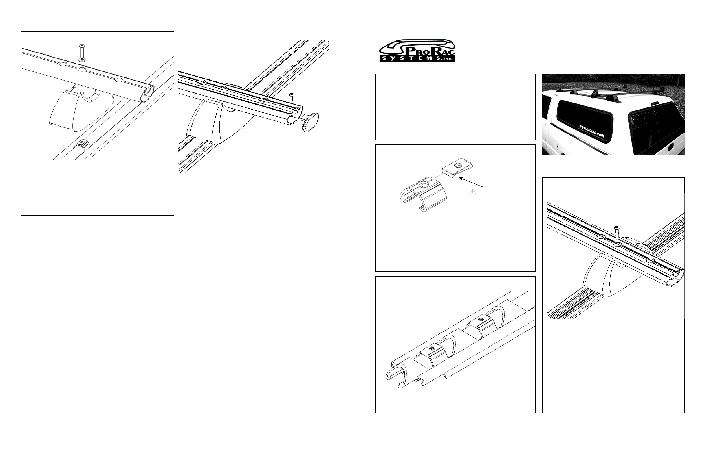
Attach end caps by screwing the 1/4-20 X 9/16" narrow shoulder hex
screw through the threaded end cap and into the hole in the load bar
using the provided ProRac hex wrench.
16.
1.
Attach the U-clips to the four sliding rack anchors.
Work Rack Installation Instructions
54” and 72” Load Bars
ProRac Systems Inc.
7109 31st Avenue North
Minneapolis, MN 55427-2848
Toll Free: 1-800-217-7133
Phone: 763-546-5620
Fax: 763-546-0933
WWW.PRORAC.COM
Package Contents:
(2) 54” or 72” Load Bar (4) 1/4 Split Washers
(1) Lo Pro Track Kit (12) Flanged Washers
(4) 1/4-20 X 2-1/4” Button Head Screws (12) Cap Covers
(12)1/4-20 X 1-1/2” Button Head Screws (4) Feet
(4) End Caps (6) Sliding Tie Downs
(1) Hex Wrench (1) 3 oz tube Silicone
(4) U-Clips (4) Sliding Rack Anchors
(12) 1/4-20 Nuts with Integral Lock Washers
(4) 1/4-20 X 9/16" Narrow Shoulder Hex Screws
Photo shown with optional sliding load stops and 72” load bars.
Place the ¼” split washer onto the 1/4-20 x 2-1/4” screw.
Position the load bar and selected mounting hole over the foot and
sliding anchor.
3.
Make certain that
the U-clip is oriented
as shown!!!
Slide the 1/4-20 x 2-1/4” screw with the ¼” split washer through the
load bar and foot and screw into the sliding anchor using the provided
ProRac hex wrench.
PRO RAC GUIDELINES
2.
Please review the instructions and warranty carefully. Assembly and installation are the purchaser’s responsibility and beyond ProRac’s control.
Therefore, ProRac exclusively limits its warranty to the repair or replacement of a defective ProRac product for up to three years from retail
purchase. Warranty excludes damage to your vehicle, cargo, or any person or property during assembly, installation, and use.
♦Do not carry more than 150 pounds (68KG) of combined cargo and accessories on ProRac load bars. ProRac load bars do not increase
gutter or roof strength. ProRac cannot warranty loads that exceed this limit.
♦Do not use ProRac load bars and accessories for purposes other than those for which they were designed. Do not exceed their carrying
capacity. Failure to follow these guidelines or the product instructions will void the warranty.
This step is performed on a workbench or floor, not on a vehicle.
♦Make sure all knobs, bolts, screws, straps, and locks are firmly attached, tightened, and locked before every trip. All fasteners must be
periodically inspected for signs of wear, corrosion, and fatigue. Check your load at stops during long trips to ensure continued fastening
security.
Lay the tracks side by side with the raised rib sides of the
anchors facing each other.
♦Check all local and state laws governing projection of objects beyond the width and length of vehicle. Be aware of the width and height of your
cargo since low-clearance branches, bridges, and parking garages can affect the load. Never drive with any lock, knob, or rack in an open or
unlocked position. All long loads such as, but not limited to, sailboards, surfboards, kayaks, canoes, and lumber must be tied down front and
rear to the bumpers or tow hooks of the vehicle.
Place the molded feet over the anchors. Place the load bars on
top of the feet and select one of three mounting positions which
corresponds best with your application.
♦Remove your rack and accessories when they are not in use and before entering automatic car washes.
♦All locks must be turned and moved periodically to ensure smooth operation. Use graphite or similar dry lubricant. Locks are designed to deter
vandalism and theft. Remove valuable gear if your vehicle is unattended. Replacement keys are available only through your ProRac dealer. Position the load bar and selected mounting hole over the foot
and screw the 1/4-20 X 2-1/4” button head screw through the
foot and into the sliding anchor.
♦All cargo will affect the vehicle’s driving behavior. For your safety, adapt your speed to the conditions of the road and load being carried. Obey
all posted speed limits and traffic cautions.
♦Due to their wind resistance, do not carry disks or wheels with covers on the ProRac bike carrier.
Consult your ProRac dealer if you have questions regarding the operation and limits of ProRac pr The load bars are used only for positioning the track and will be
removed later.
Slide the three sliding tie downs and two crossbar sliding rack anchors
onto the track, alternating tie downs and rack anchors.
♦information carefully. oducts. Review all instructions and warranty
© 2005 ProRac Systems, Inc. Revised 7-19-05
FGWR04-IA
5

4.
Ensure that the assembly is square by taking diagonal measurements from
corner to corner.
When the measurements are equal, fully tighten the load bars to the
tracks.
Place the assembly on the truck cap or tonneau cover and position using
suggested dimensions in step 5.
7. 10. 13.
Center the bottom gasket on each track by sliding the end caps
into the ends of the track. Place the remaining 1/4-20 x 1-½” screws through the
mounting holes and into the roof.
To gain access to the mounting holes:
Secure track to roof by tightening the screws with flanged
washers and nuts with integral lock washers.
Slide the rack anchors and tie downs together.
8.
Lift the top cover gasket on one end and note the mounting hole near the
rack anchors and tie downs. Note the integral lock washer faces the flanged washer!
Adjust the rack anchor and tie downs so they are near to the mounting
hole. 14.
Lift up the other end of the top cover gasket until it meets the tie down.
This should give access to all mounting holes on the track.
5. Using the remaining mounting holes as guides, drill ¼” diameter holes
through the roof.
Repeat for other track.
If necessary, cut screw to allow cap to fit properly on flanged
washer.
Temporarily secure the end caps to the track with tape. Lift the
edges of the top gasket enough to reveal both corner holes. 11.
Press caps onto the flanged washers.
Reposition the track on the roof, centering the center punch
marks with the corner holes.
Repeat steps 12 -14 for other track.
9. 15.
Remove the tracks from the roof.
Clean any debris from drilling the holes.
Inspect underneath cap or tonneau to avoid obstacles during assembly. Place a bead of silicone around each hole on the cap / tonneau.
Suggested distance from rear of vehicle to tracks is 8” – 10” or centered as
desired. A bead of 1 inch in diameter (25mm), 1/8” (3mm) in height and ¼” (6mm) in
width should be sufficient to seal the holes.
6. 12.
Using the corner hole as a guide, drill a ¼” diameter hole through
the roof. Slide the ¼-20 x 1-½” screw through the hole. Remove the tape securing the end caps to the track.
Lift up the edges of the top gasket to reveal the corner holes. Place two ¼-20 x 1-½” screws through the corner ends of the track.
Snap the top cover gasket into place.
Mark the center of the four corner holes using a center punch. Using the two screws as guides, position the track with the temporarily
secured end caps over mounting holes.
Recheck the position of the other corner hole over the center
punch mark. Reposition if needed.
Adjust the sliding rack anchors and tie downs to desired
locations. Repeat for other track.
Remove assembly from the roof.
Place the track onto the roof.
Using the other corner hole as a guide, drill a ¼” diameter hole
through the roof and place the ¼-20 x 1-½” screw through.
Remove crossbars from tracks. Place the cross bars over the rack anchors.
Toll Free: 1-800-217-7133
Phone: 763-546-5620
Fax: 763-546-0933
WWW.PRORAC.COM
ProRac Systems Inc.
7109 31st Avenue North
Minneapolis, MN 55427-2848
Other ProRac Automobile Accessories manuals


Popular Automobile Accessories manuals by other brands


ENFORCER
ENFORCER EV-6600-N2BQ manual

Webasto
Webasto ProMaster Vancouver Standard manual

TruXedo
TruXedo TonneauMate owner's manual

Axxess
Axxess AXPIO-CAM2 installation instructions

Whelen Engineering Company
Whelen Engineering Company CANCTL5 installation guide

Alexo Sweden
Alexo Sweden Opel Vectra B Caravan 1996 Installation and operating instructions