Page 1 of 11
PR3215 VOYAGER SHADE AWNING 2 X 2M
FIRST TIME INSTALLATION
• Please read instructions carefully before installation.
• Check the contents of kit. Contact your Prorack dealer if any parts appear to be missing or damaged.
• Clean your roof racks prior to tting the Shade Awning.
• Take care when opening the box with a knife not to slice through the canvas.
• Once your Awning is unpacked, unzip the awning to nd your tting kit.
• Always secure the awning with pegs and guy ropes. Failure to do so may result in injury as well as damage
to the product and your vehicle if the awning is lifted by unexpected wind.
IMPORTANT WARNING!
IT IS CRITICAL THAT ALL PRORACK RACKS AND ACCESSORIES BE PROPERLY AND SECURELY ATTACHED TO YOUR VEHICLE.
IMPROPER ATTACHMENT COULD RESULT IN AN AUTOMOBILE ACCIDENT, AND COULD CAUSE SERIOUS BODILY INJURY OR
DEATH TO YOU OR TO OTHERS. YOU ARE RESPONSIBLE FOR SECURING THE RACKS AND ACCESSORIES TO YOUR CAR,
CHECKING THE ATTACHMENTS PRIOR TO USE, AND PERIODICALLY INSPECTING THE PRODUCTS FOR ADJUSTMENT, WEAR,
AND DAMAGE. THEREFORE, YOU MUST READ AND UNDERSTAND ALL OF THE INSTRUCTIONS AND CAUTIONS SUPPLIED WITH
YOUR PRORACK PRODUCT PRIOR TO INSTALLATION OR USE. IF YOU DO NOT UNDERSTAND ALL OF THE INSTRUCTIONS AND
CAUTIONS, OR IF YOU HAVE NO MECHANICAL EXPERIENCE AND ARE NOT THOROUGHLY FAMILIAR WITH THE INSTALLATION
PROCEDURES, YOU SHOULD HAVE THE PRODUCT INSTALLED BY A PROFESSIONAL INSTALLER SUCH AS A ROOF RACK
SPECIALIST.
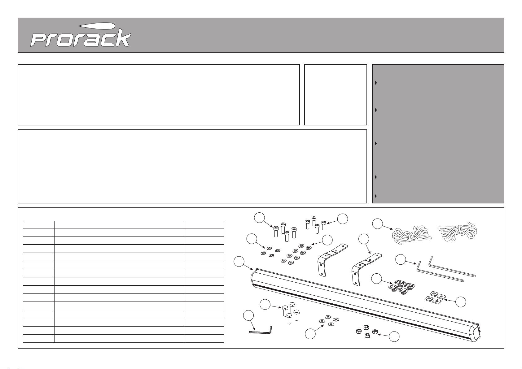
KIT CONTENTS
Item # Component Qty
1 Shade Awning 2 x 2m 1
2 Awning Bracket 2
3 Pegs 2
4 Guy Rope 2
5 M8 Spring Nut 4
6M8 T-Nut 4
7M8 Washer 8
8M8 Spring Washer 4
9 M8 Socket Head Capscrew 25mm 4
10 M8 Socket Head Capscrew 20mm 4
11 M6 Hex Bolt 4
12 M6 Washer 4
13 M6 Nylock Nut 4
14 6mm Allen Key 1
09-13-577 Rev 1
TOOLS REQUIRED
• Tape measure
• 10mm Spanner
• Torque Wrench
(optional)
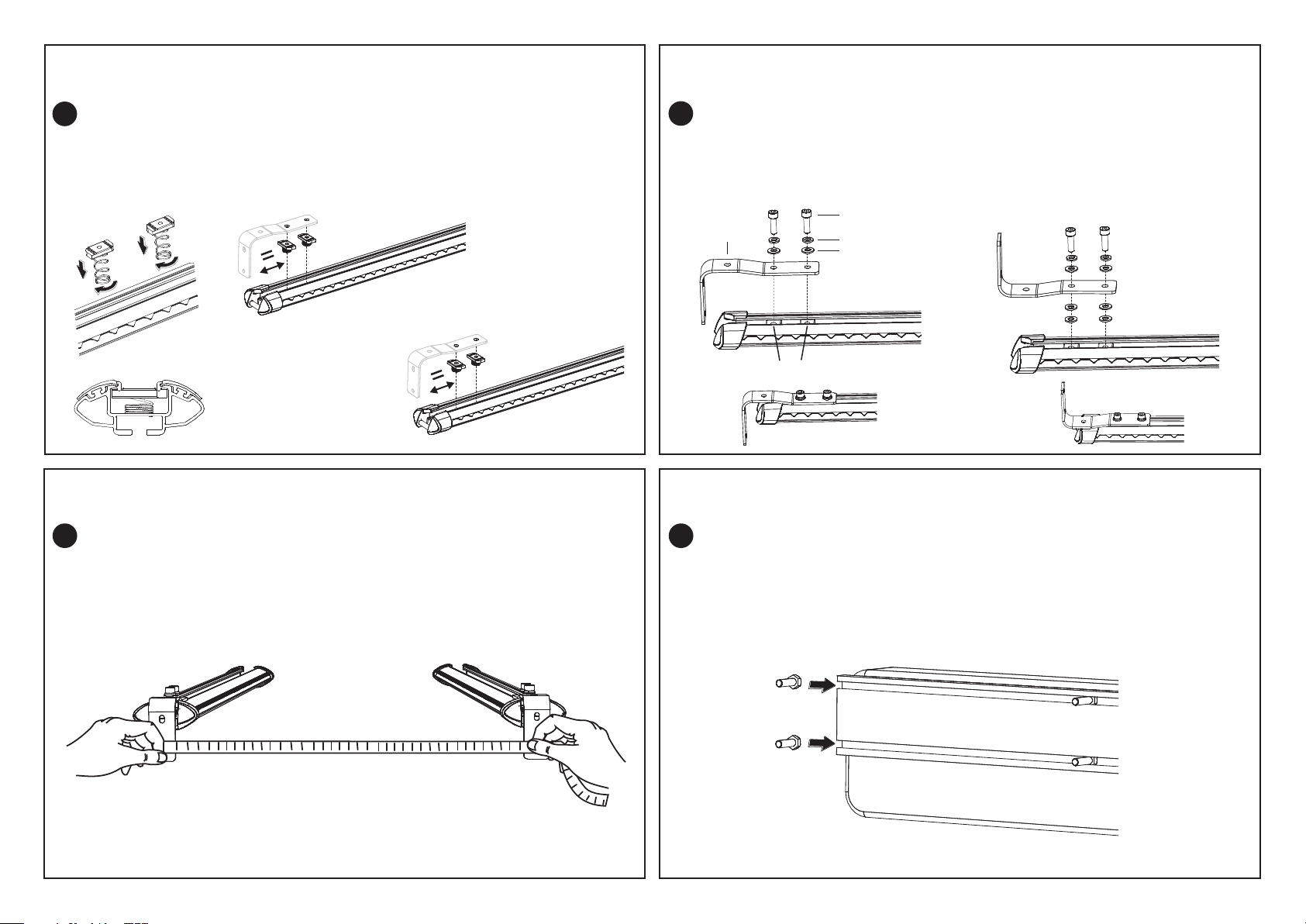
Installing Shade Awning direct to Prorack HD,
Tradesman and other Heavy Duty Crossbars
Go to Step 1
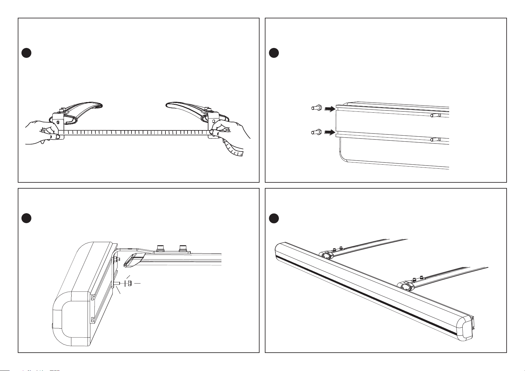
Installing Shade Awning direct to Prorack S-Wing
and International T-Slot Crossbars
Go to Step 7
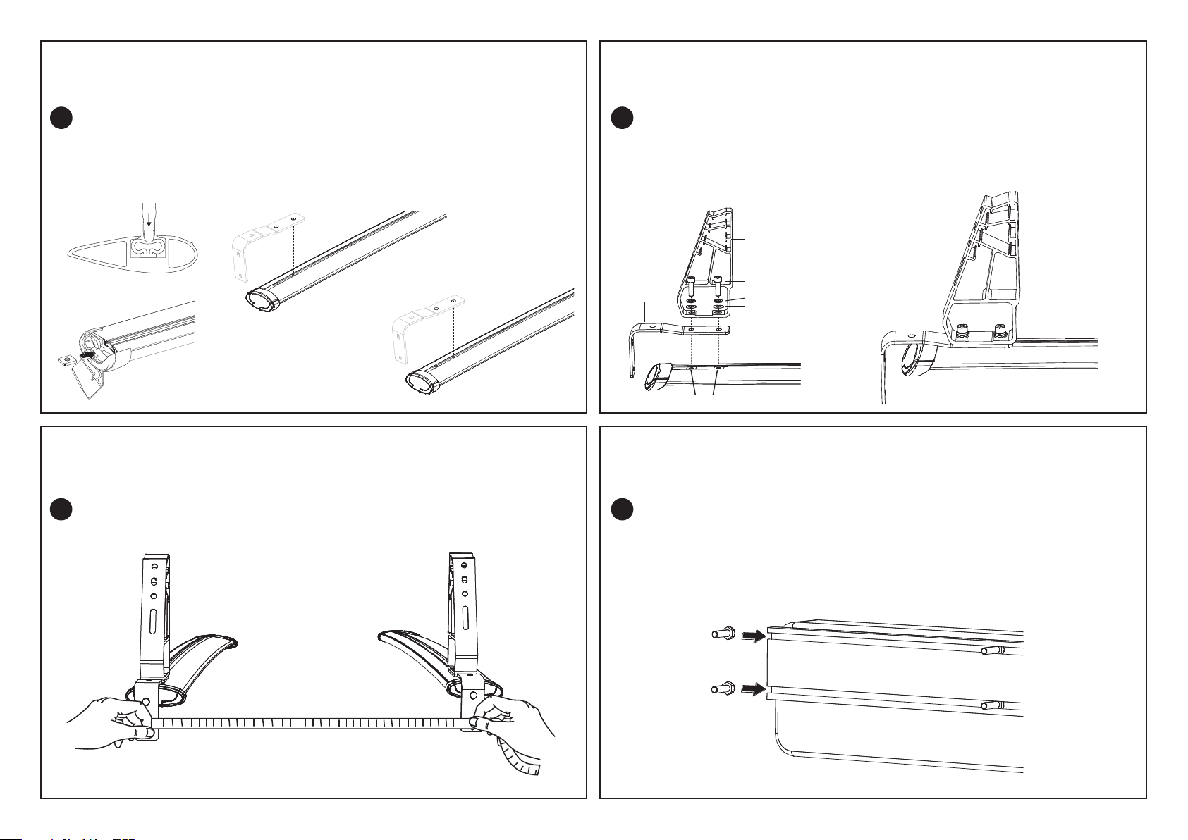
Installation of Shade Awning plus Recovery Tracks
Carrier Mounting Brackets (PR3207) on Prorack
HD, Tradesman and other Heavy Duty Crossbars
Go to Step 13
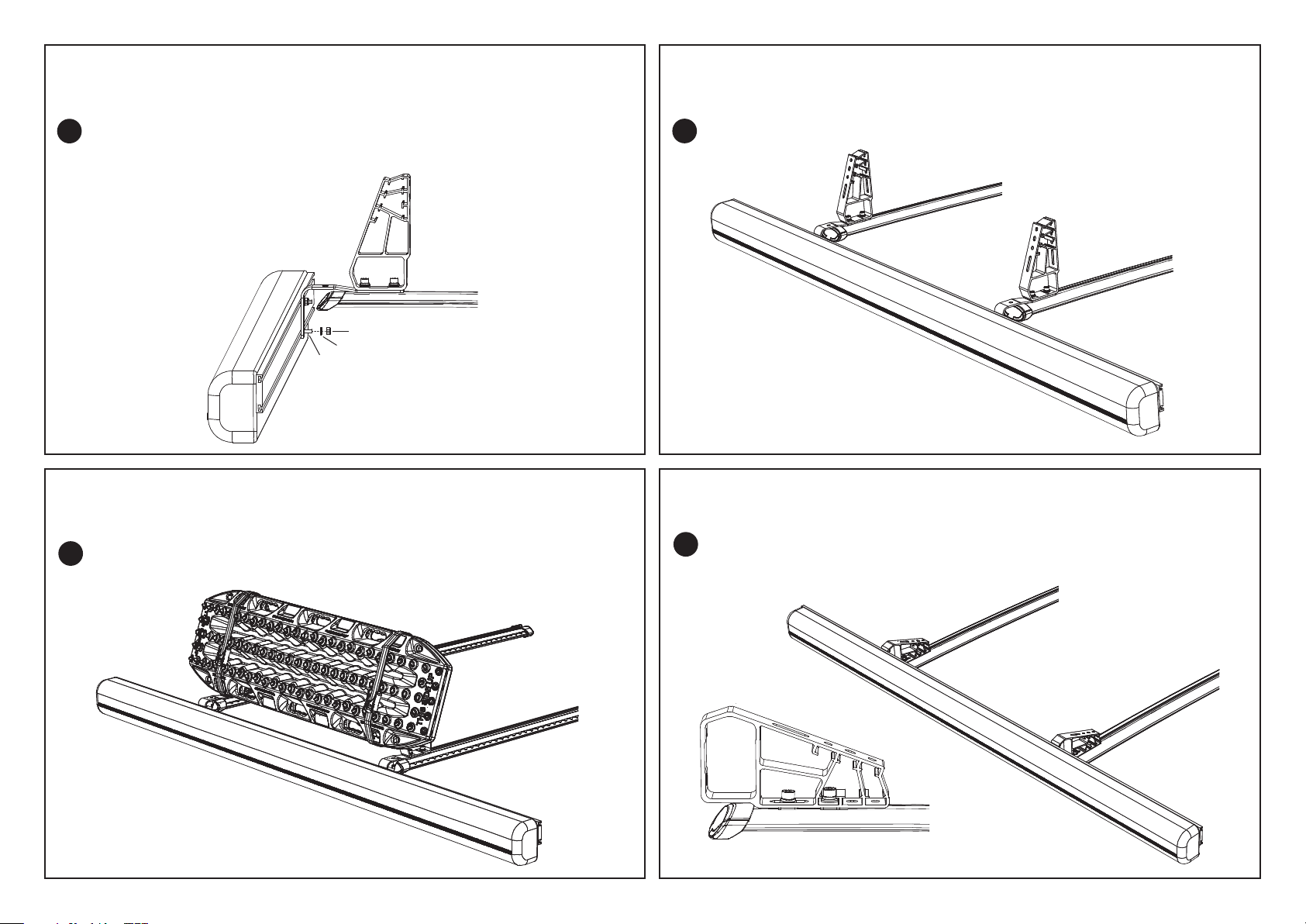
Installation of Shade Awning plus Recovery Tracks
Carrier Mounting Brackets (PR3207) on Prorack
S-Wing and International T-Slot Crossbars
Go to Step 21
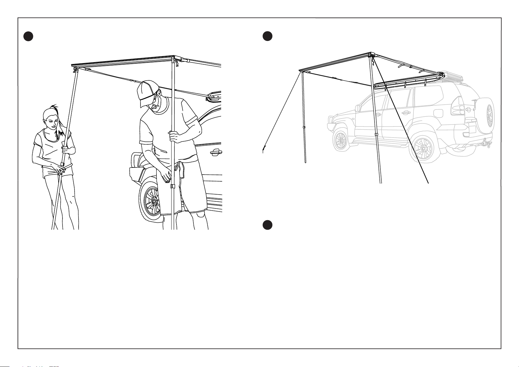
Set-up and Pack-up of Shade Awning
Go to page 9
1
2
3
4
5
6
7
8
11
12 13
910
14