Patton electronics 3002 User manual
Other Patton electronics Network Hardware manuals
Patton electronics
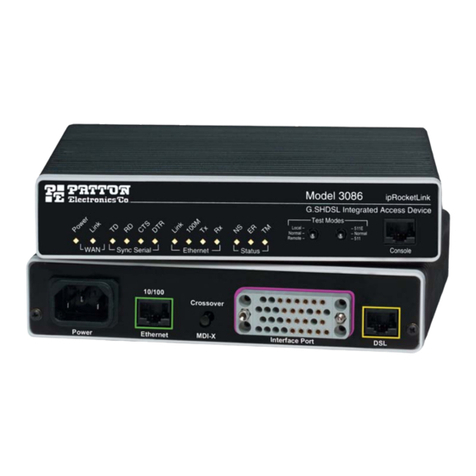
Patton electronics ipRocketLink IAD 3086 User manual
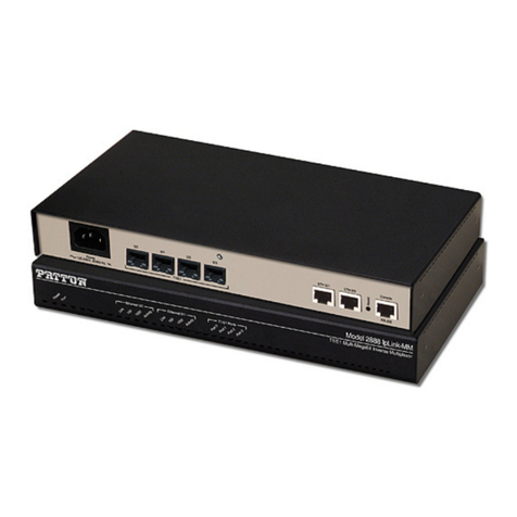
Patton electronics
Patton electronics 2888 Reference guide
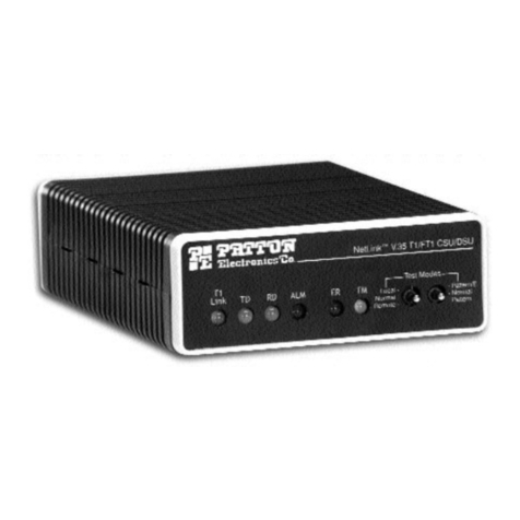
Patton electronics
Patton electronics NetLink 2720/B User manual
Patton electronics
Patton electronics SMARTNODE 4900 User manual
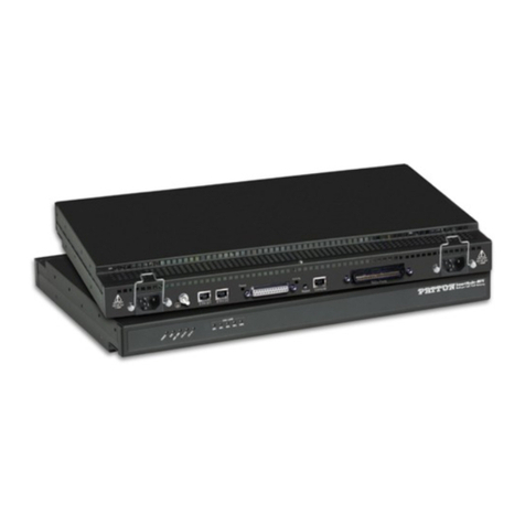
Patton electronics
Patton electronics SL402X User manual

Patton electronics
Patton electronics 2450 User manual
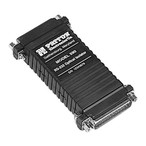
Patton electronics
Patton electronics 593/45 User manual

Patton electronics
Patton electronics 2025 User manual
Patton electronics
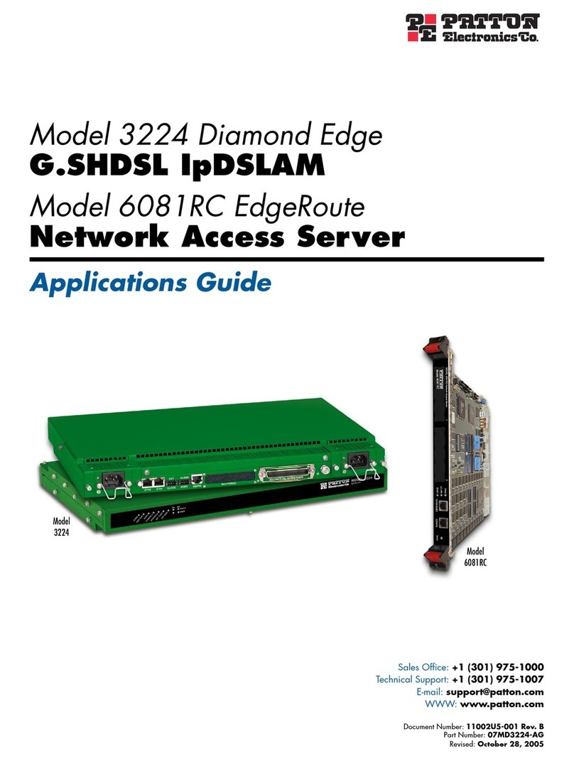
Patton electronics 2500 Series User manual
Patton electronics
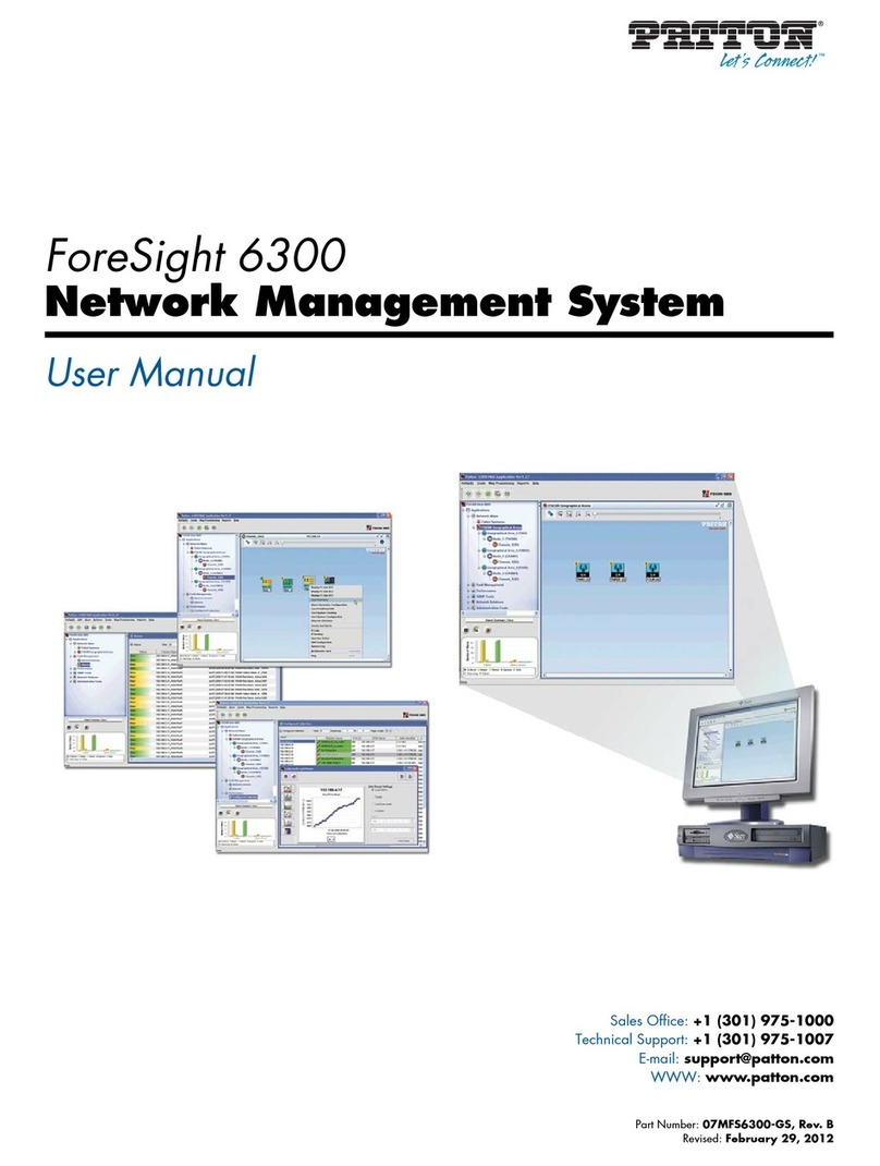
Patton electronics ForeFront 6081RC EdgeRoute User guide
Patton electronics
Patton electronics FORESIGHT 6300 User manual
Patton electronics
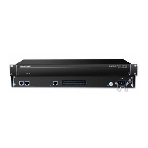
Patton electronics SmartNode 4400 User manual
Patton electronics
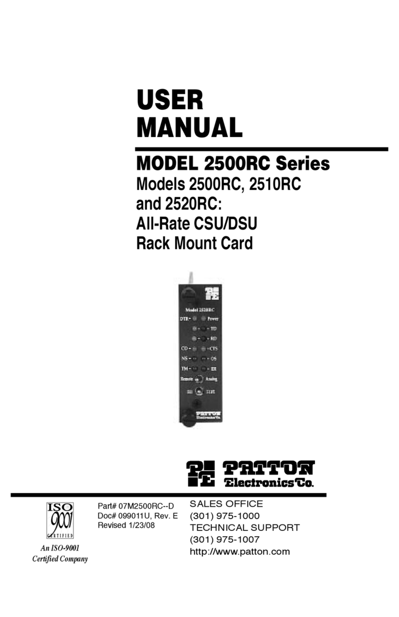
Patton electronics 2500RC User manual
Patton electronics
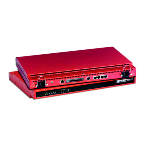
Patton electronics NetLink 2960 RAS User manual
Patton electronics
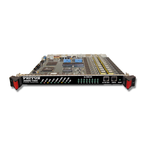
Patton electronics 3096RC User manual
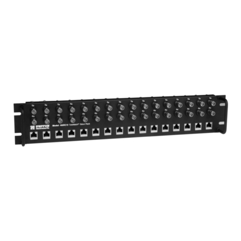
Patton electronics
Patton electronics 460RC User manual
Patton electronics
Patton electronics IM 1/F User manual
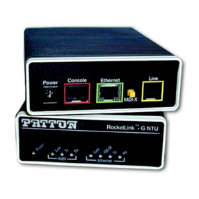
Patton electronics
Patton electronics RocketLink-G 3088/I User manual
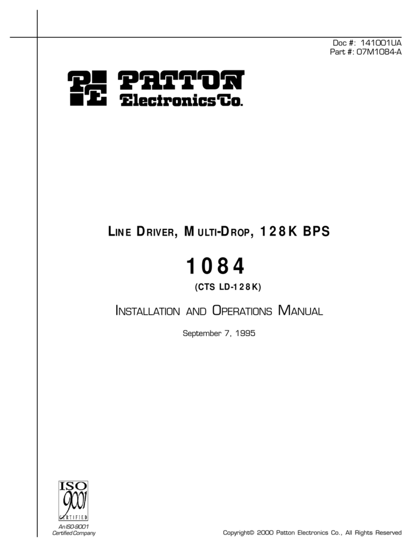
Patton electronics
Patton electronics 1084 User manual

Patton electronics
Patton electronics 3095 User manual
Popular Network Hardware manuals by other brands

Matrix Switch Corporation
Matrix Switch Corporation MSC-HD161DEL product manual

B&B Electronics
B&B Electronics ZXT9-IO-222R2 product manual

Yudor
Yudor YDS-16 user manual

D-Link
D-Link ShareCenter DNS-320L datasheet

Samsung
Samsung ES1642dc Hardware user manual

Honeywell Home
Honeywell Home LTEM-PV Installation and setup guide
