ProSeal GTR User manual

Serial No
:
GTR-3455
Doc Ref: Page: 1
Date: 13/01/13 Issue: H
Pr seal
®
uk
Tray Sealing Solutions
Operation and Maintenance Manual
GTR Rotary Table Heat Sealing Machine

Serial No
:
GTR-3455
Doc Ref: Page: 2
Date: 13/01/13 Issue: H
Pr seal
®
uk
Tray Sealing Solutions
AMENDMENT RECORDS
Issue
Author
Date Description of Change Background
A 10/05/07 First Issue
B AM 06/05/10 Declaration of Incorporation standards updated
C AM 26/11/10 Cleaning statement added
D AM 27/07/12 Supply of machinery document statement updated to
2008
E AM 27/07/12 Auto top tool clamp description added
F 13/01/13 Inverter error appendix added
G AM 9 May 13 Systems appendices added
H AM 26 Mar 14
Service schedule and fault finding updated
REVISION RECORDS
Revision Author Date Description of Change Background

Serial No
:
GTR-3455
Doc Ref: Page: 3
Date: 13/01/13 Issue: H
Pr seal
®
uk
Tray Sealing Solutions
CONTENTS
1. INTRODUCTION...................................................................................................................5
1.1 Materials................................................................................................................................5
1.2 Components..........................................................................................................................6
1.3 Important ...............................................................................................................................7
1.4 Scope....................................................................................................................................7
1.5 General Description...............................................................................................................7
1.6 Machine Footprint and Specifications ....................................................................................8
1.7 Technical specification...........................................................................................................9
1.8 Principle of Operation ..........................................................................................................10
1.9 GTR Control Panel ..............................................................................................................11
1.10 Machine safety and warning stickers ...................................................................................12
2. INSTALLATION ..................................................................................................................13
2.1 Foundations.........................................................................................................................13
2.2 Location...............................................................................................................................13
2.3 Lifting and Positioning..........................................................................................................13
2.4 Pneumatic Connection.........................................................................................................14
2.5 Gas Connection...................................................................................................................14
2.6 Electrical Connection...........................................................................................................14
2.7 Guarding..............................................................................................................................14
3. GTR MACHINE PRODUCTION RUNNING.........................................................................15
3.1 Start Up Procedure..............................................................................................................15
3.2 Emergency Shut Down Procedure.......................................................................................16
3.3 Film Feed Loading...............................................................................................................16
3.3.1 Registered Film Feed Loading............................................................................................18
3.3.2 Top Tool Auto Clamp (If Fitted)...........................................................................................19
3.3.3 Top Tool Auto Clamp Operation..........................................................................................19
3.4 GTR Tool Arrangement........................................................................................................20
3.5 GTR Production Settings.....................................................................................................21
3.5.1 Temperature Control...........................................................................................................21
3.5.2 Seal Dwell Time..................................................................................................................21
3.5.3 Film Feed Time...................................................................................................................21
3.5.4 Film Rewind Tension Settings.............................................................................................22
3.5.5 Gas Flush Time Settings.....................................................................................................22
3.5.6 Gas Flush Pressure Regulator Settings..............................................................................22
4. CLEANING OF YOUR PROSEAL MACHINE .....................................................................23
4.1 Machine Description............................................................................................................24
4.2 Control Cubicle....................................................................................................................25
4.2.1 Cleaning Instructions...........................................................................................................25
4.2.2 Control Cubicle Maintenance Checks .................................................................................25
4.3 GTR Control Panel ..............................................................................................................26
4.3.1 Control Panel Maintenance Checks....................................................................................26
4.4 Film Feed Assembly............................................................................................................27
4.4.1 Film Feed Maintenance Checks..........................................................................................27
4.5 Film Rewind Assembly.........................................................................................................28
4.5.1 Film Rewind Maintenance Checks......................................................................................28
4.6 Seal Station.........................................................................................................................29

Serial No
:
GTR-3455
Doc Ref: Page: 4
Date: 13/01/13 Issue: H
Pr seal
®
uk
Tray Sealing Solutions
4.6.1 Seal Station Maintenance Checks.......................................................................................29
4.7 Table and Frame .................................................................................................................30
4.7.1 Table and Frame Maintenance Checks...............................................................................30
5. FAULT DIAGNOSIS............................................................................................................32
6. ADJUSTMENT AND MAINTENANCE ................................................................................35
6.1 Safety..................................................................................................................................35
6.2 General Safety Considerations............................................................................................36
6.3 Routine Maintenance...........................................................................................................36
6.3.1 Pneumatics.........................................................................................................................36
6.4 High Oxygen Gas Flush (IF FITTED)...................................................................................37
6.4.1 Turntable Removal..............................................................................................................37
6.4.2 Tool Changing.....................................................................................................................38
6.5 Cam Positioning, Damper Replacement and Setting ...........................................................39
6.5.1 Cam Positioning..................................................................................................................39
6.5.2 Damper Replacement and Setting ......................................................................................39
6.6 Gas springs .........................................................................................................................40
6.7 Machine Maintenance Schedule..........................................................................................41
6.8 Tooling Maintenance ...........................................................................................................42
6.8.1 Daily Pre-Start Routine .......................................................................................................42
6.8.2 Weekly (Including Daily Tasks)...........................................................................................42
6.8.3 Monthly (Including Weekly Tasks).......................................................................................42
6.8.4 Quarterly (Including Monthly Tasks)....................................................................................42
7. CONFIGURATION ..............................................................................................................43
7.1 Important .............................................................................................................................43
7.2 Scope..................................................................................................................................43
7.3 Recommended Reading......................................................................................................43
7.4 Inverter settings...................................................................................................................44
7.4.1 Film Feed Inverter...............................................................................................................44
8. DECLARATION OF CONFORMITY....................................................................................45
9. APPENDICIES ....................................................................................................................47
9.1 Appendix A – Inverter Errors And Fault Finding...................................................................47
9.2 Appendix B – Systems Set-Up Documents..........................................................................51
9.2.1 To set up a Mitsubishi D700 inverter (Ref MAP009)............................................................51
9.2.2 Temperature Controllers (Ref MAP021)..............................................................................52
9.2.3 To set up a reg film sensor (Ref MAP011) ..........................................................................53
9.2.4 Phase Monitor Set-Up (If Fitted) (Ref MAP016) ..................................................................54
9.2.5 To Communicate with an FX PLC (Ref MAP001)................................................................55
9.2.6 To Set Up A Temperature Controller (Ref MAP021) ...........................................................60
9.3 Appendix C – Spares...........................................................................................................61
9.4 Appendix D – Circuit Diagram..............................................................................................62

Serial No
:
GTR-3455
Doc Ref: Page: 5
Date: 13/01/13 Issue: H
Pr seal
®
uk
Tray Sealing Solutions
1. INTRODUCTION
These are the original instructions and not a translation of the operation and maintenance of the
GTR machine.
This manual describes the Proseal standard GTR rotary table heat sealing system. The machine
automatically gas flushes the tray cavity whilst it cuts and seals coated reel fed film onto pre-formed
filled trays. The machine may also be supplied as a GTR-B version which is designed to seal pre-
formed board trays with pre-cut lids. In this mode the film feed and rewind assemblies will have
been removed.
The machine has been cleaned to a satisfactory engineering standard prior to dispatch. It is your
responsibility to ensure the machine is cleaned to the relevant food hygiene standard prior to
production.
All Proseal machines are designed and constructed using materials which are safe to use in the
food processing environment. Consideration has been given during the design of the machines to
reduce the risk of product spills and to ensure they can be cleaned easily and effectively.
Safety interlocked doors are provided enabling enclosed areas to be accessed for cleaning.
The operation of Proseal machines means they do not come into direct contact with food products
Components such as bearings; belts pneumatic and electrical components are industry standard
approved components for use in the food production environment.
Any lubricants used on the machine are foodsafe grades.
To ensure your Proseal machine remains hygienic, correct maintenance procedures should be
followed and any defective parts should be replaced
The correct cleaning of your Proseal machine is also vital.
1.1 Materials
Below is a list of materials used in the construction of a Proseal machine:
•5083 Anodised Aluminium
This material is widely used in the machine construction. The aluminium is anodised to minimise
corrosion when strong cleaning fluids are used in the cleaning of the machine.
•5083 Hard Anodised and PTFE Coated Aluminium
This material is used in areas where the part is subject to contact with moving parts of the machine
such a conveyor belt support plates.
•304 Stainless Steel
This material is used the construction of all the enclosures; conduits and guarding of the machine. It
is also widely used for components and structural parts of the machine.
•304 A2 Stainless Steel Fasteners
•All fasteners used on the machine are A2 (304) grade.
•Engineered Plastics
•Various plastic materials are used on Proseal machines such as Acetal; polyurethane; HDPE.

Serial No
:
GTR-3455
Doc Ref: Page: 6
Date: 13/01/13 Issue: H
Pr seal
®
uk
Tray Sealing Solutions
1.2 Components
All Proseal machines are constructed using components which are safe to use in the food
processing environment.
Below is a list of typical components used in the construction of a Proseal machine:
•Roller Bearings
All roller bearings are stainless steel specification. Some have plastic housings which are resistant
to corrosion and inert to cleaning agents.
•Polymer Bearings
Polymer bearings are also used in Proseal machines. They do not require any lubrication and have
good chemical resistance to diluted cleaning agents which may be used to clean the machine.
•Conveyor Belts
All conveyor belts used on Proseal machines are FDA approved and are of a hygienic design to
reduce the chance of product contamination.
•Electrical Components
All electrical components which are exposed to possible water ingress due to their location are
specified to a minimum IP65 rating. This ensures that they can be carefully cleaned by hand, in-
situ. Components in the working area of the machine may be protected by covers to reduce their
exposure water ingress during cleaning. All other components are located in sealed stainless steel
enclosures.
•Pneumatic Components
All pneumatic components pipes and fittings are industry standard which are designed to withstand
the normal wash down procedures associated with Proseal machinery.
Serial No
:
GTR-3455
Doc Ref: Page: 7
Date: 13/01/13 Issue: H
Pr seal
®
uk
Tray Sealing Solutions
1.3 Important
These are the original instructions and not a translation of the operation and maintenance of the
GTR machine.
Operation of the GTR should only be performed by suitably trained staff and on site engineers.
Incorrect operation or incorrect parameterisation can adversely affect the overall performance of
the machine.
1.4 Scope
This manual is intended to aid operators and on site engineers in the day to day running of the GTR
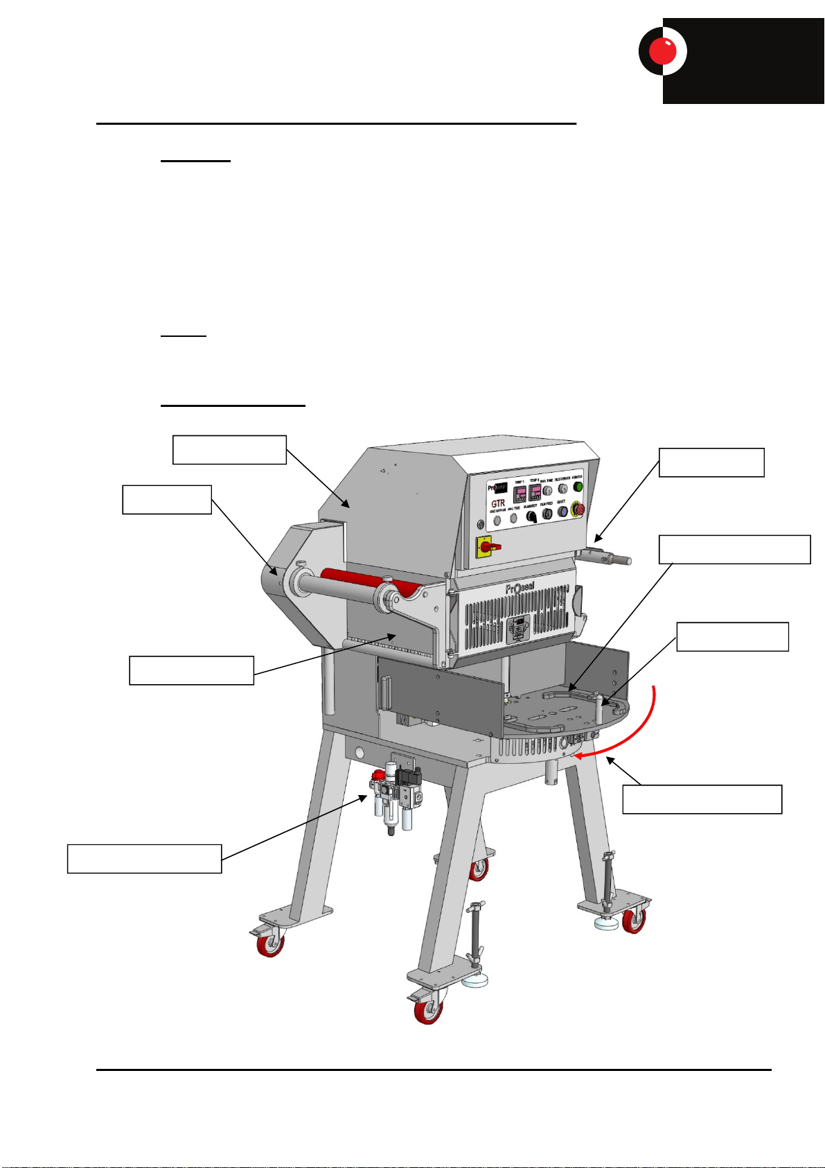
1.5 General Description
Film Rewind
Control Panel
Base Tool Location
Heat Seal Area
Table Handle
Air Preparation Unit
Film Feed
Direction of Rotation

Serial No
:
GTR-3455
Doc Ref: Page: 8
Date: 13/01/13 Issue: H
Pr seal
®
uk
Tray Sealing Solutions
1.6 Machine Footprint and Specifications
Weight 230 Kg
Production Speed 8-15 cycles per minute

Serial No
:
GTR-3455
Doc Ref: Page: 9
Date: 13/01/13 Issue: H
Pr seal
®
uk
Tray Sealing Solutions
1.7 Technical specification
Electrical Supply: 230 VAC 50 Hz
Electrical Supply Fuse Rating: 16 Amp anti-surge
208 VAC 60Hz (2 phase)
Electrical Supply Fuse Rating: 15 Amp anti-surge
Machine Power Rating: 3 Kw
Compressed Air Supply: 5.5-7 Bar
Compressed Air Consumption:
@ 50mm Stroke : 125 Bore Cylinder ≈97.7 nL/Min (3.5 CFM)
160 Bore Cylinder ≈162 nL/Min (5.7 CFM)
Compressed Air Input: 12mm
Machine Operating Temperature Range: 0°C to 40°C
Machine Operating Humidity Range: 35 – 85% RH Non-condensing
Airborne machine noise emissions: no greater than 70dB(A)
The machine is identified with a serial number plate. Always quote the serial number of the
machine when requesting information from Proseal as this will aid identifying the exact specification
of the machine.
This plate should not be removed from the machine

Serial No
:
GTR-3455
Doc Ref: Page: 10
Date: 13/01/13 Issue: H
Pr seal
®
uk
Tray Sealing Solutions
1.8 Principle of Operation
1. Filled trays are loaded into the base tool.
2. The table is manually rotated 180 degrees until the stop position is automatically made.
3. The sealing tool moves fully down applying heat to the coated film to seal it to the rim of the tray.
The cutting operation is incorporated into the sealing operation. The sealing tool is automatically
retracted after a pre-set time and the reel fed film is automatically fed on. If the machine is
configured to carry out gas flushing the seal cylinder is stopped in a predetermined position above
the base tool and gas is flushed into the trays. After a set time the gas valve is closed and the seal
tool moves fully down to seal and cut the film to the tray. The cycle is then the same as the
standard cycle.
4. The table is again manually rotated 180 degrees until the stop position is automatically made.
5. The sealed trays are raised out of the base tool for easy removal from the base tool.
Note:
Guards are fitted front and back of the machine to allow access to the sealing tool. If either of the
guards is opened the machine will stop instantly. A further switch and isolation solenoid valve are
fitted to isolate air supply to the seal cylinder down when table is not in station.
Always check the machine prior to commencement of operation for any non-conformance.
Always Report and log any defects, damage, malfunctions or misalignments found whilst operating
the Proseal GTR machine. Report all matters to the supervisor immediately, no matter how minor
they appear to be.
Do not carry out any operation unless you have read and understood the operating instructions
contained in this document.
Never operate the Proseal GTR machine, with any personnel inside the guarded area.
If in doubt, ASK the supervisor in charge.

Serial No
:
GTR-3455
Doc Ref: Page: 11
Date: 13/01/13 Issue: H
Pr seal
®
uk
Tray Sealing Solutions
1.9 GTR Control Panel
The following operator interfaces are provided to allow quick and simple operation of the GTR
Button Function
Reset Used to reset the emergency stop circuit.
Emergency Stop Used in the event of an emergency where immediate stopping of the machine is
required. When pressed the safety circuit becomes de-energised and power is
removed from the air supply dump valve and head down isolation valve.
Guard Lamp Guard circuit ok indication, illuminated when ok.
Seal
Temperature Adjustable temperature controller for the sealing tool.
Manual Film
Feed A Black button to feed the film on manually.
Seal Timer Adjustable timer controlling the amount of time the sealing head stays in the
down position.
Film Feed Timer Adjustable film feed timer, which controls the length of film during automatic
operation.
Plain /
Registration A plain / registration switch is fitted to the machine enabling the operator to
switch from plain film to printed film.
Gas Off / On
(Optional) A Gas Off / On switch is fitted to the machine enabling the operator to switch
from atmospheric sealed trays to gas flushed sealed trays.
Gas Time
(Optional) Adjustable timer controlling the amount of time gas is flushed into the tray prior
to completion of the sealing operation.
Mains Isolator
Switch Electrically isolates the machine. Switch to 1 to supply power and 0 to isolate
the power supply.
Note: The machine may be supplied with a 3 position gas selector switch to include
gas flushing of board lids (“Gas Knife” option).

Serial No
:
GTR-3455
Doc Ref: Page: 12
Date: 13/01/13 Issue: H
Pr seal
®
uk
Tray Sealing Solutions
1.10 Machine safety and warning stickers
Below is a list of warning sign which may be fitted to the machine
PICTOGRAM DESCRIPTION PICTOGRAM DESCRIPTION
Warning sign
indicating a potential
crush hazard
between gears or
sprockets and chain.
Safety sign to signify
that protective
gloves must be worn
Warning sign
indicating a potential
crush hazard
between machine
parts
Safety sign to
indicate an electrical
hazard in such as in
an enclosure or an
electrical switch.
Warning sign
indicating a potential
burn hazard from hot
parts on the machine
Prohibition sign to
warn operators not
to reach into the
area indicated
Warning hazard
indicating that the
tooling in the
machine is heavy
and requires a multi-
person lift with the
correct procedures
being observed.
Warning sign
indicating there is a
laser hazard present
Danger Crush
garder les mains
éloignées
Heavy load:
Multi-person lift
required
ST5018 Multi-person Lift
Protective gloves
must be worn
Do not
reach in
Avoid direct and
scattered contact
to Skin & Eyes
Serial No
:
GTR-3455
Doc Ref: Page: 13
Date: 13/01/13 Issue: H
Pr seal
®
uk
Tray Sealing Solutions
2. INSTALLATION
2.1 Foundations
The foundation surface should be level, flat, and of sufficient strength and thickness to support the
weight of the machine.
2.2 Location
The machine should be located in a position that is free from draughts, from adjacent doors or
windows, which could adversely affect the sealing operation. The machine should be positioned
such that it does not cause a health and safety hazard due to its location.
Reasonable access must be left around all the sides of the machine for the changeover of sealing
tools and film reels.
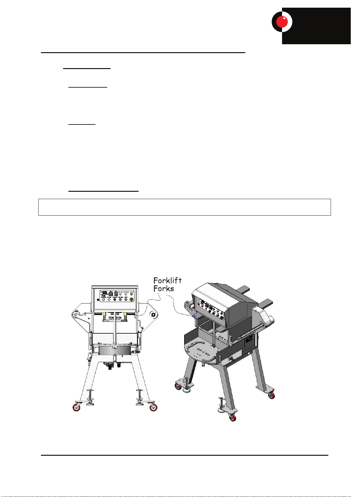
2.3 Lifting and Positioning
WARNING: -
Always use suitably tested lifting gear with adequate lifting capacity for the weight of the machine.
Care must be taken, at the time of installation and during any subsequent removal, not to damage
or distort the turntable. The machine may be adjusted for height or for levelling using the adjustable
feet fitted.
When using forklift trucks, open front and rear doors, locate the forks with the forks spread wide
enough to clear guide rods as per diagram. Take care not to hit or damage any of the electrical
connections or guard switches. Please see drawing below for correct positioning.
Ensure the vehicle has adequate lifting capacity, and is fitted with suitable length forks or
extensions to support the machine.

Serial No
:
GTR-3455
Doc Ref: Page: 14
Date: 13/01/13 Issue: H
Pr seal
®
uk
Tray Sealing Solutions
2.4 Pneumatic Connection
The machine requires a compressed air supply of 5-6 Bar, which should be connected to the inlet
port of the air service set situated on the side of the machine.
2.5 Gas Connection
When the machine is operating in gas flush mode the modified atmosphere packaging gas should
be connected to the inlet port situated under the machine frame. Adjust the GTR pressure regulator
to give a gauge reading of 1 to 1.5 Bar. The gas pressure is monitored via a pressure switch. If the
value falls below a set level the guard lamp will flash and a beep sound will be heard.
2.6 Electrical Connection
The machine must be electrically connected as indicated in the machine Electrical Wiring Diagram
(Appendix A) and sized to match the requirements outlined in the Technical Specifications (Section
8).
2.7 Guarding
There is a legal obligation upon the installer to ensure the machine is in safe condition before
attempting to run.
The guard circuit is a dual channel monitoring circuit and complies with a category 3-guard circuit.
WARNING: -
On no account must Proseal machines be operated without the guarding supplied, or with any
safety device or circuit disabled or bypassed.
Before commencing operation, ensure all guarding is correctly fitted, and all guard safety interlock
switches and emergency stop switches are inspected and checked for correct operation.
All guard switches are secured using anti-tamper fasteners. Only competent qualified engineering
personnel should remove and replace guard switches using the correct tool.

Serial No
:
GTR-3455
Doc Ref: Page: 15
Date: 13/01/13 Issue: H
Pr seal
®
uk
Tray Sealing Solutions
3. GTR MACHINE PRODUCTION RUNNING
WARNING: -
1. Nothing in these instructions should be assumed to supersede any operating or safety
procedures applicable at your own place of work.
2. Technically unqualified personnel should not attempt to open the control panel door or make any
unauthorised machine adjustments.
3.1 Start Up Procedure
WARNING: -
1. Before you start the machine ENSURE YOU KNOW HOW TO STOP IT!
2. Note the position of the emergency stop.
3. Opening the guard doors will also stop the machine in an emergency.
4. Take notice of all warning signs, including machine nip points and precautions during machine
operations.
1. Ensure the turntable is "clear" of any foreign objects, and that matching top tool and base tools
are fitted.
CAUTION: -
The machine must only be run with the correct top tool and matching base tool to avoid the cutting
blades, on a mismatched tool set, clashing with the base tool.
2. Switch mains isolator to the on “1” position.
NOTE: -
This puts power onto the heaters and should be switched on approximately 20 minutes before
production to ensure the correct tool temperature is reached.
3. Check the compressed air supply is switched on.
The air gauge on air supply set should read 5 to 6 Bar
4. Load film into the machine (as per instructions in section 3.4)
5. Ensure the seal, film feed and gas timers are set at the desired levels.
6. Place a product filled tray in the base tool.
7. Close all guards and press RESET to reset guard circuit.
8. Rotate table 180 degrees.
9. Sealed trays are raised for removal. Remove and replace with new trays.
10. Rotate table 180 degrees to repeat the operation and carry on with production.

Serial No
:
GTR-3455
Doc Ref: Page: 16
Date: 13/01/13 Issue: H
Pr seal
®
uk
Tray Sealing Solutions
3.2 Emergency Shut Down Procedure
The machine can be stopped instantly by depressing the EMERGENCY STOP button (or by
opening a guard door). The air supply will be isolated whilst any residual compressed air in the
system will be dumped causing the sealing tool to retract. Power to the control panel will be
isolated.
To restart the machine, ensure the front and back guards are closed and the emergency
stop button is not depressed, then press the RESET button.
3.3 Film Feed Loading
The GTR machine is fitted with a simple inverter driven film feed mechanism. The film will accept
a maximum of Ø250mm reel, with a maximum of 330mm width. (Note: wider film up to 350mm
can be accommodated. Consult Proseal for advice). The size of the core is irrelevant to the GTR
machine.
To load the film, carry out the following steps.
1. Break the seal on the reel of film.
2. Place the reel on top of the driven rollers 1 + 2
3. Align the film roll centrally on the driven rollers.
4. Move the reel collars in leaving approximately 1mm either side of the reel and tighten
the thumb screws.
5. Press the manual feed button until approximately 1.5m is fed out.
Reel Collar
Driven Rollers 1 & 2

Serial No
:
GTR-3455
Doc Ref: Page: 17
Date: 13/01/13 Issue: H
Pr seal
®
uk
Tray Sealing Solutions
6. Follow the film path as shown in the film feed diagram.
7. Ensure the waste release knob is pushed in and rotated to its locked position.
8. Wrap excess film around the rewind shaft.
8. Press the manual film feed button to feed more film and ensure it is tight on the rewind shaft.
9. Check the film runs true and central to the sealing head.
10. The machine is now ready for production.
Rewind ShaftRelease Knob

Serial No
:
GTR-3455
Doc Ref: Page: 18
Date: 13/01/13 Issue: H
Pr seal
®
uk
Tray Sealing Solutions
To remove the excess film from the rewind shaft, snap the film at the rewind end. Twist the
film release knob and allow to pop out, releasing the tension from the waste film. Slide the
waste film easily off the rewind shaft.
3.3.1 Registered Film Feed Loading
If the GTR machine is fitted with a registered film mechanism, the following film feed path
should be used:
Serial No
:
GTR-3455
Doc Ref: Page: 19
Date: 13/01/13 Issue: H
Pr seal
®
uk
Tray Sealing Solutions
3.3.2 Top Tool Auto Clamp (If Fitted)
The GTR may be fitted with an optional top tool auto clamp facility. This set-up allows for the
clamping and electrical connection of the top tool via a single switch on the control panel. The tool
clamp will only function when all the guards are closed the table is locked in station and the safety
relay has been reset. Once the tool lock is operated the lift bars are raised and held in position by
compact cylinders.
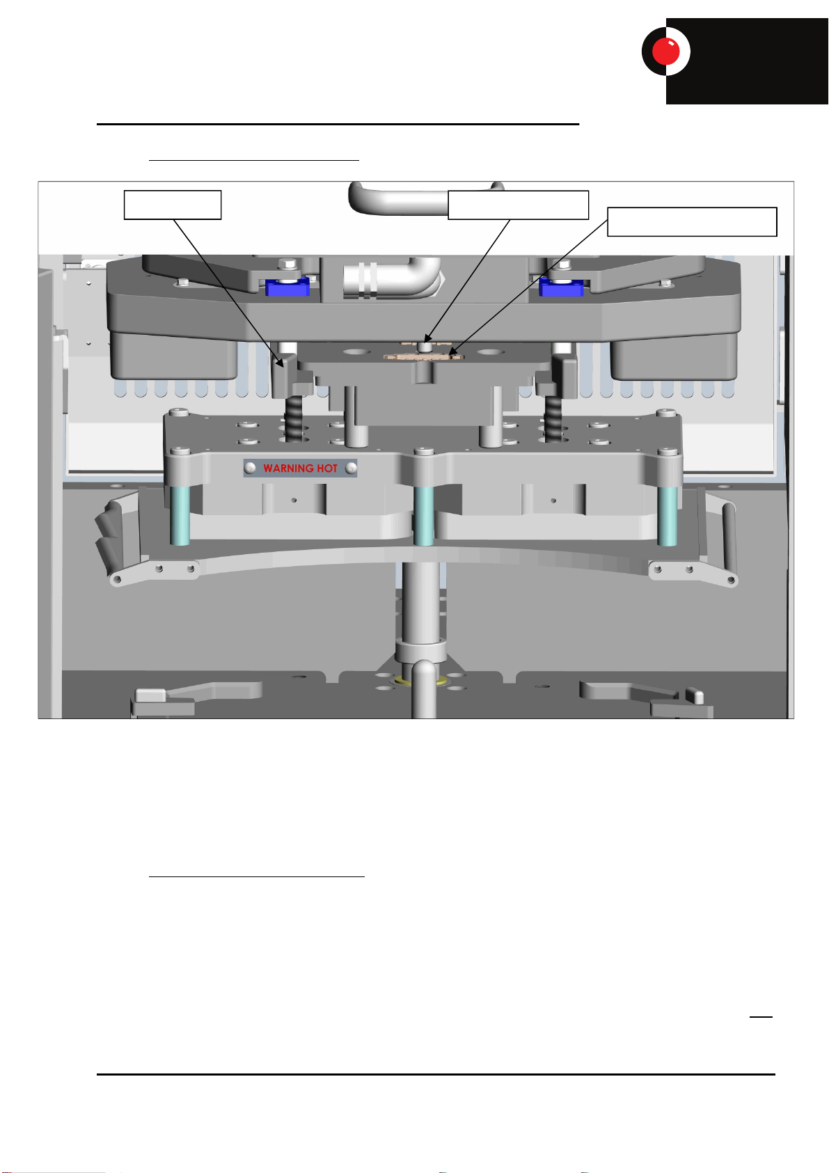
3.3.3 Top Tool Auto Clamp Operation
The tool lock will not operate until the table is in station, the guards are closed and the safety relay
reset. N.B. the machine requires air and mains power to be on at this point.
To lock/unlock the tool, operate the switch on the control panel.
If the tool is unlocked and the guards are closed and safety relay reset, the reset button will flash, to
give indication that the tool is not locked. The operation of the machine is disabled until the tool is
locked, including table rotation, seal head and film feed. The film rewind operates all the time the
safety relay is reset. If the tool lock is switched off when the safety relay is reset and the table is not
in station, the tool will remain locked until the table is rotated into station, at which point the tool will
unlock disabling the operation of the machine.
Electrical connections
Orientation dowelTool lift bar
Serial No
:
GTR-3455
Doc Ref: Page: 20
Date: 13/01/13 Issue: H
Pr seal
®
uk
Tray Sealing Solutions
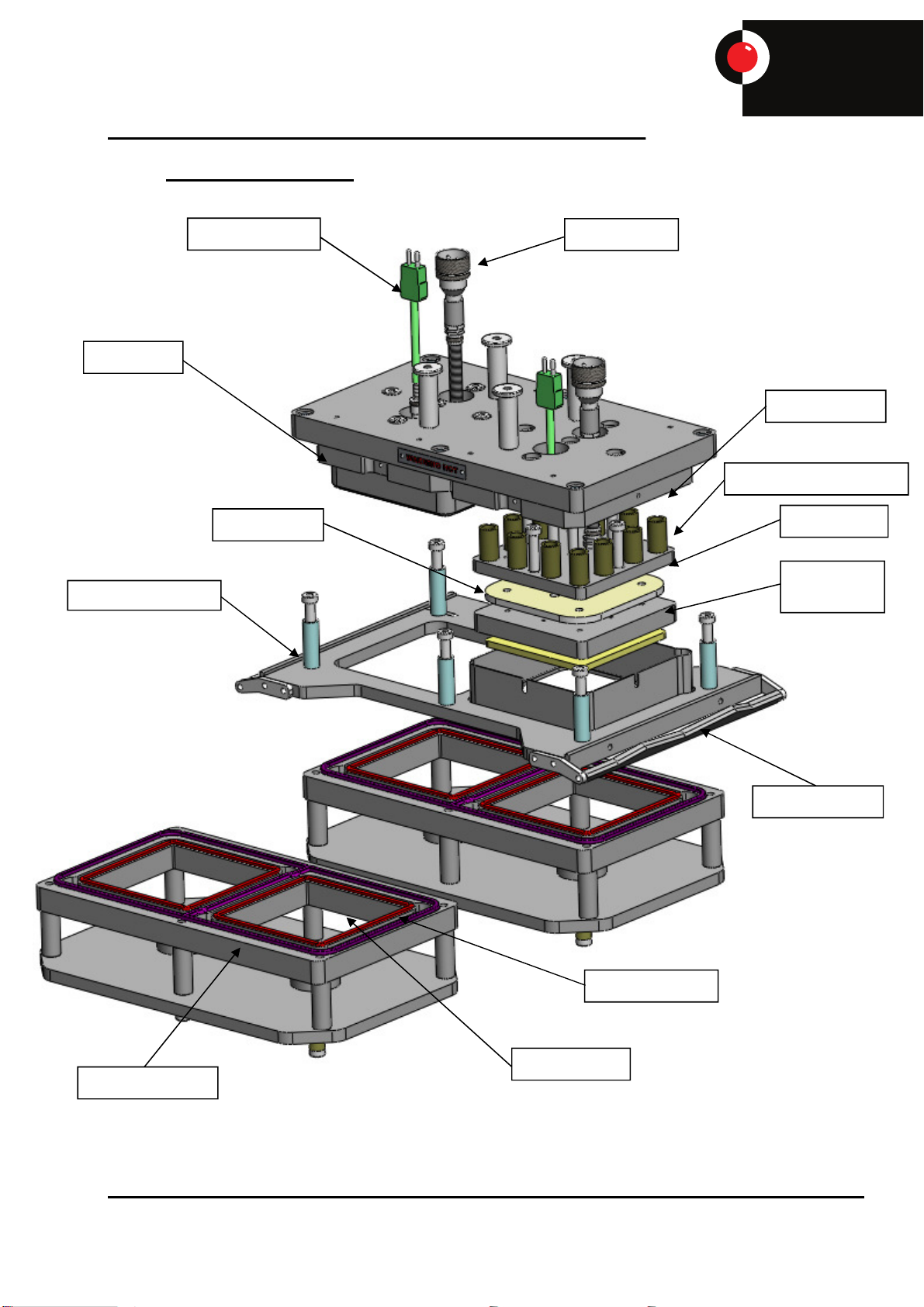
3.4 GTR Tool Arrangement
Heater Plug
PEEK Pad
(Optional)
Thermocouple
Heater Mat
Seal Springs
Element Clamp Plate
Clamp Rubber
Seal Rubber
Base Top Plate
Film Clamp Plate
Film Spreader
Trimblade
Seal Profile
Table of contents
Popular Industrial Equipment manuals by other brands

SCHUNK
SCHUNK VERO-S NSE-HT mini 88-20 Assembly and operating manual

Rexnord
Rexnord Falk NRTH B 1055 Installation & maintenance

Siemens
Siemens SIPROTEC 5 manual

Magnum Industrial
Magnum Industrial MI-12553 operating manual

Hoffmann
Hoffmann MORSO NFXL operating manual

Reflex
Reflex Servitec Installation, operating and maintenance instructions


