Cascade E Series User manual

Cascade is a Registered Trademark of Cascade Corporation
cascadeT
Manual Number 221093
ERVICE MANUAL
E-Series
Revolving Clamps
S

ONTENTS
C
i
Page
INTRODUCTION, Section 1
Introduction, 1.1 1
Special Definitions, 1.2 1
INSTALLATION, Section 2
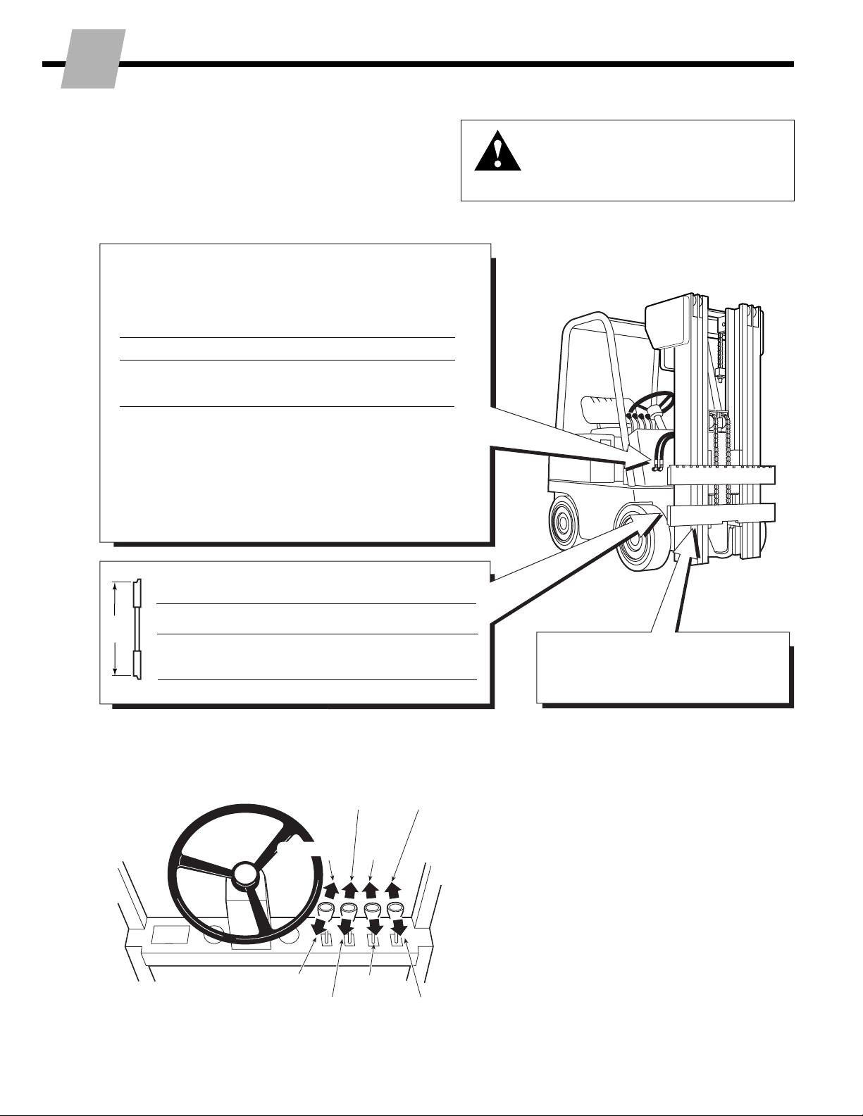
Truck System Requirements, 2.1 2
Recommended Hydraulic Supply Options, 2.2 3
Revolving Clamp Installation Procedure, 2.3 4
PERIOD MAINTENANCE, Section 3
100-Hour Maintenance, 3.1 10
500-Hour Maintenance, 3.2 10
1000-Hour Maintenance, 3.3 10
TROUBLESHOOTING, Section 4
General Procedures, 4.1 11
Truck System Requirements, 4.1-1 11
Tools Required (metric), 4.1-2 11
Troubleshooting Chart, 4.1-3 11
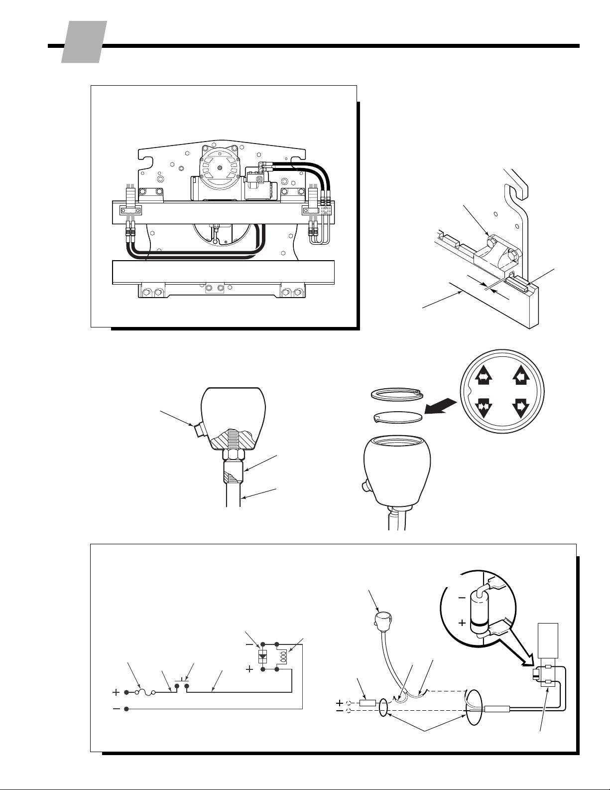
Plumbing, 4.2 12
Hosing Diagram, 4.2-1 12
Hydraulic Circuit, 4.2-2 13
Clamp Function, 4.3 14
Supply Circuit Test, 4.3-1 14
Clamp Circuit Test, 4.3-2 14
Rotate Function, 4.4 15
Supply Circuit Test, 4.4-1 15
Rotate Circuit Test, 4.4-2 16
Electrical Circuit, 4.5 17
SERVICE, Section 5
Revolving Clamp Removal, 5.1 18
Arms, 5.2 19
Arm Assemblies – Removal and Installation, 5.2-1 19
Drum Arm Pad Surface Replacement, 5.2-2 20
Rigid Arm Pad Replacement/Rotation, 5.2-3 21
Clamps without Arms, 5.2-4 22
Arm Bearings – Removal and Installation, 5.2-5 23
Drive Group, 5.3 24
Drive Group Removal and Installation, 5.3-1 24
Drive Group Disassembly and Service, 5.3-2 24
Drive Group Reassembly, 5.3-3 26
Drive Motor, 5.4 28
Drive Motor Removal and Installation, 5.4-1 28
Drive Motor Disassembly, 5.4-2 29
Drive Motor Inspection, 5.4-3 30
Drive Motor Reassembly, 5.4-4 30
Drive Check Valve, 5.5 32
Check Valve Service, 5.5-1 32
Revolving Connection/Manifold, 5.6 33
Rev.Conn. Removal and Installation, 5.6-1 33
Manifold Removal and Installation, 5.6-2 33
Rev.Conn. Service, 5.6-3 35
Relief Valve Adjustment, 5.6-4 37
Cylinders, 5.7 38
Cylinder Service, 5.7-1 38
Cylinder Disassembly, 5.7-2 38
Cylinder Inspection, 5.7-3 39
Cylinder Reassembly, 5.7-4 40
Cylinder Replacement, 5.7-5 42
Base Unit, 5.8 43
Rotation Bearing Removal and Installation, 5.8-1 43
180-Degree Stop Group, 5.9 45
Stop Valve Adjustment, 5.9-1 45
Stop Valve Service, 5.9-2 46
Solenoid Valve, 5.10 46
Coil Service, 5.10-1 46
Valve Service, 5.10-2 46
SPECIFICATIONS, Section 6
Specifications, 6.1 47
Hydraulics, 6.1-1 47
Auxiliary Valve Functions, 6.1-2 47
Truck Carriage, 6.1-3 47
Torque Values, 6.1-4 48
Page

221093 Rev. 0 1
NSTALLATION
I
1.1 Introduction
This Manual provides the Installation, Periodic Mainte-
nance, Troubleshooting, Service and Specifications for
Cascade E-Series Revolving Clamps.
E-Series Clamps are designed for three-shift-a-day
continuous-duty operations with minimal maintenance.
They offer exceptional visibility for the lift truck driver and
provide optimized clamp force and load handling.
In any communication about the Clamp, refer to the
product I.D. number stamped on the nameplate as shown.
If the nameplate is missing, the numbers can be found
stamped on the back of the baseplate.
IMPORTANT: All hoses, tubes and fittings on E-Series
Clamps are JIC.
NOTE: Specifications are shown
in both U.S. and (Metric) units.
1.2 Special Definitions
The statements shown appear throughout this Manual
where special emphasis is required. Read all WARNINGS
and CAUTIONS before proceeding with any work.
Statements labeled IMPORTANT and NOTE are provided
as additional information of special significance or to
make the job easier.
CAUTION - A statement preceded by CAUTION is
information that should be acted upon to prevent
machine damage.
IMPORTANT - A statement preceded by IMPORTANT is
information that possesses special significance.
NOTE - A statement preceded by NOTE is information
that is handy to know and may make the job easier.
WARNING - A statement preceded by
WARNING is information that should be
acted upon to prevent bodily injury. A
WARNING is always inside a ruled box.
I
NTRODUCTION
33E-MR-00001
cascade
LIFT TRUCK ATTACHMENT
ATTACHMENT CAPACITY
SERIAL
NUMBER
CATALOG
NUMBER
ADDITIONAL
EQUIPMENT
ADDITIONAL
EQUIPMENT
ADDITIONAL
EQUIPMENT
FOR TECHNICAL ASSISTANCE, PARTS AND SERVICE
CONTACT:
1-800-227–2233
PORTLAND, OREGON USA
WEIGHT
LBS.
POUNDS
AT INCH LOAD
CENTER
CAPACITY OF TRUCK AND ATTACHMENT COMBINATION
MAY BE LESS THAN ATTACHMENT CAPACITY SHOWN
ABOVE. CONSULT TRUCK NAMEPLATE.
RECOMMENDED SYSTEM PRESSURE – 2000 PSI
MAXIMUM SYSTEM PRESSURE – 2300 PSI
cascade
T
T
c
S/N 33E-MR-00001
CL0792.ill
Nameplate

2 221093 Rev. 0
NSTALLATION
I
GA0082.ill
GA0080.ill
Clamp
Rotate
CW
Tilt
Forward
Hoist Up
WARNING: Rated capacity of the truck/
attachment combination is a responsibility
of the original truck manufacturer and may
be less than that shown on the attachment
nameplate. Consult the truck nameplate.
Carriage
Clean carriage bars and inspect for
damaged notches
Tilt
Back
Hoist Down
Release
Rotate
CCW
GA0028.ill
Carriage Mount Dimension (A) ITA (ISO)
Minimum Maximum
Class II 14.94 in. (380.0 mm) 15.00 in. (381.0 mm)
Class III 18.68 in. (474.5 mm) 18.74 in. (476.0 mm)
Truck Relief Setting
2300 psi (160 bar) Recommended
2600 psi (180 bar) Maximum
Truck Flow Volume ➀
Min. ➁Recommended Max. ➂
30E, 33E, 5 GPM 7.5 GPM 10 GPM
40E, 45E (19 L/min.) (28 L/min.) (38 L/min.)
➀Cascade E-Series Revolving Clamps are compatible with SAE 10W
petroleum base hydraulic fluid meeting Mil. Spec. MIL-0-5606 or
MIL-0-2104B. Use of synthetic or aqueous base hydraulic fluid is
not recommended. If fire resistant hydraulic fluid is required,
special seals must be used. Contact Cascade.
➁Flow less than recommended will result in a rotate speed of less
than 2 RPM and possible unequal arm movement.
➂Flow greater than maximum can result in excessive heating,
reduced system performance and reduced hydraulic system life.
A
2.1 Truck System
Requirements
E-Series Revolving Clamps will provide maximum operat-
ing capability when the following requirements are met.
Auxiliary Valve Functions
Check for compliance with
ITA (ISO) standards:

221093 Rev. 0 3
NSTALLATION
I
A and B
RH and LH THINLINE™2-port hose reel groups.
OR
A
Solenoid Adaption using RH 6-N-1 Cable/Hose Reel
Group
OR
A and C
RH THINLINE™2-Port Hose Reel Group for ROTATE
function, and Mast Single Internal Hose Reeving Group
for CLAMP function.
B
A
GA0033.ill
C
2.2 Recommended
Hydraulic Supply
Options
E-Series Revolving Clamps can be operated with any of
the hydraulic supply arrangements shown below. Refer to
Cascade Hose & Cable Reel Selection Guide, Part No.
212199, to select the correct hose reel for the mast and
truck. The hose and fitting requirements are:
• Hoses and fittings for the CLAMP function should be
No. 6 with 9/32 in. (7 mm) minimum I.D.
• Hoses and fittings for the ROTATE function should be
No. 8 with 13/32 in. (10 mm) minimum I.D.

4 221093 Rev. 0
NSTALLATION
I
Follow the steps shown to install the Revolving Clamp on the truck.
Read and understand all WARNING and CAUTION statements. If
you don't understand a procedure, ask your supervisor, or call the
nearest Cascade Service Department for assistance.
2Unlock Quick-Change lower
mounting hooks
AMove hooks into unlocked position.
BReinstall pin in lower hole.
1
Tighten Capscrews:
Class II / III Mounting – 165 ft.-lbs. (225 Nm)
cascade
®
C-675514-1
CL0097.ill
A
Pin
LH lower
Hook
NOTE: Guides can be reversed to
reduce hook-to-carriage clearance
(See Step 7).
5/8-in. (16 mm)
offset on top
provides max.
clearance.
Guide
WARNING: Make sure overhead
hoist has rated capacity of at least
3500 lbs. (1600 kg).
B
CL0333.ill
A
B
A
Attach overhead hoist
ARemove banding, set Revolving
Clamp upright on pallet. Use
lifting eyes and multiple chains to
stabilize Clamp while lifting.
BRemove bolt-on lower mounting
hooks (if equipped).
Lifting
Eye
Lower
Hooks
2.3 Installation Procedure

221093 Rev. 0 5
NSTALLATION
I
CL0334.ill
CLAMP
OPEN
Prepare Hoses
ADetermine hose lengths required for hydrau-
lic supply configuration of truck.
BCut hoses to length, install end fittings.
3
Flush hydraulic supply hoses
AInstall hoses as shown.
BOperate auxiliary valves for 30 sec.
CRemove union fittings, hoses.
DConnect hoses to Revolving Clamp
fittings as shown in Step 3 above.
4
RH & LH 2-PORT THINLINE™HOSE REELS:
Open
Rotate CCW
Rotate CW
CAUTION: Use hoses that are working
pressure rated to 2600-psi (18,000 kPa)
for all Attachment functions.
Clamp
5Check oil level and remove
rubber vent cover
RC0139.ill
If necessary, fill gearbox with Cascade Gear Lube 656300 or
equivalent SAE 90 wt. gear lube (AGMA 'mild' 6EP Gear Oil).
Oil level must
be up to
fill plug hole.
Remove rubber
vent cover.
GA0081.ill
SOLENOID ADAPTION USING RH 6-N-1
CABLE/HOSE REEL:
CL0489.ill
CLAMP
OPEN
Rotate CCW / Release
(TANK Port)
Rotate CW / Clamp
(PRESSURE Port)
Back (Driver"s) View

6 221093 Rev. 0
NSTALLATION
I
CL0336.ill
6
D
Index Block (ASME)
7Install and engage lower hooks
GA0079.ill
C
BOLT-ON TYPE
RC0148.ill
ADJUST
Tap tight
into position.
Tighten Capscrews:
Class II / III Mounting – 165 ft.-lbs. (225 Nm)
RC0147.ill
F
F
cascade
®
C-675514-1
Slide hook up
to engage
bar, install
pin in locked
position.
(upper hole.)
QUICK-CHANGE TYPE
(optional)
Lower
Carriage
Bar
Inspect hooks for
excessive clearance.
(Reverse guides to
reduce clearance –
See Step 2.)
3/16 in.
(5 mm)
Max.
Lower
Carriage
Bar
ITA Class II – 0.60–0.66 in. (15–17 mm)
ITA Class III – 0.72–0.78 in. (18–20 mm)
ITA Class II – 0.32–0.36 in. (8–9 mm)
ITA Class III – 0.39–0.43 in. (10–11 mm)
CL0335.ill
Notch
Truck
Carriage
Engage
locater tab
C
A
B
IMPORTANT: Hoses must be con-
nected to revolving connection before
mounting unit on truck carriage.
Mount Clamp on truck carriage
ACenter truck behind Revolving Clamp.
BTilt mast forward and raise carriage into
position.
CEngage upper mounting hooks with carriage.
Make sure locater tab on left hook engages
closest notch on top carriage bar.
DLift Revolving Clamp 2 in. (5 cm) off pallet.
Make sure lower index block (if equipped)
engages fork slot on lower carriage bar.

221093 Rev. 0 7
NSTALLATION
I
RC0137.ill
8Connect hoses prepared in
Step 3 to hose terminals 9Install stop block kit
• Preheat each stop block and carriage
bar weld area to 325°F (180°C).
• Use AWS E7018 low hydrogen rod
and weld a 1/4-in (6 mm) fillet around
each stop block.
Truck Upper
Carriage Bar Back View
Upper
Mounting Hook
Steel
Stop
Block
(each
side)
1/16 in.
(1.5 mm)
CL0408.ill
11 Install wiring –
(Solenoid-equipped units)
ROTATE
PRESS BUTTON
TO CLAMP
CL0974.ill
Button
toward
driver
Truck control
valve handle
Adapter
10 Install solenoid control knob –
(solenoid-equipped units)
CL0258.ill
CL0257.ill
Solenoid Coil
User-supplied wire
7.5-Amp
Fuse
White Black
7.5-Amp Fuse
White Black
Solenoid Coil
Diode
Diode
Knob
Button
Control Lever Knob
with Pushbutton

8 221093 Rev. 0
NSTALLATION
I
BD
C
A
GA0005.ill
12 Check Revolving Clamp functions
•With no load, cycle CLAMP and ROTATE
functions several times.
•Check functions for operation in accordance
with ITA (ISO) standards.
•Clamp and rotate a maximum load, check
for equal arm movement and normal rotation.
If necessary, adjust 180-degree stop valve
and relief valve cartridges (see Step 13).
•Check for leaks at fittings, revolving connec-
tion and cylinders.
AUXILIARY VALVE FUNCTIONS
Check for compliance with
ITA (ISO) standards:
REVOLVING CLAMP
(Driver's view)
ACounterclockwise (CCW)
BClockwise (CW)
CRelease Arms
DClamp Arms
Hoist Down Tilt Forward
Hoist Up Tilt Back
WARNING: Make sure all
personnel are clear of the
Clamp during testing.
CL0591.ill
SOLENOID-ACTIVATED
CLAMP
ACounterclockwise (CCW)
ARelease Arms
(press knob button)
BClockwise (CW)
BClamp Arms
(press knob button)
CL0592.ill
BA
A
B
A
B
CDCA

221093 Rev. 0 9
NSTALLATION
I
Adjust 180-degree stop valve
(if equipped)
• The 180-degree stop valve requires
readjustment of the Factory setting if the
Clamp does not slowly stop rotation. See
Section 5.9-1 for adjustment procedure.
13
14 Adjust cross-over relief valve
• For over-pressure protection, the cross-
over relief valve for the CLAMP function
should be adjusted to match the truck
hydraulic flow rate. See Section 5.6-4 for
adjustment procedure.
CL0725.ill
CLAMP
OPEN
Back (Driver's) View
Clamp Cross-Over
Relief Valve Cartridge
CL0739.ill
Back (Driver's) View
180-Degree Stop Valve

10 221093 Rev. 0
ROUBLESHOOTING
T
ERIODIC MAINTENANCE
P
Access Plug for
Bearing-to-Faceplate
Capscrews
CL0410.ill
CL0409.ill
Rotator
Drive
Fill Plug
Rotation Bearing
Grease Fitting
Back (Driver's) View
Left Side
Stop
Blocks (2)
Top and Bottom Arm
Bearings (each arm)
180-degree
Stop Valve
Cylinder Rod
Anchors
Lower Mounting
Hook Capscrews
Rotator
Drive
Fill Plug
Baseplate-to-
Bearing
Capscrews
Faceplate-to-
Cylinder/T-bar
Capscrews Upper Mounting
Hook Capscrews
WARNING: After completing any service
procedure, always test the Revolving
Clamp through five complete cycles. First
test the Clamp empty, then test with a load
to make sure the Attachment operates
correctly before returning it to the job.
3.1 100-Hour
Maintenance
Every time the lift truck is serviced or every 100 hours of
truck operation, whichever comes first, complete the
following maintenance procedures:
• Check for loose or missing bolts, worn or damaged
supply hoses and hydraulic leaks.
• Inspect cylinder rod anchors for wear. Anchors operate
with a loose clearance and require no lubrication.
• Check for equal arm movement.
• Lubricate plungers on 180°stop valve (if fitted).
• Tighten stop block capscrews (if fitted) to 390–400 ft.-
lbs. (530–540 Nm).
• Check decals and nameplate for legibility.
3.2 500-Hour
Maintenance
After each 500 hours of truck operation, in addition to the
100-hour maintenance, perform the following procedures:
• Tighten baseplate-to-rotation bearing capscrews to 70–
75 ft.-lbs. (95–105 Nm).
• Remove access plug on upper left back of baseplate.
Tighten rotation bearing-to-faceplate capscrews to
95–100 ft.-lbs. (130–135 Nm).
• Tighten upper hook capscrews to 235 ft.-lbs. (320 Nm).
• Check clearance between lower mounting hooks and
truck carriage bar:
Quick-Change Hooks – 3/16 in. (5 mm) max.
Bolt-On Hooks – Tight against lower carriage bar.
If adjustment is necessary, refer to Installation Step 7.
Tighten lower hook capscrews to 165 ft.-lbs. (225 Nm).
• Lubricate rotation bearing assembly with wheel bearing
grease. Rotate one full turn during procedure.
• Check that rotator drive gearcase lubricant level is at
bottom of fill plug hole. If necessary, fill with Cascade
Rotator Drive Lubricant, Part No. 656300 or SAE 90 wt.
gear lube (AGMA 'mild' 6 EP Gear Oil). Replace plug.
• Inspect top and bottom arm bearings for wear or
damage. Lubricate with silicon spray or light grease.
• Check clamp force (Cascade Clamp Force Indicator
Part No. 680072 is available for this procedure).
3.2 1000-Hour
Maintenance
• Tighten visible faceplate-to-cylinder/T-bar capscrews
as follows:
30E, 33E – 75 ft.-lbs. (100 Nm) – M12
195 ft.-lbs (265 Nm) – M16
40E, 45E – 195 ft.-lbs. (265 Nm)
• Tighten cylinder rod anchor bar capscrews as follows:
30E, 33E – 30 ft.-lbs. (40 Nm)
40E, 45E – 50 ft.-lbs. (65 Nm)

221093 Rev. 0 11
ROUBLESHOOTING
T
Clamp Circuit
• Clamp drops load after load is picked up.
• Clamp will not carry load to rated capacity.
• Clamp arms have uneven travel.
• Clamp arms travel slowly.
• Clamp arms will not move.
To correct these problems, see Sections 4.3-1
and 4.3-2.
NOTE: Some Clamps have a regenerative hydraulic
circuit that opens the arms faster than when closing.
This is a normal Clamp function.
Rotate Circuit
• Clamp rotates in one direction only.
• Clamp will not rotate load to rated capacity.
• Clamp will not rotate.
To correct these problems, see Sections 4.4-1
and 4.4-2.
• Clamp will not stop smoothly with 180°stop valve.
To correct this problem, see Section 5.9-1.
Pressure Gauge Kit 671212
Pressure
Gauge No. 6 and No. 8
JIC Swivel Tee
No. 4-6 Pipe/JIC
No. 6-6 Hose
Flow Meter Kit 671477
GA0013.ill
(2) No. 6-8 JIC Reducer
Flow Meter
No. 4, No. 6
and No. 8
JIC/O-Ring
No. 6-8 JIC
Reducer
(2) No. 8-12 JIC/
O-Ring
4.1 General Procedures
4.1-1 Truck System Requirements
• Truck hydraulic pressure should be within the range
shown in Specifications, Section 6.1. PRESSURE TO
THE CLAMP MUST NOT EXCEED 2600 psi (180 bar).
• Truck hydraulic flow should be within the range shown
in Specifications, Section 6.1.
• Hydraulic fluid supplied to the Clamp must meet the
requirements shown in Specifications, Section 6.1.
4.1-2 Tools Required (metric)
In addition to a normal selection of hand tools, the
following are required:
• 20 GPM (75 L/min) inline flow meter.
(Cascade Flow Meter Kit, Part No. 671477.)
• 3000 psi (200 bar) pressure gauge.
(Cascade Pressure Gauge Kit, Part No. 671212.)
• Assorted fittings, lines, drain hoses and quick-couplers
as required.
4.1-3 Troubleshooting Chart
Determine All The Facts – It is important to gather all the
facts about the problem before beginning any service
procedures. The first step is to talk to the equipment
operator. Ask for a complete description of the malfunc-
tion. Guidelines below and on the following pages can
then be used as a starting point to begin troubleshooting.
GA0014.ill
WARNING: Before servicing any
hydraulic component, relieve pressure in
the system. Turn the truck off and move
the truck auxiliary control valves several
times in both directions.
After completing any service procedure, always test
the Clamp through several cycles. First test the
Clamp empty to bleed any air trapped in the system to
the truck tank. Then test the Clamp with a load to be
sure it operates correctly before returning to the job.
Stay clear of the load while testing. Do not raise the
load more than 4 in. (10 cm) off the floor while testing.
AC0127.ill
Diagnostic Quick-Couplers
Male Straight Thread
O-Ring Coupler:
No. 4 (Part No. 212282)
No. 5 (Part No. 210387)
No. 6 (Part No. 678592)
Female JIC Thread
Coupler:
No. 4 (Part No. 210385)
No. 6 (Part No. 678591)
NOTE: Diagnostics Kit 394382 includes all of the above.

12 221093 Rev. 0
ROUBLESHOOTING
T
4.2 Plumbing
4.2-1 Hosing Diagram
CLAMP ARMS, RELEASE ARMS,
ROTATE CW ROTATE CCW
Pressure:
Return:
CL0736.ill
Solenoid
Valve
SOLENOID ADAPTION
Rotate CW / Clamp
(PRESSURE Port)
CL0731.ill
OPEN
Port
Cylinders (4)
CLAMP
Port
CCW
CW
Hose Reels (2) or
Internal Reeving
Revolving
Connection
Rotator Drive
Truck Auxiliary
Valve (ROTATE)
Truck Auxiliary
Valve (CLAMP)
Truck Auxiliary Valve
(with pushbutton)
Hose/Cable Reel
or Internal Reeving
Manifold,
Cylinders
OPEN
Port
CLAMP
Port
Rotate CCW / Release
(TANK Port)
CW
CCW
Manifold

221093 Rev. 0 13
ROUBLESHOOTING
T
4.2-2 Hydraulic Circuit
CL0730.ill
Solenoid Adaption
Truck Auxiliary Valve
(Rotate or Clamp)
Solenoid Valve
6-N-1 Hose/Cable Reel
TANK
Port PRESSURE
Port
CL0726.ill
Revolving
Connection
Shaft End
Block
Cylinders (4)
Clamp Check
Valves (2)
Flow Divider/Combiner
Cross-
over
Relief
Valve
Truck
Auxiliary
Valve
(Clamp/
Release)
Rotator Drive
Rotator Motor,
Relief Valve
Truck
Auxiliary
Valve
(Rotate)
CCW
CW
TEST
2-Port
Hose Reel
CLAMP
port
OPEN
port
Truck Pump Truck Relief Valve Truck Tank
TEST
2-Port
Hose Reel
or Internal
Reeving

14 221093 Rev. 0
ROUBLESHOOTING
T
4.3 Clamp Function
There are five potential problems that could affect the
CLAMP function:
• Incorrect load handling. Refer to the
Operator’s Guide
for suggested procedures.
• Incorrect hydraulic pressure or flow from the lift truck.
• External leaks.
• Defective solenoid coil or valve (if equipped).
• Worn/defective cartridge valves or cylinder seals.
4.3-1 Supply Circuit Test
1Check the pressure supplied by the truck at the carriage
hose terminal. Pressure must be within the range shown
in Specifications, Section 6.1. PRESSURE TO THE
CLAMP MUST NOT EXCEED 2600 PSI (180 bar).
2Check the flow volume at the carriage hose terminal.
Flow must be within the range shown in Specifications,
Section 6.1.
3Close the arms fully, holding the lever in the CLAMP
position for a few seconds. Release the lever and check
for external leaks at fittings, hoses, revolving connection
and manifolds.
4.3-2 Clamp Circuit Test
1Press the solenoid button (if equipped) and listen for a
'click' at the solenoid valve. If no sound is heard, first
check the fuse, wiring and coil. Assure that the valve is
not jammed (see Section 5.8).
IMPORTANT: Solenoid-operated valves must be
plumbed so that the solenoid is energized during the
CLAMP/RELEASE function.
2Open and close the arms fully. If the arms move slowly
or not at all, the CLAMP relief cartridge (see illustration
next page) may be faulty. Replace the cartridge. If the
arms move unequally, the flow divider cartridge
(see illustration next page) may be faulty. Replace
the cartridge.
3Position the arms to mid-stroke. Turn the truck off and
connect a 3000 psi (200 bar) pressure gauge to both the
LH and RH TEST ports on the revolving connection
(No. 4 O-ring fittings required).
4Start the truck and close the arms fully, holding the lever
in the CLAMP position for a few seconds.
WARNING: Before removing hydraulic
lines or components, relieve pressure in the
hydraulic system. Turn the truck off and
open the truck auxiliary control valves
several times in both directions.
CL0740.ill
CLAMP
OPEN
Pressure Gauges
on TEST ports
Flow Meter
3
2Back View
Front View
CL0859.ill
4

221093 Rev. 0 15
ROUBLESHOOTING
T
TEST
CL0856.ill
4.4 Rotation Function
There are six potential problems that could affect the
ROTATE function:
• Incorrect load handling. Refer to the
Operator’s Guide
for suggested procedures.
• Incorrect hydraulic pressure or flow from the lift truck.
• External leaks.
• Defective solenoid coil or valve (if equipped).
• Worn/defective hydraulic rotator motor.
• Worn/defective drive box or rotation bearing assembly.
4.4-1 Supply Circuit Test
1Check the pressure supplied by the truck at the carriage
hose terminal. Pressure must be within the range shown
in Specifications, Section 6.1. PRESSURE TO THE
CLAMP MUST NOT EXCEED 2600 PSI (180 bar).
2Check the flow volume at the carriage hose terminal.
Flow must be within the range shown in Specifications,
Section 6.1.
3Rotate clockwise (CW) or counterclockwise (CCW) to the
stops, holding the lever in the ROTATE position for a few
seconds. Release the lever and check for external leaks
at fittings, hoses, revolving connection and manifolds.
WARNING: Before removing hydraulic
lines or components, relieve pressure in
the hydraulic system. Turn the truck off
and open the truck auxiliary control valves
several times in both directions.
Flow Meter 2
Back View
REVOLVING CONNECTION
CLAMP
Check (2)
Flow
Divider
5
5Release the lever and watch the pressure gauge:
• If the pressure drop is less than 150 psi (10 bar)
initially, and additional drop does not exceed 25 psi
(1.7 bar) per minute, the problem is not hydraulic
(see Section 4.1-3).
• If the pressure drop is more than 150 psi (10 bar)
initially, and additional drop exceeds 25 psi (1.7
bar) per minute, the CLAMP check valve cartridges
may be faulty. Replace the cartridges.
CLAMP
Check (2)
6Close the arms fully and hold the lever in the CLAMP
position for a few seconds. If the pressure still drops as
before, the cylinders are faulty and must be serviced
(see Section 5.6).
CL0791.ill
5
2
CLAMP Cross-over
Relief Cartridge
(Accessible from back)
2Front View
Body
End Block
Shaft
Pressure gauge
on LH TEST Port
Pressure gauge
on RH TEST Port

16 221093 Rev. 0
ROUBLESHOOTING
T
4.4-2 Rotation Circuit Test
without Load
1Press the solenoid button (if equipped) and listen for a
'click' at the solenoid valve. If no sound is heard, first
check the fuse, wiring and coil. Assure that the valve is
not jammed (see Section 5.8).
IMPORTANT: Solenoid-operated valves must be
plumbed so that the solenoid is not energized during
the ROTATE function.
2Turn the truck off and connect a 3500 psi (240 bar)
pressure gauge to each rotator motor fitting as shown.
3Rotate the Clamp without a load and note pressure
readings of both gauges.
• If the Clamp rotates in one direction faster than the
other, or rotates in one direction only, the check
valve assembly may need repair (see Section 5.5).
• If the lower gauge reading exceeds 500 psi (35 bar),
there is excessive back pressure in the supply
circuit. Check for restrictions such as as numerous
fittings, 90-degree fittings, or hose sizes less than
No.8.
4.4-3 Rotation Circuit Test
with Load
1Rotate a load requiring approximately three-fourths
(3/4) of the Clamp's maximum torque capacity:
30E, 33E, – 72,000 in.-lbs. @ 2000 psi
40E, 45E (8136 Nm @ 140 bar).
Note gauge readings during rotation:
• If the higher gauge reading is substantially less than
the truck pressure as measured at the carriage hose
terminal, the rotator motor geroler set may need
repair (see Section 5.4).
• If the higher gauge reading is close to truck
pressure as measured at the carriage hose terminal
and no rotation occurs, the rotator motor output shaft
or drive box may need repair. Continue trouble-
shooting.
2Remove the motor from the drive box assembly as
described in Section 5.4.
3Reinstall the hoses to the rotator motor fittings. Actuate
the ROTATE circuit.
• If the rotator motor shows rotational output, the drive
box may require service (see Section 5.3).
• If the rotator motor shows little or no rotational
output, the rotator motor requires service (see
Section 5.4).
RC0351.ill
Pressure gauges
Check Valve
Assembly
Drive Box
Assembly
Rotator
Motor

221093 Rev. 0 17
ROUBLESHOOTING
T
4.5 Electrical Circuit
(Solenoid-equipped Clamps)
Use the electrical schematic and diagram shown and
follow the steps below:
1Check the control knob circuit fuse. Replace if
necessary.
2Check for loose electrical connections at the truck
ignition switch, control knob button, solenoid coil
terminals and diode.
3Remove the diode from the solenoid coil terminal. Test
with an ohmmeter for high resistance in one direction
and no resistance in the other direction. If there is no
resistance in both directions, replace the diode.
NOTE: When replacing the diode, the banded (+) end
must be connected to the coil and wiring as shown.
4Disconnect the electrical leads from the solenoid coil
terminals. Use a voltmeter to determine if voltage is
present at the electrical leads when the button is
depressed.
• If there is no current to the solenoid, troubleshoot
the electrical circuit for shorts.
• If there is current to the solenoid, test for coil
continuity.
5Test for coil continuity by placing an ohmmeter test
lead on each solenoid coil terminal (ohmmeter on Rx1
scale).
• If there is an ohmmeter reading, the coil is good.
• If the coil is good, but the solenoid does not 'click'
when the control knob button is depressed, the
solenoid cartridge may be jammed. Refer to
Section 5.6.
• If there is no ohmmeter reading, the coil is defective
and should be replaced. Refer to Section 5.6.
Solenoid Coil
CL0258.ill
CL0257.ill
Solenoid Coil
User-supplied wire
7.5-Amp
Fuse
White Black
7.5-Amp Fuse
White Black
Solenoid Coil
Diode
Diode
Knob
Button
Control Lever Knob
with Pushbutton

18 221093 Rev. 1
ERVICE
S
CL0684.ill
5.1 Revolving Clamp
Removal
1Position the Clamp's arms to the width of the frame.
2Disconnect and plug the hydraulic supply hoses to the
Clamp. Tag hoses for reassembly.
3Disconnect the lower hooks:
Quick-Change Hooks – Remove the locking pins and
drop the hooks into the unlocked position. Replace the
pins in the lower holes. For reassembly, remove the pins
and slide the hooks up to the locked position. Replace
the pins in the top holes.
Bolt-On Hooks – Remove the capscrews and mounting
hooks. For reassembly, tighten the capscrews as follows:
Class II/III Mounting – 165 ft.-lbs. (225 Nm).
4Lower the Clamp onto a pallet. Tilt the mast forward and
lower the carriage to disengage the upper hooks.
5For Clamp installation, reverse the above procedures
except as follows:
• Refer to Section 2 for complete installation procedure.
WARNING: Before removing hydraulic
lines, relieve pressure in the hydraulic
system. Turn the truck off and move the
truck auxiliary control valves several times
in both directions.
CL0334.ill
CLAMP
OPEN
cascade
®
C-675514-1
RC0367.ill
RC0368.ill
ADJUST
Clamp
Rotate
CCW
Open
Rotate
CW
Back (driver's) View
2
4
3QUICK-CHANGE LOWER HOOKS BOLT-ON LOWER HOOKS
Guide
Left Hook
Locking Pin
(Unlocked Position)
Carriage Bar
Left Hook
Other manuals for E Series
7
Table of contents
Other Cascade Industrial Equipment manuals