Reflex Servitec Assembly instructions

reflex ’servitec’
Vacuum spray-tube deaerator
Installation, operating and maintenance instructions
Status 09/04
General
Overview, type key 3
Operating panel 4
Safety instructions, regulations and standards 5
Installation
Scope of delivery 6
Place of installation 6
Installation 6
Installation diagrams 7 – 8
Electrical connection 9 – 10
Initial start-up
Prerequisite for start-up 10
Starting routine 11 – 12
Filling and bleeding the pump 12
Vacuum test 12
Hydraulic balancing 13
Automatic operation 13
Cleaning dirt traps 14
Operation
Automatic mode 15
Manual mode 15
Stop mode 15
Customer menu 16 – 17
Service menu 17
Summer operation 18
Default settings 18
Interface RS-485 18
Messages 19
Maintenance
Maintenance instrucitions 20
Disassembly 21
Periodic check-ups 21
Reflex service 21
General description
Operation 22 – 23
Operating parameters 23
Dimensions, weights 23
Applications 23
Electrical details 23
Declaration of conformity 24
Installation, maintenance and commissioning certificate 25

Table of contents
General
Overview, type key 3
Operating panel 4
Safety instructions, regulations and standards 5
Installation
Scope of delivery 6
Place of installation 6
Installation 6
Installation diagrams 7 – 8
Electrical connection 9 – 10
Initial start-up
Prerequisite for start-up 10
Starting routine 11 – 12
Filling and bleeding the pump 12
Vacuum test 12
Hydraulic balancing 13
Automatic operation 13
Cleaning dirt traps 14
Operation
Automatic mode 15
Manual mode 15
Stop mode 15
Customer menu 16 – 17
Service menu 17
Summer operation 18
Default settings 18
Interface RS-485 18
Messages 19
Maintenance
Maintenance instrucitions 20
Disassembly 21
Periodic check-ups 21
Reflex service 21
General description
Operation 22 – 23
Operating parameters 23
Dimensions, weights 23
Applications 23
Electrical details 23
Declaration of conformity 24
Installation, maintenance and commissioning certificate 25

3
reflex ’servitec’
General
1 Ball valve
2 Pressure measuring transducer
(only with ’servitec magcontrol’)
3 Overflow valve with integrated
dirt trap and pressure gauge
4 Make-up solenoid valve
5 Pressure reducing valve make-up line
with integrated dirt trap and pressure gauge
6 Ball valve
7 Additional solenoid valve
(only with version gl; not shown here)
8 Pressure reducing valve overflow line
with integrated dirt trap and pressure gauge
9 Manifold
10 Pump
11 Drain plug
12 Bleed screw
13 Switching cabinet IP 54
14 Pressure connection with nozzle
15 Connection hose
16 Water deficiency switch
17 Suction connection
18 Dipstick tube-deaeration unit
19 Vacuum gauge
20 Vacuum spray-tube
21
Filling and draining ball valve
A Water meter (or
contact water meter)
B Non-return flap
C Drain funnel
D Wall bracket
E Shut-off
servitec magcontrol / 60 / gl
gl - version for water glycol mixtures
up to 50% glycol component
Pump size
Type: magcontrol - with pressure expansion vessels
level control - with pressure maintaining stations
’servitec’ control unit
Type key
reflex ‘fillset’ (optional)
18
19
14
15
20
13
16
17
21
12
11
10
9
8
7
6
5
4
3
2
1
R O P
Overview
CD
B
AE
’servitec’ spray-tube

4
reflex ’servitec’
General
Function LED's
LC Display
Operating mode
buttons
Control buttons
Note:
means „press button“
throughout the rest of
the installation, ope-
rating and mainten-
ance instructions
Message line
Display of the active deaeration program and dis-
play of messages
Pressure display (only with ’servitec magcontrol’)
Display of current system pressure, flashes upon
pressure fault
Manual mode
(→ p. 14)
Stop mode (→ p. 14)
System shutdown
Automatic mode
(→ p. 14)
Brings up the custo-
mer menu (→ p. 15)
Make-up solenoid valve
(item 4)
Overflow solenoid
valve (item 7)
(only with version gl)
vacant
Pump (item 10)
vacant
Dry operation protection
LED lights when the
water deficiency switch
has switched (item 25)
Error LED signals mes-
sages and switching of
the floating contact
in the customer menu
end parameter input,
leave customer menu
in auto, manual, stop modes
acknowledge messages (e.g.
„ER06“ make-up time exceeded)
page through the starting routine,
page through the customer menu,
change parameters
select parameters,
confirm input
menu
auto
stop
hand
quit ok
error
Operating panel
Permanent degas.

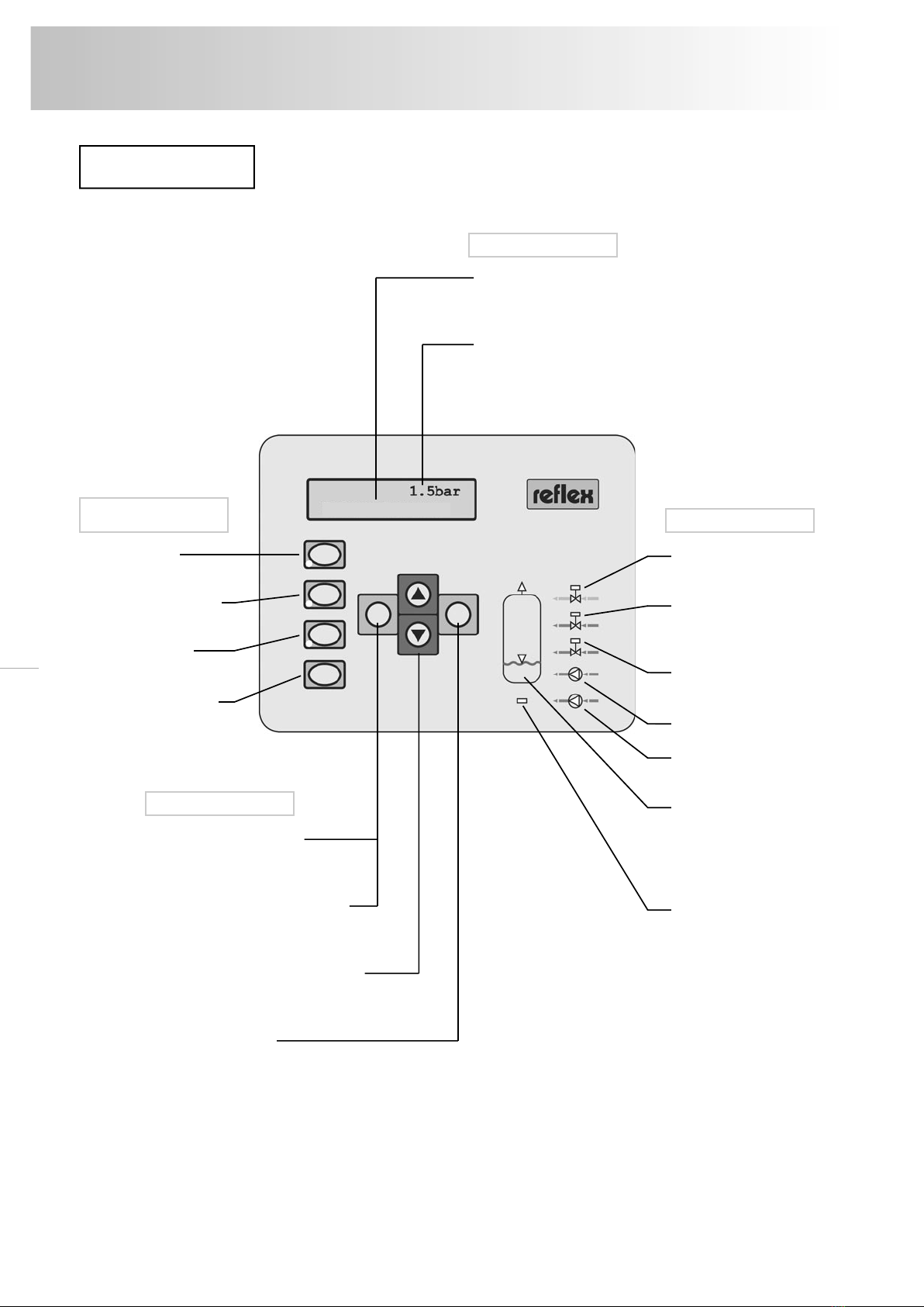
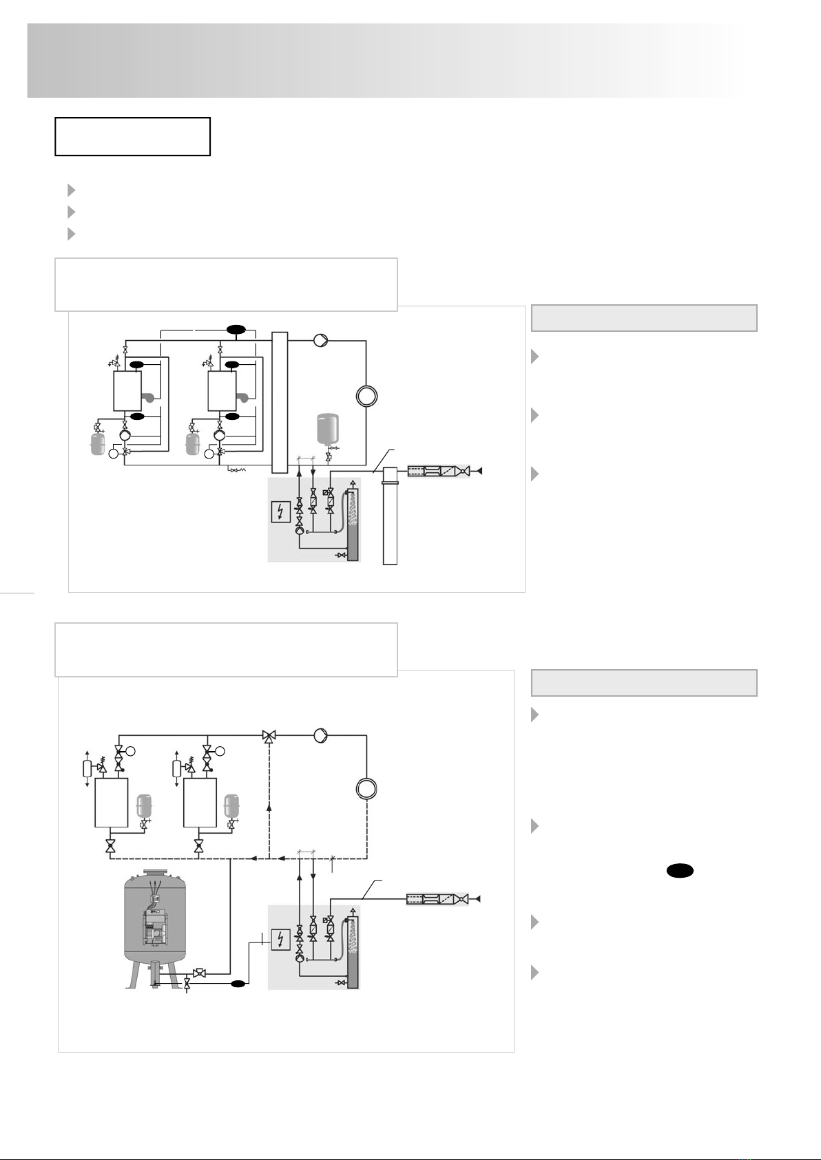
’servitec’ is a deaeration and make-up station mainly consisting of a control unit and a vacuum spray-tube.
The attached conformity certification certifies the compliance with the directive 97/23/EC for pressure devices and 89/336/EC
on the electromagnetic compatibility.
Installation, operation, pre-operation test, periodic inspections
according to the governing local regulations. The installation and the operation to be performed to the state of the art by
skilled installation technicians and specially trained personnel. An approved inspection body must be notified of necessary
tests before operation (only for ’servitec’ special systems, PS x V > 50 bar x litre) and after major changes in the installation,
as well as of periodic inspections. For recommended inspection intervals, see section “Periodic Inspection”. Only vacuum
spray-tubes without visible external damage to the pressure body may be installed and operated.
The operator is obliged to read thoroughly the installation, operating and instruction manual before installation/
initial start-up, to follow the instructions and to confirm the expert installation and start-up in the installation and
start-up certificate (→ p. 25). This is a warranty requirement. We recommend having the initial start-up and annual
maintenance performed by your Reflex Service (→ p. 21).
Attention! ’servitec’ is for the stationary, not for the mobile operation. The set warranty periods are only applicable if a
maximum of 16.000 deaeration intervals per year is observed (→ maintenance p. 20).
Changes to the ’servitec’,
for instance welding operations on the spray-tube or interventions into the wiring are not permissible.
Adherence to the parameters
Details concerning manufacturer, year of manufacture, serial number and the technical data are provided on the name plate.
Suitable safety measures for temperature and pressure protection in the supply unit must be taken to ensure the specified
permissible maximum and minimum operating parameters (pressure, temperature) are adhered to. Use only in systems with
non-toxic waters.
Thermal protection
In water heating systems, a warning instruction must be provided by the operator near the vacuum spray-tube if persons are
at risk from excessive surface temperatures or a suitable thermal insulation. Careful when working on a hot system. There is
a scalding hazard from water issuing especially from the screw connections, the bleed screw for the pump and the dipstick
tube-deaeration unit and injury hazard through high temperatures when touching especially the vacuum spray-tube.
Electrical connection
The electrical wiring and connection must be performed by a qualified electrician according to the applicable local EVU and
VDE regulations. De-energise the system before working on electrical components.
Failure to heed these instructions especially the safety instructions can result in the destruction of and defects of the ’servitec’,
endanger persons and impair operation. Any claims for warranty and liability are excluded if these instructions are violated.
5
reflex ’servitec’
General
General safety instructions

6
reflex ’servitec’
Installation
Note:
Please check the delivery for completeness and damage immediately after goods receiving! Transport damage must be
notified immediately!
The scope of delivery is described on the delivery note and the content indicated on the cardboard box.
(→ p. 3)
1 Pallet with outer cardboard box with - ’servitec’ (pre-assembled)
(content indicated on the outer - vacuum spray-tube (added in cardboard box)
cardboard box) - dipstick tube-deaeration unit (added in cardboard box)
with - foil pocket (attached to the ’servitec’) with
- installation, operating and maintenance instructions
- electric wiring diagram
Possible accessories:
1 cardboard box
- 'fillset' with water meter (added in cardboard box)
1 cardboard box
- 'fillset' with contact water meter (added in cardboard box)
Installation room requirements:
− Frost-free well-ventilated room, room temperature > 0 to max. 45 °C
− No unauthorized access
− Level floor with adequate load capacity with drainage facility
− Filling connection ND 15, according to DIN 1988 T 4
− Electrical connection to 230 V~, 50 Hz, 16 A with upstream fault
current protection switch: triggering current 0.03 A
− Remove ’servitec’ from the pallet and transport to the place of installation,
ensuring that the ’servitec’ is carried by the frame.
− When aligning the control unit ensure that the valves and feed facilities of
the connection lines can be operated.
− Install vacuum spray-tube (20) (nut M12).
− Connect the union nut of the suction connection (17) with the pump (10)
without any stress; insert the enclosed plastic washers if required.
− Connect connection hose (15) to manifold (9).
− Remove transport lock of the dipstick tube-deaeration unit (18) (see figure)
and manually screw in dipstick tube-deaeration unit (18).
− Retighten all screw connections.
− When replenishing from the potable water system the 'fillset' (→ p. 3)
or a system separator must be installed upstream.
− If no ’fillset’ is intended for connection to the potable water system, a dirt
trap (mesh size < 0.25 mm) must be installed upstream by the customer.
− If automatic make-up is not connected, the connection (R) of the
make-up line must be blanked off with a plug G 1/2".
Scope of delivery
Place of installation
Installation

≥ 500
Main flow V
circuit water
rich in gas low in gas
7
reflex ’servitec’
Installation
− connect ’servitec’ with the system piping. The maximum permissible media temperature at the connection
point is 70 °C (’servitec .../90 °C’ are applicable up to 90 °C), which is why it is installed in the system return
in the case of heating systems.
− connect in the immediate vicinity of the expansion line so that protection by way of the system safety valve
is provided. Otherwise, additional protection will be required.
− maintain a minimum distance between the connection points of 500 mm,
− note flow direction,
− rinse pipelines.
Installation diagrams
− Caution dirt! Connect connection lines from the top
or as immersion pipe as shown. Never integrate edgeless
from below (danger of contamination).
− With ’servitec .../gl’ a dirt trap (mesh size 0.25 mm) must
be provided in the overflow line O by the customer in
order to protect the additional solenoid valve (7) from
contamination.
− ’servitec’ deaeration operation is ensured only if ’servitec’
is connected to a representative main flow of the system.
The following minimum flow rates V must be maintained
during operation.
− Use the following pipe dimensions:
RO P
reflex ’fillset’
with potable water
make-up
reflex ’servitec’ Expansion vessel/
pressure maintenance
Detail
connection
20 2520
VpSV
Dewatering
by customer
max. 70 °C
Detail connection
R Make-up line
O Overflow line
P Pump line
V
servitec ... / 35
0.7 m³/h
servitec ... / 60
1.1 m³/h
≥ 500
Main flow V
circuit water
rich in gas low in gas
from above
from below as
immersion pipe
or laterally
welded edgeless
from below
not allowed
DN 25
DN 20
DN 20

8
reflex ’servitec’
Installation
Preferably install ’servitec’ on the
system side so that the temperature
exposure remains ≤ 70 °C.
When using softening systems, this
should be installed between ’fillset’
and ’servitec’.
If the shut-off at the connection point
of ’servitec’ is closed when shutting
down the circulating pumps, part flow
deaeration remains operational.
Notes to the installer:
reflex ’servitec magcontrol’ in a multiple boiler
system with hydraulic points and expansion vessel
The combination ’servitec’ with com-
pressor-controlled pressure-maintai-
ning stations (e.g. ’reflexomat’) is
especially recommended. The system,
which was highly degassed by the
’servitec’, is softly cushioned by the
’reflexomat’.
The water level in the expansion ves-
sel is monitored by the control unit of
the pressure maintaining station. The
230 V make-up signal LS of the
pressure maintaining station triggers
the make-up process with deaeration.
Optimum deaeration operation is en-
sured by connecting ’servitec’ in the
main circuit water flow.
On combining pump-controlled pre-
ssure maintaining stations with ’ser-
vitec’, we always recommend indivi-
dual boiler protection with a diaphragm
pressure expansion vessel
(e.g. ’reflex’).
Notes to the installer:
reflex ’servitec levelcontrol’ and compressor
pressure maintenance - an ideal combination
reflex ’servitec’ deaeration stations solve „gas problems“ in three ways:
no direct drawing in of air through controlled pressure maintenance
no circulation problems through free bubbles in the circuit water
reduction of corrosion risk through oxygen withdrawal from the filling and make-up water
* Detail connection → p. 7
The circuits must be adjusted to suit local conditions.
reflex ’fillset’
reflex ’servitec magcontrol’ Softening
Potable
water
MM
TIC
TIC
TIC
TIC
TIC
M M
Hydraulic points
202025
≥ 500*
≥ 500*
reflex ’fillset’
reflex ’servitec levelcontrol’’reflexomat’
Potable
water
202025
230 V
Signal
Cable by
customer
Main volumetric flow
Required flow pressure ≥ 1.3 bar
LS
Installation diagrams

9
reflex ’servitec’
Installation
Electrical connection
Electrical cabling and connection must be performed by a qualified electrician according to the applicable local
(EVU) and VDE regulations. Pull the mains plug or de-energise the system before commencing work on
electrical components. Comprehensive electrical connection diagrams are enclosed with these instructions
and must be adhered to.
The following information applies only to standard systems and is largely restricted to the connections required
by customer.
– loosen 4 cross-recess screws on the switching cabinet (13)
– open lid
– pass all cables to be connected through the PG screw connection.
Attention! Use only PG screw connections suitable for the appropriate cable.
– connect all cables (refer to the following and electrical wiring diagram).
– for on-site protection, observe the connected loads on p. 23.
Overview wiring diagram on the circuit board
J2 terminals 7/8 (fourth
from the left) occupied
→ Contact water meter
can be evaluated
Designation Terminal Signal Remarks
Feed X0 / 1 L - wiring on the terminal block next to the fuses
(230 V) X0 / 2 N - ’servitec’ is ready cabled with earthing plug
X0 / 3 PE
Feed X0 / 1 L1
(400 V) X0 / 2 L2
X0 / 3 L3 - feed on-site
X0 / 4 N
X0 / 5 PE
Make-up (4) 4 Y1
(230 V) 5 N - is connected
6 PE
Water deficiency 43 +24V DC - pass cable of the water deficiency switch (16)
switch (16) 45 through the M16 screw connection
for dry operation - pull plug from the circuit board and connect the
protection the cable of the water deficiency switch on the
outside in each case. Plug in the plug. The
terminals 43 and 45 must be occupied. Polarity
need not be observed.
Dry operation pro- 13 - to be cabled by customer (optional)
tection (floating) 14
Pump (230 V) 15 M1
'servitec 35 - 95' 16 N - is connected
17 PE
Pump (400 V) - is connected,
'servitec 120' → electrical wiring diagram

10
reflex ’servitec’
Installation, initial start-up
External make-up signal only for ’servitec levelcontrol’
Use in systems with pump or compressor-controlled pressure maintenance. Make-up of ’servitec levelcontrol’ is
controlled by way of an external signal:
– pass the control cable for make-up through the appropriate screw connection (M16 or M20).
– connect cable.
Once all connections have been established, close switching cabinet door, tighten the four screws of the
switching cabinet door and establish the power supply. The system version will appear in the display.
The ’servitec’ control is now ready for initial start-up.
Designation Terminal Signal Remarks
external make-up 22a only with ’servitec levelcontrol’
control 22b - floating input for external
230 V make-up signal
- cable example:
Aggregate mes- 23 NC
sage (floating) 24 COM - to be wired by customer (optional)
25 NO
Contact water 43 +24 V DC - to be cabled by customer, additionally connect the
meter (optional) 44 E1 the pins 7/8 on the jumper block J2 (see above figure)
Pressure 39 +18 V
transducer (2) 41 AE - is connected
42 PE
We recommend that you have the following operations and the induction of the operating personnel carried
out by your Reflex service (→ p. 21, chargeable service according to the applicable gross price list).
– The installation of the ’servitec’ including vacuum spray-tube has been completed.
– The water connection to the system has been established.
– System pressure maintenance is in operation.
– The connection system is at least roughly bled.
– The system has been connected to the electrical mains system according to the applicable VDE and local EVU
regulations.
Start-up requirements
'servitec'
230 V
22a
22b
'reflexomat'
4 (Y1)
5 (N)

The starting routine of the ’servitec’ is automatically called up when the
control is switched on for the first time. ’servitec’ type, for instance ’ser-
vitec magcontrol’ or ’servitec levelcontrol’ will then appear in the display.
Now press ok to get to the language selection:
Select the language by means of the country's symbols,
e.g. GB for the english language and confirm with ok.
The note to read these operating instructions will appear.
Confirm with ok.
This display appears only with ’servitec magcontrol’. Set the
minimum operating pressure according to the static head of your
system (refer also to the following diagram) and confirm with ok.
Example: Heating system
Advance temperature: 70 °C
(Evaporation pressure pD = 0 bar)
Static pressure pst:11 mWc
(11 mWc ~ 1.1 bar)
Setting values:
p0: = 1.3 bar
pSV: = 3.0 bar
Resulting pressures for
make-up:
ON: = 1.4 bar
OFF: = 1.6 bar
This display appears only with 'servitec magcontrol'.
Set the safety valve response pressure of the heat generator
and confirm with ok.
SERVITEC
.....
Country: GB
D GB F NL PL
Read operating
instructions!
Min.oper.press.
P0 = 1.5 bar
Saf.valve press.
PS= 3.0 bar
ok
ok
pSV [bar] = Safety valve response pressure on the heat generator
pmax [bar]
pe [bar] = End pressure maintenance
pa [bar] = Starting pressure maintenance
or filling pressure pF with expansion vessel
p0 [bar] = pstatic + pevaporation + 0.2 bar (recommended)
pst [bar] = static pressure (=static height [m] / 10)
0.3 bar
≥ 0.5 bar
≥ 0.3 bar
0...0.2 bar
The working pressure range of the 'servitec' must be within
the working range pa … pe of the pressure maintenance.
pa = Make-up if pressure falls below the limit
*
*
*Error message if pressure exceeds upper or falls below lower limits
The starting routine commences when the control is switched on for the first time. It serves for the setting of the
parameters required for the operation of ’servitec’. Should you have entered an incorrect value you can restart the
starting routine by pressing the „quit“ button.
Note: The starting routine can be run through only once, once this has been done parameter modifications and
cheques have to be performed in the customer menu (→ p. 16).
Starting routine
ok
ok
ok
reflex ’servitec’
Initial start-up
11

First, set the current hour (in this case: 18) with the arrow
buttons and confirm with ok. Then continue with minute (in this
case: 46) and seconds (in this case: 29).
First, set the current day (in this case: 29) with the arrow buttons
and confirm with ok. Proceed with month (in this case: 11) and
year (in this case: 01).
At the end of the starting routine the question will be asked
whether the operator wishes to leave the starting routine. If
„YES“ is chosen and confirmed with ok, the system will auto-
matically move into stop mode. It should initially also be left in
the stop mode in order to take additional start-up measures.
If „NO“ is selected, the starting routine is repeated.
You have completed the starting routine and are in Stop mode
(in this case: ’servitec magcontrol’ with pressure display).
You are now in stop mode.
Attention! Do not yet change to automatic
mode.
The ’servitec’ is in stop mode.
Careful with high temperatures! Observe general safety instructions
(refer page 5)!
– Connect filling hose to the
filling and draining ball valve
(21) of the vacuum spray-tube.
– Fill vacuum spray-tube, air is expelled through the dipstick tube-deaeration unit (18),
the potable water pressure can then be read off the vacuum gauge (19).
– Bleed the pump (10) by way of the bleed screw (12), the pump must not be running.
– Close bleed screw; close the
filling and draining ball valve
(21). Switch on pump.
Note:
Do not fully unscrew the bleed screw. Wait until bubble-free water runs out.
Repeatbleeding as required.
Careful with high temperatures! Observe general safety instructions (→p. 5)!
Perform the vacuum test conscientiously to guarantee the operation of the ’servitec’!
– Close ball valve (6), ball valve (1) of the pump line is open
Jump to manual mode
Start system deaeration (SE, flashes),
pump (10) starts after 50 seconds
Switch off pump, after approximately
10 seconds of pump operation
– Observe vacuum gauge (19), the pressure may not change within a period
of approximately 10 minutes. If the pressure has increased, please check the
screw connections on the vacuum spray-tube, the bleed screw (12) and dipstick
tube-deaeration unit (18) and repeat the process.
– If the vacuum test was successful - reopen the ball valve (6)
Time:
18:46:29
Date:
29.11.01
Exit routine
YES
1.7 bar
STOP
Filling and bleeding the pump
Vacuum test
hand
ok
ok
ok
12
reflex ’servitec’
Initial start-up

Hydraulic balancing
Hydraulic balancing is required in order to coordinate the perfor-
mances of the pump and the nozzle.
– For adjustment of the pressure reducing valves (5, 8) and the overflow valve (3),
loosen the safety screws
- Jump into manual mode
Start system deaeration (deaerating the
system water) (SE, flashes) and when
pump (10) is running,
– set overflow valve (3) to the set value on
the hand wheel (red), read pressure off
pressure gauge (the green display on the
hand wheel is only an orientation aid).
– Regulate pressure-reducing valve (8, blue)
of the overflow line to the set value and sub-
sequently observe a complete deaeration
cycle (→ p. 20): The water deficiency
LED should not light up and the gas must
be expelled before the next interval com-
mences with pump restart.
Quit system deaeration
– With make-up connected:
Start make-up deaeration (NE, flashes)
Regulate pressure-reducing valve (5, blue) of
the make-up line to the set value and check
the flow on the water meter of the make-up
line.
Quit make-up deaeration
Note:
To regulate the valves (3, 5, 8), read the flow pressures from the appropriate pressure
gauges. The pressure-reducing valve (5) for instance can only be set correctly with the
solenoid valve (4) open. After all set values have been adjusted, recheck on the respecti-
ve pressure gauge!
– Retighten the valve safety screws (3, 5, 8)
You can now change to automatic mode.
Note:
For the automatic mode of the 'servitec' it must be ensured that pressure mainte-
nance of the system is operational and hydraulically connected with the ’servitec’!
The system must have been roughly bled beforehand. Hydraulic balancing must
have been completed!
Start automatic mode „Permanent deaeration“
will appear in the display
The ’servitec’ is now in operation.
Commissioning by the reflex service is complete at this point!
hand
auto
Automatic mode
Pressure reducing valve
1.7 bar
Permanent degas.
Display (→ p. 4) after initial start-up
of a ’servitec magcontrol’
in automatic mode
Typ 35 : 3.2 bar
Typ 60, 60 gl : 5.2 bar
Typ 75, 75 gl : 5.7 bar
Typ 95, 95 gl : 7.9 bar
Typ 120, 120 gl : 9.7 bar
Typ 50/90 °C : 3.3 bar
Typ 75/90 °C : 5.3 bar
Typ 95/90 °C : 7.0 bar
Typ 120/90 °C : 8.7 bar
0.8 bar
1.0 bar
+ -
quit
quit
reflex ’servitec’
Initial start-up
13

Clean dirt traps
Caution! Observe general safety instructions (→ p. 5)!
Note:
After expiry of the set permanent deaeration period, clean the dirt traps of the pressure
reducing valves (5, 8) of the make-up and overflow lines (not part of reflex commissio-
ning!). Do not forget dirt traps (for instance ’fillset’ item F) installed by customer.
If the dirt traps are very dirty, fine setting (hydraulic balancing → p. 13) is required once
more.
The dirt traps should also be checked after the filling process or after extended opera-
tion.
– close ball valve (6), ball valve (1) of the pump line is open.
Jump to stop mode
– loosen union nuts of the valves (5, 8)
– pull out operating unit (black)
– clean dirt trap
– reinstall operating unit with dirt trap
– tighten union nut
– Open ball valve (6)
– Bleed the pump (10) by way of the bleed screw (12), the pump must not be running
– Close bleed screw (12)
– Start automatic mode
After the initial start-up, permanent deaeration is activated for 24 hours in a normal case,
automatically followed by intermittent deaeration (→ p. 15). Following permanent deae-
ration, clean the dirt traps of the pressure reducing valves (5, 8).
stop
auto
Dirt trap
Operating unit
Union nut
Initial start-up is completed at this point!
14
reflex ’servitec’
Initial start-up

15
Automatic mode
Automatic mode may only be activated after completed initial start-up. If the system is in
automatic mode, you can select from three deaeration programs if required. System cont-
rol is active with all three deaeration programs. Make-up takes place automatically.
Select from the customer menu (→ p. 16)
Permanent deaeration – Intensive deaeration after start-up and repairs
The deaeration cycles for the set continuous deaeration time (24 hours basic setting)
will be executed successively. The control will then proceed with intermittent degas-
sing automatically. On start-up, at least half of the system volume in the case of water
systems should flow at least once by way of the ’servitec’, in the case of water/glycol
mixtures, 5 times the system volume.
Interval deaeration – Economy mode in automatic mode
After 8 cycles (standard), a break (standard 12 hours) is observed before the next 8
deaeration cycles are started. This program is started automatically after the expiry of
continuous deaeration or can be selected manually with systems already degassed.
Interval deaeration will start at 08h00 each day.
Make-up deaeration – Only deaerating the make-up water
The system water will not be degassed. This operating mode is practical in summer
mode (→ p. 18) or if general deaeration of the system water is not required.
Manual mode is required for hydraulic balancing of the pressure reducing valves (5, 8)
and the overflow valve (3) and for filling systems. There are two types of operation in
manual mode: NE (make-up deaeration) and SE (system deaeration).
System deaeration SE – system water is degassed
System deaeration is active while is flashing.
Acknowledge system deaeration
The deaeration cycles (→ above) are successively executed in this type of operation.
The system deaeration is required for hydraulic balancing of the pressure reducing
valve (8) and the overflow valve (3) (→ p. 12). The maximum running period is
displayed at the bottom right. After expiry of this time, the ’servitec’ moves into error.
An error message will be output if the operating pressure falls below the minimum.
Make-up deaeration NE – make-up water is degassed
Make-up deaeration in manual mode is active for as long
as is flashing.
Acknowledge make-up deaeration
This type of operation primarily serves for hydraulic balancing of the pressure-reducing
valve (5) (→ p. 12). However, with ’servitec magcontrol’ it is also possible to fill the sys-
tem. The filling time (with contact water meter also the filling quantity) will be monito-
red. Once the filling pressure (pF, → p. 10) or the filling time (10 h) has been reached,
make-up deaeration is terminated and an error message output.
Again press the button to get to stop mode.
In stop mode 'servitec' is not operational except for the display. Operation monitoring
does not take place. All pumps or solenoid valves are switched off. The adjacent display
appears when the „stop“ button is pressed.
If the stop mode has been activated for longer than 4 hours, a message will be
initiated.
1.7 bar
Permanent degas.
Display (→ p. 4) automatic
mode with permanent deaera-
tion with ’servitec magcontrol’
auto
hand
1.7 bar
Interval degas.
Display (→ p. 4) automatic
mode with interval deaeration
with ’servitec magcontrol’
NSP
Make-up degas.
Display (→ p. 4) automatic mode
with make-up deaeration with
’servitec magcontrol’
NE SE 10 h
Display (→ p. 4) ’servitec level-
control’ flashes with system
deaeration
NSP
NE SE 010 h
Display (→ p. 4) ’servitec level-
control’ flashes with make-
up deaeration. NSP appears
with 230 V or floating make-up
signal
Manual mode
quit
quit
quit
Stop mode
stop
STOP > 4 h 19
STOP
reflex ’servitec’
Operation

menu
Customer menu
General
The customer menu serves to enter and change the most important ’servitec’ operating para-
meters. In part, these were already processed within the starting routine during initial start-up.
Additional parameter changes are possible here. Press the „menu“ button to get to the cus-
tomer menu. This is where you can change operating parameters or view current statuses.
Press the „menu“ button to access the customer menu. Press to leave the customer
menu.
This information appears in the display once the menu
button has been pressed. You are now in the customer
menu.
Select the language by means of the national
symbol, e.g. GB for the english language and
confirm with ok.
First, set the current hour (in this case: 18)
with the arrow keys and confirm with ok. Pro-
ceed with minute (in this case: 46) and second
(in this case: 29).
First, set the current day (in this case: 29) with
the arrow keys and confirm with ok. Proceed
with month (in this case: 11) and year (in this
case: 01).
This display appears only with ’servitec
magcontrol’.
Set the minimum operating pressure according
to the static head of your system (→ p. 11) and
confirm with ok.
This display appears only with ’servitec
magcontrol’.
Set the safety valve opening pressure (→ p. 11)
and confirm with ok.
Select the deaeration program (→ p. 20) and
confirm with the ok button.
Select the duration of permanent deaeration
(→ p. 15). The standard setting of 24 h is suf-
ficient for water systems up to approximately
20 m³ capacity. Confirm with ok.
Press , to get to the language selection:
Change
menu point
Select
parameters
Confirm
parameters
Leave
menu
Select or change parameters
(flashing values or symbols)
CUSTOMERMENU
Country: GB
D GB F NL PL
Time:
18:46:29
Date:
29.11.01
Min.oper.press.
P0 = 1.5 bar
Saf. valve pre ss
PS = 3.0 bar
Deaeration prog.
Permanent degas.
Cont. degas time
ED = 012.0 h
ok
ok
ok
ok
ok
ok
ok
ok
ok
quit
ok
ok
ok
ok
ok
quit
reverse
forward
Change menu option
16
reflex ’servitec’
Operation

17
The meter reading in litres of the contact wa-
ter meter (10 litres per contact) if applicable
can be reset here (YES). Confirm with the ok
button.
In this menu option it is possible to set the
total make-up volume from which an alarm
message will be triggered if more than 5000
litres have been replenished.
This is where you set when the message „re-
commended maintenance“ will be triggered.
The counter counts backwards, i.e. when dis-
playing 10 months the next maintenance will
be due in 10 months' time. The maintenance
control can be switched off.
Here you can select whether all active alarms
ought to switch the floating contact (pfK). If
„NO“ is selected here, only the messages
identified as „alarms“ in the message list on
page 18 will result in the pfK being switched.
Error memory display. This is where the last
20 faults including error code (for instance
ER01, → p. 18) are chronologically displayed
with the time and the date. 01 is the most re-
cent, 20 is the oldest error.
The parameter memory saves the last 10
changes of the minimum operating pressure
po specifying the time and the date of the
change. 01 is the most recent, 10 is the oldest
change.
Change
menu option
*
*
Select
parameters
Confirm
parameters
Select or change parameters
(flashing values or symbols)
Make-up vol.
Vnsp = 001460 l
Max-make-up-vol.
Vmax = 005000 l
Next maintenance
TY = 12 months
All messages PFK
YES
Error memory
Parameter
memory
ok
ok
ok
ok
ok
ok
Displays the ’servitec’ type and the software
version (for instance V1.04).
MC → ’servitec magcontrol’
LC → ’servitec levelcontrol’
* Only when a contact water meter is used
(plugging jumper → p. 10)
SERVITEC MC
V ...
auto
hand
stop
ok
ok
ok
ok
ok
ok
You have run through the complete customer
menu once. You can now change to the desired
operating mode.
CUSTOMERMENU
Leave
menu
quit
Reverse
Forward
Change menu option
Only for
information:
Only for
information:
Service menu
A password-protected service level is installed in ’servitec’ controls, in which additional data can be changed.
This is only possible by the Reflex service, telephone +49 23 82 / 70 69-550.
or
or
reflex ’servitec’
Operation

The following information is announced by way of this interface:
– Continuous information concerning pressure
– Information on the pump operating status (only ’servitec magcontrol’)
– Information of the operating status of the solenoid valve for make-up
– Information on the added value of the contact water meter
– Information on all messages
– Information from the error memory
Connection of the interface with the primary control centre or similar
– The interface is arranged on the display board in the switching cabinet door in the lower left corner. A four-pin
plug (plug-type LP terminal, grid 3.81 mm, 4-pin, type 8813B/04OB) is required for connecting the interface.
The plug can be obtained from the Reflex service.
– Connect the interface with a screened cable twisted or stranded together in pairs, e.g. LJYCY (TP), 4 x 2 x 0.8
(max. total bus length = 1000 m)
– When using a control centre or similar not equipped with an interface RS-485 but with an interface RS-232,
an appropriate interface converter is required.
– When using the communication module (optional) the interface is occupied by connecting the
communication module.
The protocol of the interface RS-485 can be requested from reflex service if required.
Interface RS-485
Summer operation
If the circulating pumps of the system are taken out of service during summer, deaeration of the mains content water
can only be safeguarded if the shut-off between overflow line and pump line of the ’servitec’ is closed. If this cannot be
ensured, the deaeration program should be set to make-up deaeration by way of the customer menu (→ p. 16).
If the ’servitec’ was operated in the operating type make-up deaeration during summer, it should be reset to intermittent deae-
ration or, if desired, to continuous deaeration after the circulating pumps have been switched on again.
Sticking of the pump (10) is avoided through the positive start (24 h). Sticking of the pump cannot be excluded after prolonged
disuse (’servitec’ de-energised or in stop mode). For this reason the pump rotor should be turned with the screwdriver prior to
restarting.
Standard settings
Parameters have been reset in the data memory of the ’servitec’ which are based on research and operating experience.
The most important are described in the following table.
Parameter Setting Remark ’servitec ’servitec
magcontrol’ levelcontrol’
Pressure
Make-up ON p0 + 0.1 bar p0 min. operating pressure (→ p. 10) X
Make-up OFF p0 + 0.3 bar X
Pressure below minimum level = p0 X
Pressure above maximum level pSV – 0.2 bar pSV safety valve response press. (→ p. 10) X
Max. make-up volume 0 Only activated if control is set to contact X
water meter (→ p. 9)
Make-up The alarm message is triggered when
Max. make-up time 20 min the make-up time or number of X X
Max. make-up cycles in 2 h 3 cycles has been exceeded X X
Filling Filling is terminated after 10 hours or on
Maximum filling time 10 h reaching the filling pressure (p0 + 0,3 bar) X
Deaeration interval Standard / gl
Draw vacuum 02 s / 20 s Pump running, no spraying X X
Injection time 30 s / 00 s Pump running, spraying X X
Pushing out time 50 s / 50 s Pump off, spraying X X
Idle time 05 s / 05 s Pump off, no spraying X X
Interval-permanent deaeration
Intermission 12 h 8 deaeration cycles are run every X X
Deaeration cycles 8 12 hours X X
Starting time interval deaeration 08 h 00 Interval deaeration will start at 08h00 X X
each day (synchronization)
Permanent deaeration time 24 h adjust time to the consumer system X X
18
reflex ’servitec’
Operation

19
reflex ’servitec’
Operation
Active messages are displayed in the message line of the display. In addition to this the error LED lights up (red). The dry
operation protection is signalled directly by a separate LED (→ p. 4). If several messages are active simultaneously, these
can be directly displayed with .
Most of the messages automatically acknowledge themselves once the cause has been remedied. Errors such as „make-up
time 06“ or „make-up cycle 07“ must be acknowledged manually.
An error and parameter memory is available for subsequent analysis (→ p. 16). For remote transmission it is possible to use
the floating changer for the aggregate message, the floating contact for the dry operation protection and the RS-485 inter-
face (→ p. 17). In the customer menu (→ p. 16) it is possible to select whether only the messages characterised as alarms
or all messages will pass through the floating output.
Messages
ER Code Type of error Cause of errors Troubleshooting remedy
01 Pressure below – Water loss in the system – Correct leak
minimum pressure p0 – Pressure maintenance incorrectly set – Acknowledge error („quit“ button)
(alarm) or defective
02.1 Dry operation protection – Water deficiency switch (16) not wired up – Wire up water deficiency switch
Time exceeded – No water enters the vacuum spray-tube
(alarm) - Ball valve on inlet side closed – Open ball valve
- Dirt trap of the pressure reducing valves – Clean dirt trap
(5,8) dirty
02.2 Dry operation protection – Not enough water flows into the vacuum
Number exceeded spray-tube
(alarm) - Dirt trap of the pressure reducing – Clean dirt trap
valves (5,8) dirty
- Pressure reducing valves (5,8) or – Correct pressure setting on the pres-
overflow valve (3) incorrectly set sure reducing valves, perform hydraulic
balancing
– Dipstick tube-deaeration unit (18) defective – Replace dipstick tube-deaeration unit
04.1 Pump – Pump fuse defective – Check fuse, replace if required
fault – Pump blocked – Free pump
(alarm) – Short circuit – Establish cause and rectify
06 Make-up time – Major leaks in the system – Correct leaks, acknowledge error
exceeded (standard 20 min) – Make-up time inadequate for – Reduce make-up hysteresis
downstream pressure maintenance of the pressure maintenance
07 Make-up cycles – Minor leaks in the system – Correct leaks, acknowledge error
exceeded (standard 3 in 2 h) message
08 Pressure measurement – Pressure measuring transducer not – Check wiring, replace if required
fault (alarm) connected or defective
10 Max. pressure – Pressure losses between ’servitec’ – Incorporate pressure measuring trans-
exceeded and system excessive ducer in the system or use greater no-
minal widths for the piping to the system
– Expansion vessel in the system with – Check expansion vessel pre-pressure
incorrect pre-pressure
– Solenoid valve (4) fails to close – Inspect solenoid valve for dirt,
clean or replace if required
– PS in customer menu set too low – Co-ordinate PS setting with safety valve
activation pressure of the system
11 Make-up quantity – Major leaks in the system – Correct leaks, acknowledge error
within a make-up cycle – Make-up quantity inadequate for – Reduce make-up hysteresis of
exceeded downstream pressure maintenance the pressure maintenance or increase
maximum make-up quantity
12 Filling time – Max. filling time exceeded – Check filling status of the system,
exceeded (standard 10 h) acknowledge error and refill if required
13 Filling quantity – Max. filling quantity exceeded – Check the filling status of the system,
exceeded acknowledge error and refill if required
15 Make-up solenoid valve – Make-up solenoid valve (4) leaking – Inspect solenoid valve for dirt,
(control) (contact water meter is counting without clean or change if required
make-up request)
16 Power failure – – Check power supply
19 Stop > 4 h – ’servitec’ has been in stop mode for – Activate auto mode as applicable
more than 4 h
20 Max. make-up quantity – The maximum make-up quantity set in – Acknowledge message
exceeded (added) the customer menu has been exceeded
(→ p. 16)
Mainten. Maintenance interval – Reminder of the minimum annual – Perform maintenance
rec. expired maintenance – Acknowledge message
30 EEPROM defective – EEPROM has internal – Change CPU board
(alarm) calculation errors
*
*
*
*
* Only if contact water meter is connected and activated in the control (→ p. 10 and 15)

Maintenance
Caution! Observe general safety instructions (→ p. 5)!
The ’servitec’ must be maintained annually, but at least after 16.000 deaeration cycles (this corresponds to a continuous dea-
eration time of approximately 14 days or a continuous deaeration time of 7 days + 1 year intermittent deaeration with standard
setting). Maintenance operations may only be performed by specialists. We always recommend that you commission your
Reflex service.
To remind of the maintenance to be performed at least annually, the display "maintenance recommended" appears after expiry
of the set operating time, which can be acknowledged with the „quit“ button.
When carrying out maintenance operations on the vacuum spray-tube proper, this should first be depressurised by way of the
filling and drain cock (21).
Leak test
– check for external leaks, especially pump, screw connections and dipstick tube-deaeration unit
– seal if required
Operational vacuum test
– Procedure → p. 11, paragraph vacuum test
Cleaning filter elements of the pressure-reducing valve (5, 8)
– Procedure → p. 13, paragraph clean dirt trap
Adjust pressure-reducing valves (5, 8) and overflow valve (3)
– Procedure → p. 12, hydraulic balancing
Check set values of the control
– Procedure → p. 15, customer menu
Check deaeration interval
System deaeration
– Jump into manual mode
– Start system deaeration (SE, flashes)
– Following the expiry of the push-out time (50 s) the pump (10) starts;
vacuum is drawn, can be read off the vacuum gauge (21)
– Pump (10) switches off (after 30 seconds or 20 seconds with gl),
water deficiency LED may not light up
– Version gl solenoid valve (7) opens when the pump is switched off
– Water is sprayed in by way of the pressure connection with nozzle (22),
vacuum is broken, gas is expelled,
gas must be expelled before the next cycle can commence
Make-up deaeration
– Start make-up deaeration (NE, flashes)
– Solenoid valve (4) of the make-up opens, the pump starts after
50 seconds and draws vacuum
– Pump switches off (30 seconds or 20 seconds)
– Water continues to be sprayed in via nozzle (22), vacuum is broken,
gas is expelled,
gas must be expelled before the next cycle can commence.
– Deactivate make-up deaeration (NE, no longer flashes)
Note:
Once the gas has been completely expelled through the dipstick tube-deaeration unit and the
water deficiency LED (red) has not come on during the injection process, maintenance is complete.
– Start automatic mode
hand
auto
1.7 bar
NE SE 10 h
Display (→ p. 4) ’servitec mag-
control’ flashes with system
deaeration
1.7 bar
NE SE 10 h
Display (→ p. 4) ’servitec mag-
control’ flashes with make-up
deaeration
quit
20
reflex ’servitec’
Maintenance
Other manuals for Servitec
2
Table of contents
Other Reflex Industrial Equipment manuals

Reflex
Reflex Reflexomat Installation instructions

Reflex
Reflex Fillcontrol Auto User manual

Reflex
Reflex Servitec 35 User manual

Reflex
Reflex Exdirt Magneto Installation instructions

Reflex
Reflex Fillcontrol Auto User manual

Reflex
Reflex Reflexomat RS 90/1 User manual

Reflex
Reflex Storatherm HF R2 Series Installation instructions

Reflex
Reflex Fillcontrol Plus Compact Installation instructions

Reflex
Reflex longtherm User manual

Reflex
Reflex Servitec 35-120 User manual