manuals.online logo
Brands
  1. Home
  2. •
  3. Brands
  4. •
  5. Rexnord
  6. •
  7. Industrial Equipment
  8. •
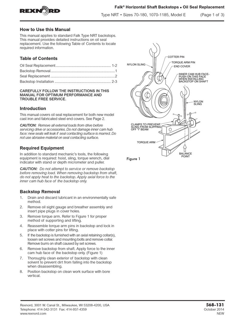
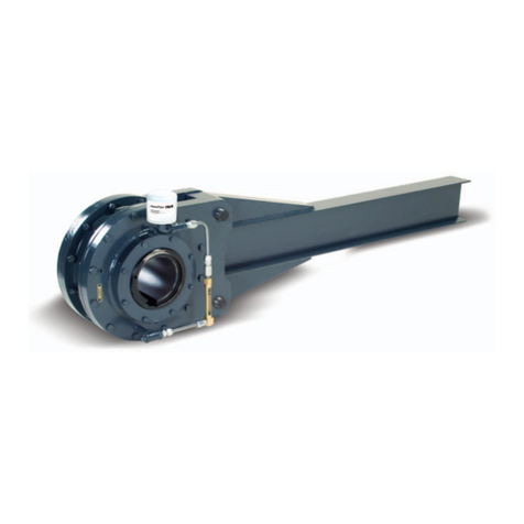
  9. Rexnord Falk NRTH B 1055 Maintenance and service guide

Rexnord Falk NRTH B 1055 Maintenance and service guide

How to Use this Manual
The following instructions and recommendations apply to
standard Falk 1055, 1065, & 1085 NRTH Style B backstops.
Their performance and life depend largely upon how they are
installed and serviced. Drawings are representative of this
series of backstops.
When requesting information specify the M.O. number,
backstop size, model number, maximum running rpm, torque
rating, and date indicated on the backstop nameplate.
This manual provides detailed instructions on installation,
maintenance, and parts identification. Use the following Table
of Contents to located required information.
Table of Contents
General Information .........................Page1
Description and Operation ....................Page1
Safety Codes and General Precautions............Page1
Application Requirements ....................Page1-2
General Instructions .........................Page3
Long Term Storage ..........................Page3
Installation ..............................Page3-4
Lubrication ...............................Page4
Maintenance ..............................Page4
CAREFULLY FOLLOW THE INSTRUCTIONS IN THIS
MANUAL FOR OPTIMUM PERFORMANCE AND TROUBLE
FREE SERVICE.
Introduction
Rexnord True Hold backstops are precision built safety devices
designed to protect inclined conveyors or vertical elevators
from the dangers of gravity accelerated reverse runaway. To be
assured of reliable protection and the longest possible service
life, it is important that the following recommendations be
observed for the installation, lubrication, and maintenance of
Rexnord backstops.
As soon as the backstop has been received, examine it
carefully for damage that may have occurred in transit and
report any breakage to the transit company and Rexnord
immediately. All tags and bulletins attached to the backstop
should be carefully read before placing the backstop in
operation and then filed for future reference.
The various component parts referred to may be readily
identified from Figure 1 on Page 2.
ALL BACKSTOPS ARE SHIPPED WITH OIL — Although all
backstops are shipped from the factory with oil, it is important
to check lubrication levels prior to operation.
If the backstop is to be stored for an extended period of time
(over 3 months) before installation, see the Long Term Storage
section on Page 3 for instructions.
Warranty — Rexnord Industries, LLC (the ”Company”)
warrants that Drive One gear drives (I) conform to Company’s
published specifications, and (II) are free from defects of
material for three years from the date of shipment.
Company does not warrant any non-Company branded
products or components (manufacturer’s warranty applies) or
any defects in , damage to, or failure of products caused by:
(I) dynamic vibrations imposed by the drive system in which
such products are installed unless the nature of such vibrations
has been defined and accepted in writing by Company as a
condition of operation; (II) failure to provide suitable
installation environment; (III) use for purposes other than those
for which designed, or other abuse or misuse; (IV)
unauthorized attachments, modifications or disassembly, or (V)
mishandling during shipping.
Safety Codes & General Precautions
Warning: Consult applicable local and national safety codes
for proper guarding of rotating members. Lock out power
source and remove all external loads from drive before
servicing drive or accessories.
DISMANTLING, REPAIR & PARTS REPLACEMENT — See
Figure 1, Page 2. The backstop and normal associated
equipment (shaft, pulleys, etc.) involve moving parts, therefore
consult local, state, OSHA and ANSI safety codes for proper
guarding of revolving parts and possible pinch points. (A pinch
point occurs at the contact point between the backstop torque
arm and support, and between the torque arm and stirrup.)
Carefully read and follow all supplementary instructions and
tags attached to the backstop and then file for future
reference.
Operate the backstop within the torque rating and overrunning
speed, listed on the nameplate. Follow installation and
lubrication instructions in this manual.
When removing backstop from shaft, do not apply heat to the
backstop. Apply axial force to the hub (inner race) of the
backstop only.
Damage may occur to the backstop if it remains inoperative
under full load for extended periods of time.
If the shaft was accidentally rotated in the wrong direction of
rotation at start-up, the backstop may have been damaged.
Return the backstop to the Factory for inspection.
Falk NRTH Style B backstops use a sprag design that does not
allow motion in one direction and runs freely in the other
direction.
Application Requirements
BACKSTOP APPLICATION — The 1055, 1065, & 1085
NRTH Style B backstops are designed to prevent reverse
rotation in applications such as inclined conveyors, bucket
elevators, fans, rotary pumps and kilns. If local safety codes
permit, the backstop may be used as a backup or a brake on
these applications, but NOT in people conveying systems such
as elevators, manlifts, ski tows or ski lifts. Also DO NOT use
the backstop as a substitute for a brake.
OPERATING TEMPERATURES — Enclosure of the backstop
may cause overheating. Provide adequate ventilation.
Backstop operating temperatures, at maximum overrunning
speed, may exceed 90°F (50°C) above ambient. Determine
the effect of this temperature on the driven equipment and
provide cooling if necessary.
If a backstop operates in the sun at ambient temperatures over
100°F (38°C), then special measures should be taken to
protect the backstop from solar energy. This protection can
consist of a canopy over the backstop or reflective paint on
Rexnord Industries, LLC, Geared Products, P.O. Box 492, Zip 53201-0492 568-102
3001 W. Canal St., Zip 53208-4200, Milwaukee, WI USA Telephone: 414-342-3131 July 2006
Fax: 414-937-4359 e-mail: [email protected] web: www.rexnord.com Supersedes 2-05
Falk™ Horizontal Shaft Backstops •Installation & Maintenance
Type NRTH Style B •Sizes 1055, 1065, & 1085 (Page 1 of 4)
the backstop. If neither is possible, a cooling device such as a
fan may be required to prevent the backstop temperature from
exceeding the allowable maximum of 200°F (93°C).
INDEXING — NRTH backstops can be used for indexing
service. Refer application data to the Factory for selection.
Indexing is defined as continuous cyclic or periodic application
of the backstop as encountered in conversion of reciprocating
or oscillating motion into intermittent linear motion.
JOGGING — Defined as start/stop movement with jerking or
jolting motion is not permissible.
EXPLOSIVE ATMOSPHERES — The purchaser is responsible for
taking adequate precautions to prevent spark generation in
explosive atmospheres. Consideration should be given to spark
generation that may occur when the torque arm strikes the stirrup.
CHEMICAL ATMOSPHERES — The backstop may be
damaged if exposed to certain types of chemicals or vapors:
for example, potash dust, chlorine gas, carbon tetrachloride,
etc. These materials may cause deterioration of the seals.
AXIAL RETENTION — Refer to Page 3, Installation section,
Paragraph B for Axial Retention.
Rexnord Industries, LLC, Geared Products, P.O. Box 492, Zip 53201-0492568-102
3001 W. Canal St., Zip 53208-4200, Milwaukee, WI USA Telephone: 414-342-3131July 2006
Fax: 414-937-4359 e-mail: [email protected] web: www.rexnord.comSupersedes 2-05
Installation & Maintenance •Falk™ Horizontal Shaft Backstops
(Page 2 of 4) Type NRTH Style B •Sizes 1055, 1065, & 1085
5
14
2
10
6
9
1
12
3
7
4
813
11
15
F
R
E
E
F
R
E
E
Figure 1
TABLE 1 — List of Components
Item Description Quantity
1Inner Race 1
2Outer Race 1
3Sprag Cage 1
4Cover Plate 2
5Gasket 2
6Bearing 2
7Oil Seal 2
8Retainer Ring 2
9Grease Fitting 4
10 Fastener 24
11 Shaft Key 1
12 Setscrew 4
13 Oil Plug 4
14 Breather Plug 1
15 Torque Arm 1
TABLE 2 — Torque Arm Reaction Force
NRTH Size Force (lb)
1055 5556
1065 7222
1085 7059
Force =1.5 x Catalog Torque Rating (lb - ft) x 12
.9 (F) in
See Figure 2 for (F) Dimension
General Instructions
BACKSTOP-SHAFT FITS — The shaft must have a 125 micro
inch (3,2 micro meters) or finer finish and clearance fits
specified in Table 3 above.
KEYS & KEYWAYS — Keys to be used with 1055, 1065, &
1085 NRTH backstops are furnished by Rexnord. They are
mild steel. The keys are side-fitted, full length, and must not be
excessively tight in order to avoid distortion of the inner race.
BACKSTOP MOUNTING POSITIONS — The backstop
rotational axis must be horizontal within 5° for all applications.
The NRTH backstop torque arm is capable of being mounted
at any desired angle, however a horizontal mounting at 0° or
180° is preferred.
TORQUE ARM STOPS (OR STIRRUP) — The torque arm
stops must be designed to resist the force developed by the
actual torque applied to the backstop.
The minimum recommended distance to the torque arm stop
is as illustrated in Figure 2 below. Use torque arm stops
capable of withstanding the torque arm reaction force. (See
Table 2)
The torque arm must be free to move within the stirrup or on
pin. Provide clearance on three sides per Figure 2 below.
DO NOT restrict torque arm movement by welding or securing
the torque arm to any supporting structure.
Locate the torque arm support surface parallel (±1/2°) to the
torque arm surface.
Prevent accumulation of any foreign material or ice around
torque arm and torque arm stirrup which could restrict free
movement of the torque arm.
Long Term Storage
Backstop should be completely filled with Dexron III automatic
transmission fluid. Backstops should be stored inside, if
possible, in a clean and dry area. Once every two months the
inner race should be rotated by hand to lubricate the rotating
elements.
Exposed, unpainted surfaces should be “brush painted” with a
rust preventative.
Before placing the backstop in operation, completely drain
and properly refill per lubrication section on Page 4.
Installation
A. Check for proper free shaft rotation - The backstop is
symmetrical, which allows it to be mounted for the desired
direction of free shaft rotation by rotating it end for end.
The arrow inscribed on the face of the inner race (Part #1)
indicates the direction of free shaft rotation. Before
mounting the backstop on the shaft, be sure to check
direction of free rotation.
B. Axial Retention - Since backstops are not a tight fit on
shafts, it is important to utilize the inner race setscrews (Part
#12) to prevent the backstop from “walking” on the shaft,
as this may cause end of the torque arm to contact the
stirrup and cause premature bearing failure.
After the backstop is mounted on the shaft, tighten all (4)
setscrews in the inner race. In the event that the backstop is
to overhang the shaft, it is permissible to only tighten the
two inboard setscrews. Setscrews should be tightened to
5-7 Lb-Ft.
C. Mount Backstop on Shaft - Backstop bores are finished to
size for an easy push fit on a shaft that is straight and not
tapered.
Coat the shaft with an anti-seizing agent or light oil for
easy mounting and future removal of the backstop.
Check again to make certain that the arrow on the
backstop inner race face is in the same direction as the
desired free shaft rotation.
If the torque arm (Part #15) is to be mounted on the
inboard face of the backstop, then slip torque arm onto the
shaft prior to mounting the backstop.
Push the backstop onto the shaft, taking care to push only
on the face of the inner race, thus eliminating undue abuse
on the bearings within the backstop.
Rexnord Industries, LLC, Geared Products, P.O. Box 492, Zip 53201-0492 568-102
3001 W. Canal St., Zip 53208-4200, Milwaukee, WI USA Telephone: 414-342-3131 July 2006
Fax: 414-937-4359 e-mail: [email protected] web: www.rexnord.com Supersedes 2-05
Falk™ Horizontal Shaft Backstops •Installation & Maintenance
Type NRTH Style B •Sizes 1055, 1065, & 1085 (Page 3 of 4)
K
J
F
1.25
0.5" TO 1.0”
CLEARANCE
BOTH SIDES
.50” CLEARANCE
0.75” CLEARANCE
1.125
PIN DIA.
0.5" TO 1.0”
CLEARANCE
BOTH SIDES
ARM RETENTION PIN RETENTION
+.000
– .010
A
A
E
REQUIRED FOR SIZE 1085
TABLE 3 — Backstop Shaft Fits
Nominal
Diameter
Nominal Shaft
Tolerance
Nominal Bore
Dia Tolerance
Bore - Shaft Min-
Max Clearances
Inch
1.7500-2.9375 +.0000, –.0010 +.0005, +.0015 .0005 – .0025
3.0000-5.4375 +.0000, –.0010 +.0010, +.0025 .0010 – .0035
Metric
45 to 50 k6 .002/.018 k6 .025/.050 F7 .007/.048
50 to 80 m6 .011/.030 m6 .060/.090 E7 .030/.079
80 to 120 m6 .013/.035 m6 .072/.107 E7 .037/.094
120 to 140 m6 .015/.040 m6 .085/.125 E7 .045/.110
Figure 2
ViewA-A
SIZE E F J K
1055 2364 4
1065 2364 4
1085 551610
Do Not Force Backstop Onto Shaft — Evidence of damage
during assembly caused by disregard of the above instructions
is readily traceable and Rexnord will not be held responsible
for failure of such affected part(s).
Do Not Use Tapered Keys. Keys Must Be Straight —Install
the key provided (Part #11) into the keyway. If necessary, the
key may be “field-dressed” to accommodate proper fit. The
key should be “side-fitted”. To provide for adequate top of key
clearance, the straight keyway in the bore of the backstop has
been made slightly deeper than standard.
For backstops installed at the end of the shaft, an end cover
can be provided to enclose the rotating components. Consult
local and national safety codes for proper guarding of rotating
components.
Attach Torque Arm to Backstop (After
Rotation Check)
Before attaching the torque arm, rotate the outer race (Part
#2) of the backstop so that one of the oil plugs (Part #13) is
near the 12 o’clock position. Attach torque arm to the
backstop with the fasteners provided (Part #10). Torque arm
fasteners for Sizes 1055 & 1065 should be tightened to
110-130 lb-ft and to 220-260 lb-ft for Size 1085.
Do not fasten torque arm end rigidly to steel framework
in angular or axial position.
Torque arm end should have a minimum of 0.50” top
clearance in its stirrup to make certain that it does not rust in
or pack tight with foreign matter. Approximately 0.5 to 1.0”
clearance should be provided at each side of the torque arm
for axial positioning.
Refer to Table 2 on Page 2 for required torque arm stirrup
load capacities.
The backstop must be centered on the shaft to prevent possible
bearing damage from misalignment that might occur if the
torque arm is held rigid. Also, if the end of the torque arm is
twisted crosswise, a pinching action may be imposed on the
bearings and cause damage.
If the shaft alignment position changes in time, the previous
precautions will allow the backstop to remain centered on the
shaft without danger of pinching or skewing caused by a
rigidly fastened torque arm end.
Safe backstop mounting is possible at any desired angle of the
torque arm. However, straight vertical mounting is not
recommended. A minimum angle of approximately 5 degrees
from vertical should be maintained.
If mounted downward through a floor slot, a suitable boot or
hood should be placed around the torque arm at or above the
floor level to keep foreign matter from restricting possible
torque arm movement at the floor opening.
Install Breather Plug
After the torque arm has been attached, remove the pipe plug
near the 12 o’clock position and replace it with the breather
plug provided (Part #14).
When the operating temperature increases and the air in the
backstop expands, the expanding air will easily pass through
the breather plug and not force oil through lip seals.
Lubrication
These backstops are filled at the factory with DEXRON III
Automatic Transmission Fluid. Contact the Factory if alternative
lubrication is to be used.
CAUTION: Oils containing high lubricity or EP additives must
not be used in backstops. Never use carbon tetrachloride,
which is detrimental to neoprene seals.
WARNING: The use of improper lubricants could cause a
malfunction resulting in equipment damage.
To Fill With Oil
a) Remove breather plug and one of the oil plugs in either the
3 o’clock or 9 o’clock position.
b) Slowly add clean oil through the breather plug hole.
c) Continue adding oil until it starts to drain from the side
hole.
d) Reinstall the oil and breather plugs.
Maintenance
Lubrication maintenance should not be performed while
equipment is in operation.
In order to provide proper lubrication maintenance, the
following procedures are recommended:
At least every 3 months, purge the grease seals from all (4)
grease fittings (Part #9) with a non-E.P. NLGI grade 1 or 2
grease such as Lubriplate “Aero” or “Mobilith 2”. Continue to
add clean grease until all “dirty” grease is purged from the
grease seal.
At least every 3 to 6 months: (Also After First Week of
Operation)
a) Thoroughly clean around breather plug. Remove the
breather plug and clean if dirty.
b) Drain oil from the backstop using the oil plug at the 6
o’clock position.
c) Reinstall oil plug.
d) Remove one of the oil plugs at either the 3 o’clock or 9
o’clock position.
e) Slowly add clean oil through the breather plug hole.
f) Continue adding oil until it starts to drain from the side
hole.
g) Reinstall oil and breather plugs.
h) Retighten coverplate bolts after first week of operation.
If coverplate bolts and oil plugs are kept tight, then the
frequency with which the backstop’s lubrication should be
inspected is an important consideration and can only be
determined by individual experience. However, it is considered
desirable to inspect the oil level of the backstop once a week
for the first month of service. The results of these inspections
will dictate the frequency of future inspections, but in any event
should not exceed three to six month intervals. Under severe
working conditions, it may be necessary to perform lubrication
maintenance on the backstop more frequently.
Additional lubrication in the sprag assembly can cause
the backstop to fail.
Rexnord Industries, LLC, Geared Products, P.O. Box 492, Zip 53201-0492568-102
3001 W. Canal St., Zip 53208-4200, Milwaukee, WI USA Telephone: 414-342-3131July 2006
Fax: 414-937-4359 e-mail: [email protected] web: www.rexnord.comSupersedes 2-05
Installation & Maintenance •Falk™ Horizontal Shaft Backstops
(Page 4 of 4) Type NRTH Style B •Sizes 1055, 1065, & 1085

This manual suits for next models

2

Other Rexnord Industrial Equipment manuals

Rexnord Falk GL32 Maintenance and service guide

Rexnord

Rexnord Falk GL32 Maintenance and service guide

Rexnord SURE-flex User manual

Rexnord

Rexnord SURE-flex User manual

Rexnord Falk NRT Use and care manual

Rexnord

Rexnord Falk NRT Use and care manual

Rexnord Falk GC02 Instruction Manual

Rexnord

Rexnord Falk GC02 Instruction Manual

Rexnord Falk NRT E 70 User manual

Rexnord

Rexnord Falk NRT E 70 User manual

Rexnord Falk Lifelign G66 User manual

Rexnord

Rexnord Falk Lifelign G66 User manual

Rexnord DTS-C 2000 Installation and operation manual

Rexnord

Rexnord DTS-C 2000 Installation and operation manual

Rexnord Hydro-flow Series User manual

Rexnord

Rexnord Hydro-flow Series User manual

Rexnord Falk Freedom M20 Maintenance and service guide

Rexnord

Rexnord Falk Freedom M20 Maintenance and service guide

Rexnord Falk SteelfIex T10 Series Maintenance and service guide

Rexnord

Rexnord Falk SteelfIex T10 Series Maintenance and service guide

Rexnord AUTOGARD 400 Series User manual

Rexnord

Rexnord AUTOGARD 400 Series User manual

Rexnord FALK HF132 Maintenance and service guide

Rexnord

Rexnord FALK HF132 Maintenance and service guide

Rexnord Thomas XTSR52 Instruction Manual

Rexnord

Rexnord Thomas XTSR52 Instruction Manual

Rexnord Thomas Tpack 52 Series Instruction Manual

Rexnord

Rexnord Thomas Tpack 52 Series Instruction Manual

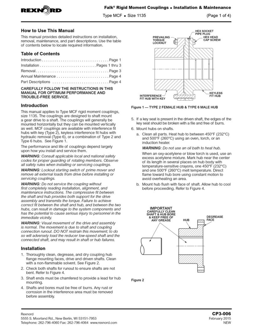
Rexnord Falk MCF 1135 Maintenance and service guide

Rexnord

Rexnord Falk MCF 1135 Maintenance and service guide

Rexnord Falk  Steelflex T10 User manual

Rexnord

Rexnord Falk Steelflex T10 User manual

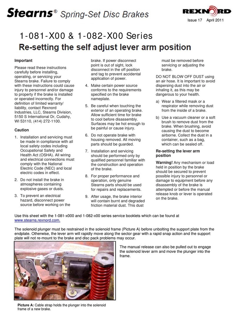
Rexnord Stearns 1-081-X00 Series User manual

Rexnord

Rexnord Stearns 1-081-X00 Series User manual

Rexnord Falk GL20 Instruction Manual

Rexnord

Rexnord Falk GL20 Instruction Manual

Rexnord Falk  Steelflex T10 Maintenance and service guide

Rexnord

Rexnord Falk Steelflex T10 Maintenance and service guide

Rexnord Hansen TRANSMISSION PENCOflex User manual

Rexnord

Rexnord Hansen TRANSMISSION PENCOflex User manual

Popular Industrial Equipment manuals by other brands

Douglas BDW-HD-BH-EL Operation guide

Douglas

Douglas BDW-HD-BH-EL Operation guide

Danfoss MCD 200 Series Service manual

Danfoss

Danfoss MCD 200 Series Service manual

Pepperl+Fuchs PGV100R-F200-R4-1.5M manual

Pepperl+Fuchs

Pepperl+Fuchs PGV100R-F200-R4-1.5M manual

Desoutter TRA 12 1600 P UNI user manual

Desoutter

Desoutter TRA 12 1600 P UNI user manual

ermengineering SK-270 Use and maintenance manual

ermengineering

ermengineering SK-270 Use and maintenance manual

EASTMAN Kodak X-Omat 180 LP Service manual

EASTMAN

EASTMAN Kodak X-Omat 180 LP Service manual

Swegon IBISa Installation, commissioning maintenance

Swegon

Swegon IBISa Installation, commissioning maintenance

Westell Boxer BXM1019-NHE5 manual

Westell

Westell Boxer BXM1019-NHE5 manual

KSB AmaDrainer Box Box Z2 B Installation & operating manual

KSB

KSB AmaDrainer Box Box Z2 B Installation & operating manual

PASCOR ATLANTIC TTT7 manual

PASCOR ATLANTIC

PASCOR ATLANTIC TTT7 manual

HAITAI HTW200 manual

HAITAI

HAITAI HTW200 manual

Omega RD-MV100 Series user guide

Omega

Omega RD-MV100 Series user guide

PCB Piezotronics IMI SENSORS Spindler Industrial ICP 607A61 Installation and operating manual

PCB Piezotronics

PCB Piezotronics IMI SENSORS Spindler Industrial ICP 607A61 Installation and operating manual

Hitachi Relion REL670 Product guide

Hitachi

Hitachi Relion REL670 Product guide

Pursanova Disk Installation

Pursanova

Pursanova Disk Installation

FLENDER FLUDEX Assembly and operating instructions

FLENDER

FLENDER FLUDEX Assembly and operating instructions

Aerotech ECO225SL Series Hardware manual

Aerotech

Aerotech ECO225SL Series Hardware manual

ITOH DENKI F-RAT-U225 Series operating instructions

ITOH DENKI

ITOH DENKI F-RAT-U225 Series operating instructions

manuals.online logo
manuals.online logoBrands
  • About & Mission
  • Contact us
  • Privacy Policy
  • Terms and Conditions

Copyright 2025 Manuals.Online. All Rights Reserved.