IM 155-6 PN HF interface module (6ES7155-6AU00-0CN0)
Manual, 03/2015, A5E03915895-AF 5
Preface ................................................................................................................................................... 4
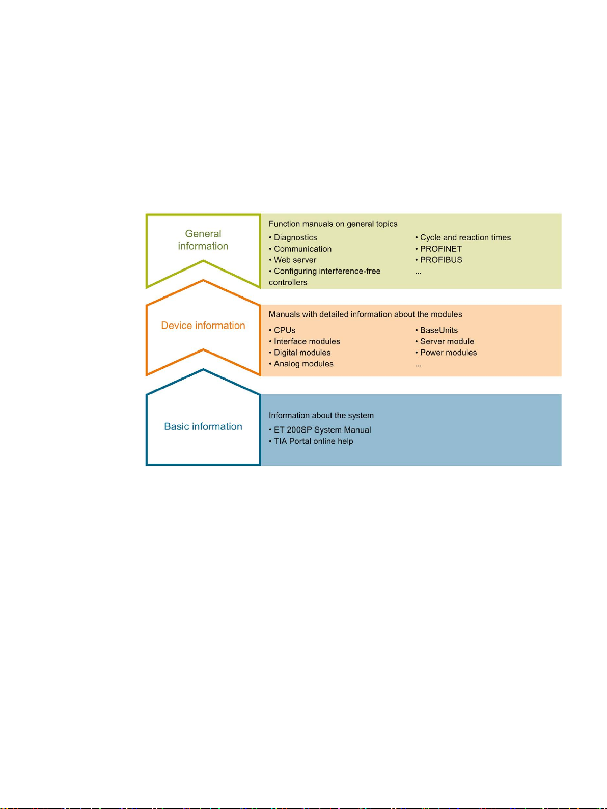
1 ET 200SP Documentation Guide............................................................................................................. 7
2 Product overview .................................................................................................................................... 9
2.1 Properties..................................................................................................................................9
2.2 Functions ................................................................................................................................13
2.2.1 PROFIenergy ..........................................................................................................................23
2.2.2 Configuration control (option handling)...................................................................................24
2.2.3 Use of fail-safe modules .........................................................................................................24
2.2.4 Multi Hot Swap........................................................................................................................25
3 Wiring ................................................................................................................................................... 26
3.1 Pin assignment .......................................................................................................................26
3.2 Block diagram .........................................................................................................................30
4 Parameters/address space ................................................................................................................... 31
4.1 Parameters .............................................................................................................................31
4.2 Explanation of parameters ......................................................................................................31
4.2.1 Enable configuration control ...................................................................................................31
4.3 Substitute value behavior .......................................................................................................32
4.4 Status of the supply voltage L+ of the I/O modules................................................................33
5 Interrupts, error messages, diagnostics and system alarms................................................................... 34
5.1 Status and error displays ........................................................................................................34
5.2 Interrupts.................................................................................................................................38
5.2.1 Triggering of a diagnostics interrupt .......................................................................................39
5.2.2 Triggering a hardware interrupt ..............................................................................................39
5.2.3 Triggering of a remove/insert module interrupt.......................................................................39
5.3 Alarms.....................................................................................................................................40
5.3.1 Diagnostics alarms..................................................................................................................40
5.3.2 Maintenance events................................................................................................................41
5.3.3 Channel diagnostics................................................................................................................42
5.3.4 Invalid configuration states of the ET 200SP on PROFINET IO ............................................45
5.3.5 Failure of supply voltage L+ at BaseUnit BU...D ....................................................................45
5.3.6 STOP of the IO controller and recovery of the IO device .......................................................46
6 Compatibility ......................................................................................................................................... 47
6.1 Compatibility of modules.........................................................................................................47
7 Technical specifications ........................................................................................................................ 51
A Dimension drawing ............................................................................................................................... 57