Prosense SCU-2501 User manual
~ WARNING ~
This device is designed for connection to hazardous electric voltages. Ignoring this warning can result
in severe personal injury or mechanical damage. To avoid the risk of electric shock and fire, the safety
instructions of this guide must be observed and the guidelines followed. The specifications must not be
exceeded, and the device must only be applied as described in the following. Prior to the commissioning
of the device, this installation guide must be examined carefully. Only qualified personnel (technicians)
should install this device. If the equipment is used in a manner not specified by the manufacturer, the
protection provided by the equipment may be impaired.
Until the device is mounted, do not connect hazardous voltages to the device. The following operations
should only be carried out on a disconnected device and under ESD safe conditions: General mounting,
connection and disconnection of wires.
Do not open the front plate of the device as this will cause damage to the connector for the
display / programming front SCU-PDM2. This device contains no DIP-switches or jumpers. Units must
be mounted on a DIN rail according to DIN 60715
SAFETY INSTRUCTIONS
Receipt and unpacking
Unpack the device without damaging it. The packing should always follow the device until it has been perma-
nently mounted. Check at the receipt of the device to ensure the type corresponds to the one ordered.
Environment
Avoid direct sunlight, dust, high temperatures, mechanical vibrations and shock, as well as rain and heavy
moisture. If necessary, heating in excess of the stated limits for ambient temperatures should be avoided by
way of ventilation. All devices can be used for Measurement / Overvoltage Category II and Pollution Degree
2. The module is designed to operate safely at an altitude of 2000m or less.
Mounting
Mounting and connection of the device should comply with national legislation for mounting of electric
materials, i.e. wire cross section, protective fuse, and location. Descriptions of input / output and supply
connections are shown in this installation guide and on the side label. The following apply to hazardous
voltage-connected devices:
The max. protective fuse is 10A. A power switch shall be easily accessible and close to the device. The power
switch shall be marked as the disconnecting unit for the device.
UL installation requirements
Use 60/75°C copper conductors only.
For use only in pollution degree 2 or better.
Max. ambient temperature ................................................. 60°C (140°F)
Wire size ............................................................................ AWG 26-14
UL file number, SCU-2501, SCU-2502 & SCU-2503....... E197592
The device is an Open Type Listed Process Control Equipment. To prevent injury resulting from accessibility
to live parts the equipment must be installed in an enclosure.
Calibration and adjustment
During calibration and adjustment, the measuring and connection of external voltages must be carried out
according to the specifications of this installation guide. The technician must use tools and instruments that
are safe to use.
Cleaning
When disconnected, the device may be cleaned with a cloth moistened with distilled water.
Technical Specifications
Copyright 2022, Automationdirect.com®
Incorporated All Rights Reserved
3505 HUTCHINSON ROAD
CUMMING, GA 30040-5860
Quick Start Guide
Quick Start Guide
Quick Start Guid
eQuick Start Guide
Quick Start Guid
e
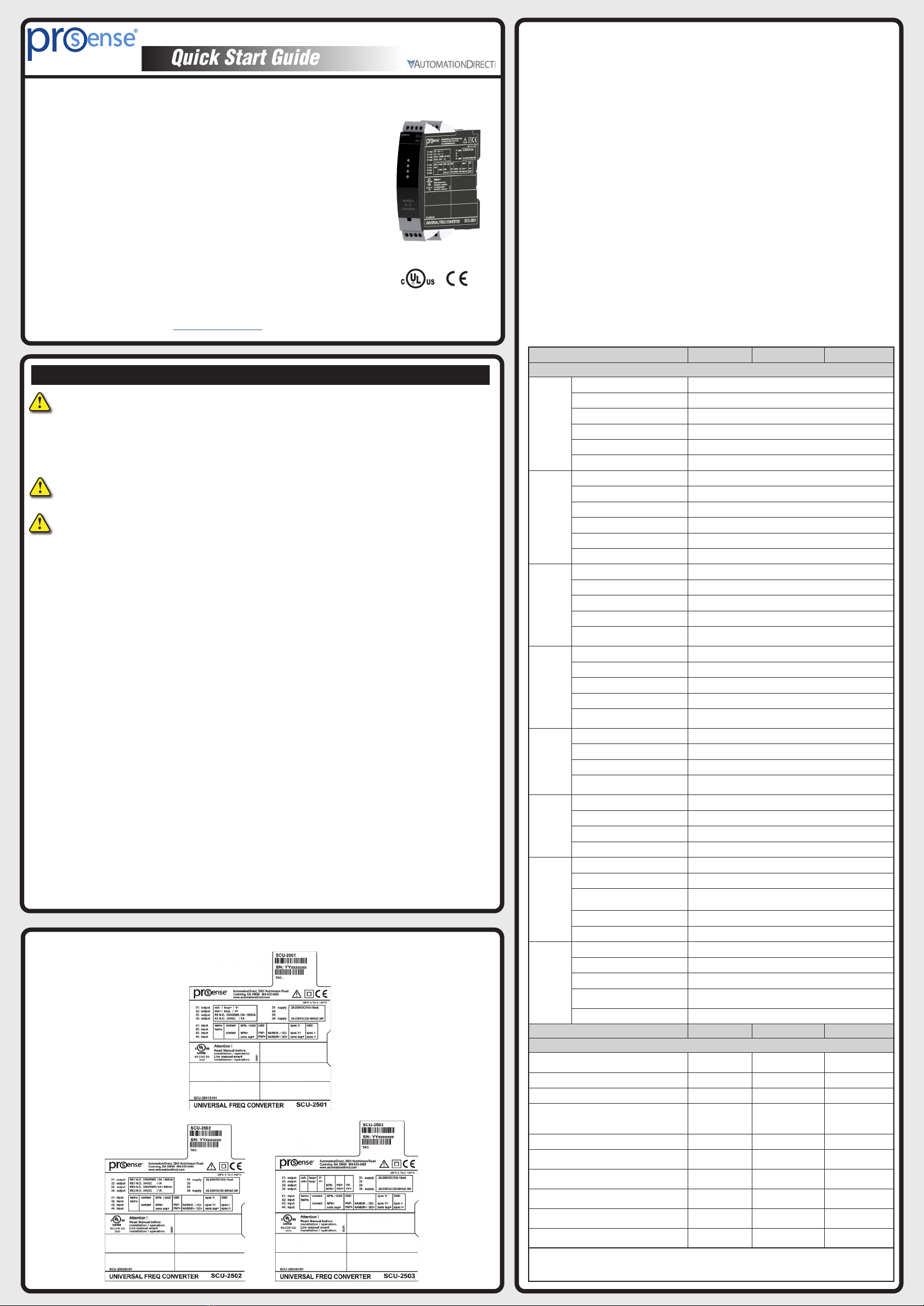
Universal Signal Conditioners
ProSense Universal Transmitter Signal Conditioner models SCU-2501,
SCU-2502 and SCU-2503 are single input devices that accept PNP, NPN,
TTL, NAMUR, and custom special trigger current or voltage level frequency.
The SCU-2501 and SCU-2502 models support relay output with the
SCU-2502 having two independently triggered relay outputs. The SCU-2501
and SCU-2503 provide a mA (sourcing or sinking) or voltage output. The
SCU-2503 is the only unit with a frequency output allowing for frequency/
frequency conversion. They feature a plastic slim-line housing, integral 35mm
DIN rail mounting adapter, and removable screw terminals. The detachable
SCU-PDM2 programming / display module (purchased separately) is required
for unit configuration. The programming / display module may remain affixed
for operational display of input and output values.
Models:
SCU-2501 - Universal Frequency Transmitter with Analog and
Relay Outputs
SCU-2502 - Universal Frequency Transmitter with (2) Relay
Outputs
SCU-2503 - Universal Frequency Transmitter with Analog and
Frequency Outputs
Operating temperature .............................. -20°C to +60°C (-4°F to 140°F)
Storage temperature .................................. -20°C to +85°C (-4°F to 185°F)
Supply voltage............................................ 21.6...253 VAC or 19.2...300 VDC
Max. required power:
SCU-2501/2/3.................................................. ≤2.6 W
Max. power dissipation:
SCU-2501/2/3.................................................. ≤2.1 W
Fuse ........................................................... 400mA SB / 250VAC
Isolation voltage, test / operation................ 2.3 kVAC / 250VAC
(reinforced isolation)
EMC immunity influence........................... < ±0.5% of span
Extended EMC immunity:
NAMUR NE 21, A criterion, burst.......... < ±1% of span
Relative humidity........................................ < 95% RH (non-cond.)
Dimensions (HxWxD) ............................... 109 x 23.5 x 104 mm
Dimensions (HxWxD) w/ SCU-PDM2...... 109 x 23.5 x 116 mm
Protection degree ........................................ IP20
Approvals
UL, Standard for Safety .............................. UL 508/C22.2 No. 14
Observed authority requirements:
EMC ........................................................... 2014/30/EU
LVD ............................................................ 2014/35/EU
RoHS 2........................................................ 2011/65/EU
Model SCU-2501 SCU-2502 SCU-2503
Input
Frequency
input
Frequency Range 0.001 Hz to 100 kHz
Time range, time function 10 µs to 999.9 s
Max. frequency, with input filter ON 75Hz
Min. pulse width with input filter ON 8ms
Min. pulse width with input filter OFF 4µs
Response time (0...90%, 100...10%) < 30ms
NAMUR input
Trig-level LOW ≤1.2 mA
Trig-level HIGH ≥2.1 mA
Input impedance 1 kΩ|| < 220pF
Breakage detection ≤0.1 mA
Short-circuit detection ≥6.9 mA
Sensor supply - pin 44, fixed 8.3 V
Tacho input
Trig-level LOW ≤-50 mV
Trig-level HIGH ≥+50 mV
Input impedance 100 kΩ|| < 220 pF
Max. input voltage 80VAC pp
Sensor supply - pin 44,
programmable 5...17 V / 23mA
NPN / PNP
input
Trig-level LOW ≤4.0 V
Trig-level HIGH ≥7.0 V
Input impedance 3.48 kΩ|| < 220 pF
Trigger edge NPN = Neg. edge, PNP = Pos. edge.
Sensor supply - pin 44,
programmable 5...17 V / 23mA
TTL input
Trig-level LOW ≤0.8 V
Trig-level HIGH ≥2.0 V
Input impedance ≥100 kΩ|| < 220 pF
Sensor supply - pin 44,
programmable 5...17 V / 23mA
S0 input
Trig-level LOW ≤2.2 mA
Trig-level HIGH ≥9.0 mA
Input impedance 758 Ω|| < 220 pF
Sensor supply - pin 44, fixed. 17V
Special
voltage input
User-programmable trig-levels -0.05...6.50 V
*Hysteresis, min 50 mV
Input impedance, programmable: High Z: ≥100 kΩ|| < 220 pF
Pull up/down; 3.48 kΩ|| < 220 pF
Programmable sensor supply - pin 44 5...17 V / 23 mA
Max. input voltage 17V
Special
current input
User-programmable trig-levels. 0.0...10.0 mA
*Hysteresis, min 0.2 mA
Input impedance 1 kΩ|| < 220 pF
Sensor supply - pin 44,
programmable 5...17 V / 23 mA
Max. input current 17mA
Model SCU-2501 SCU-2502 SCU-2503
Output
Current output 0...20, 4...20, S4-20,
±10 mA, ±20 mA ---------- 0...20, 4...20, S4-20,
±10 mA, ±20 mA
Load (max.), current output ≤600 Ω---------- ≤600 Ω
Current limit ≤28 mA ---------- ≤28 mA
Voltage output 0…5, 1…5, 0...10,
2…10, ±5, ±10 VDC ---------- 0…5, 1…5, 0...10,
2…10, ±5, ±10 VDC
Load (min.), voltage output ≥2 kΩ---------- ≥2 kΩ
Relay output SPST, AC: 250 VAC/
VDC, 2A, 500VA
2 x SPST, AC: 250
VAC/VDC, 2A, 500VA ----------
Frequency output ---------- ---------- 0.001 Hz...100kHz
PNP output ---------- ---------- 24VDC at 30mA
max
NPN output ---------- ---------- 30VDC at 130mA
max
Push-Pull output ---------- ---------- 5...24VDC
* For low signal levels with input trigger level hysteresis below 100 mV / 0.1 mA it is
recommended to use shielded cables with correct grounding, to avoid false triggering due to
induced EMC.
Side Label
Note: Additional specifications available at www.AutomationDirect.com

Installation:
This installation guide for technical personnel covers the following products:
SCU-2501 SCU-2502 SCU-2503
SCU-PDM2
Mounting SCU-PDM2:
1. Insert the tabs of the SCU-PDM2 into the holes at the top of the device.
2. Swing the SCU-PDM2 down until it snaps into place.
Removing the SCU-PDM2:
3. Push the release button on the bottom of the SCU-PDM2 and swing out and up.
4. With the SCU-PDM2 hinged up, remove it from the holes at the top of the device.
Mounting on DIN rail:
Place top notch of module onto DIN rail and then press lower portion onto DIN rail
until it snaps in place.
Removing from DIN rail:
Remember to remove the connectors with hazardous voltages. Detach the device from
DIN rail by lifting the bottom lock.
Wiring:
Max. wire size 1 x 2.5 mm2stranded wire. Screw terminal torque 0.5 Nm.
Error Messages and Troubleshooting
Scrolling Error Message Indication Text Condition Action
Process and application errors
Input error IN.ER - flashing display Input out of configured input limits Check input signal value and configured
input limits
Input underrange IN.LO Input below low cut-off Check input signal source
Input overrange IN.HI Input above valid measurement range Check input signal source
Display out of range -1999 or 9999 Display saturation Check configuration and input values
Analog output error AO.ER Error in analog output current (S4-20 mA
output only)
Check wiring of analog output and recycle
power *
Sensor supply overloaded SE.OL Sensor supply overload condition
detected Check sensor supply specifications
Sensor short circuit SE.SH Sensor short circuit condition Check sensor for short circuit
Sensor wire break SE.BR Sensor open loop / broken wire
condition Check sensor for open loop / broken wire
Device errors
No communication between device and the
SCU-PDM2 communication interface NO.CO No communication (SCU-PDM2 <->
device)
Reattach the SCU-PDM2 communication
interface to the product. If attached,
disconnect and reattach
Configuration error CO.ER Invalid configuration downloaded to
module
Step through menu to create valid
configuration **
Invalid configuration type or version TY.ER Configuration read from the SCU-PDM2
has invalid type or rev. no.
Save correct device type and revision
configuration to the SCU-PDM2
communication interface **
Analog output supply error AO.SU Analog output supply error Verify output configuration and output
connection *
RAM error RA.ER Internal RAM error Contact AutomationDirect *
A/D converter error AD.ER Internal A/D converter error Contact AutomationDirect *
Internal flash error IF.ER Internal flash error Contact AutomationDirect *
Frequency input error FI.ER Internal frequency circuit error Contact AutomationDirect *
EEPROM Error EE.ER Internal EEPROM error Contact AutomationDirect *
Storing of configuration failed - previous
configuration used CO. WARN Writing configuration to internal device
memory failed.
Device configuration reverts to last known
valid configuration. Cycle through menu
to retry writing new configuration.
! All error indications in the display flash once per second. The help text explains the error. If the error is an input loop
error, the display backlight flashes as well - this is acknowledged (stopped) by pushing the 3 button.
* Error is acknowledged by either stepping through the basic setup, or by resetting the device power. Some types of
errors can only be acknowledged by resetting the device power.
** Error is acknowledged by stepping through the basic setup.
Configuring a new unit
• Mount the unit on a 35mm DIN rail and connect supply, input and output wires to the appropriate
terminals based on the connection diagrams in this Quick Start Guide.
• Snap the SCU-PDM2 Programming Module on the front of the unit.
• Power up the unit.
• The unit should display the configuration menu similar to the figure below. If not, press ;once.
• Press ;to begin configuration. Press .or ,to scroll through options on each step. Press ;
to confirm an option and move to the next step.
• Press and hold ;to step backwards through the configuration menu.
Note: If no sensor is connected to the input terminals, SE.BR will flash in the
display when the unit is powered up. Press ;once to acknowledge the
error and then press ;again to display the first screen of the menu as
shown above.
Notes

41 42 43 44
31 32 33 34
41 4342 44
41 4342 44
Tx
41 42 44
43 41 4342 44
41 4342 44
+-
41 4342 44 41 42 44
43 41 4342 44
+
Inputs:
Supply
Special current Special voltage Tacho
PNP NPN Contact (NPN)
S0 TTLNAMUR
S0 TTL
+ supply 5...17 V+ supply 5...17 V
+ supply 5...17 V+ supply 5...17 V
+ supply+supply
+ supply 8.3 V+supply 17 V
Wiring Diagrams
SCU-2501
21 2322 2421 2322 24
+
-V
(±)
R2
21 22 23 24
+
-mA
(±)
21 2322 24
+mA
-
+mA
-
SCU-2502
21 2322 24
R1 R2
21 2322 2421 2322 24
+
-V
(±)
21 22 23 24
+
-mA
(±)
21 2322 24
SCU-2503
+
-
21 22 23 24 21 2322 24
Relays
Outputs:
Relay
2-wire transmitter
(Passive output)
Current
(Active output)
2-wire transmitter
(Passive output)
Frequency
(Push / pull)
Current
(Active output)
Frequency
(NPN output)
Frequency
(PNP output)
Rload
Rload
Application Example - Frequency Input to
Relay Output (SCU-2502)
A flow sensor with 12VDC NPN output needs to be connected to two LEDs as a
low and high flow alarm indication in a panel. The sensor measures fluid flow in
0.1 gallons per pulse. When using the SCU-2502, low and high alarms will be set at
5GPM and 55GPM respectively with a 3GPM hysteresis and 5 second on delay set for
each alarm. In the event of a sensor error, both relays will hold in their current state
when the error occured. Relay switching will work as follows:
058 52 55 60GPM
Relay 1 (Low flow LED) Relay 2 (High flow LED)
• In the configuration menu press .or ,until NPN is displayed IN.TYPE. Press
;.
• Set sensor supply voltage. Press .or ,until 12.0 is displayed for S.SUP. Press ;.
• Select input units. Press .or ,until Hz is displayed for IN.
Press ;.
• Select input low value. Press .or ,until 0is displayed for IN.LO. Press ;.
• Select high value. Press .or ,until 10 is displayed for IN.HI. Press ;.
• Select input filter to off. Press .or ,until NO is displayed for FILTER. Press
;.
• Select scaled units. Press .or ,until GAL/MIN is displayed for UNIT. Press ;.
• Select decimal point location. Press .or ,until 111.1 is displayed for DEC.P. Press
;.
• Set display value for minimum input. Press .or ,until 0.0 is displayed for DISP.
LO. Press ;.
• Set display value for maximum input. Press .or ,until 60.0 is displayed for
DISP.HI. Press ;.
• Set display response time. Press .or ,until 0is displayed for DISP.RP. Press ;.
Relay Configuration
• Select the relay unit type. Press .or ,until DISP is displayed for REL.UNI. Press ;.
• Select relay 1 function. Press .or ,until SETP is displayed for R1.FUNC. Press ;.
• Select relay contact type. Press .or ,until N.O. is displayed for R1.CONT. Press ;.
• Set relay setpoint. Press .or ,until 5.0 is displayed for R1.SETP.
Press ;.
• Select relay activation decreasing mode. Press .or ,until DECR is displayed for ACT.DIR. Press
;.
• Set relay hysteresis. Press .or ,until 3.0 is displayed for R1.HYST.
Press ;.
• Set relay on delay in seconds. Press .or ,until 5is displayed for ON.DEL. Press ;.
• Set relay off delay in seconds. Press .or ,until 0is displayed for OFF.DEL. Press ;.
• Select relay 2 function. Press .or ,until SETP is displayed for R2.FUNC. Press ;.
• Select contact type. Press .or ,until N.O. is displayed for R2.CONT.
Press ;.
• Set relay setpoint. Press .or ,until 55 is displayed for R2.SETP.
Press ;.
• Select relay activation increasing mode. Press .or ,until INCR is displayed for ACT.DIR. Press ;.
• Set relay hysteresis. Press .or ,until 3.0 is displayed for R2.HYST.
Press ;.
• Set relay on delay in seconds. Press .or ,until 5is displayed for ON.DEL. Press ;.
• Set relay off delay in seconds. Press .or ,until 0is displayed for OFF.DEL. Press ;.
• Set input limit low to off. Press .or ,until NO is displayed for ILIM.L. Press
;.
• Set input limit high to off. Press .or ,until NO is displayed for ILIM.H. Press
;.
• Set power on delay time. Press .or ,until 0is displayed for POW.DEL. Press
;.
• Wait while the settings are stored and the unit switches to run mode.
Once the unit has been configured, the relay setpoints can be adjusted very quickly. Press
.to adjust RELAY1 and ,to adjust RELAY2. Adjust the setpoint up or down and
then press ;to save the setting and exit the menu. Pressing .and ,simultane-
ously will change the active relay’s state.
Application Example - Convert a PNP 24V Pulsed Signal to
Analog 0-10VDC (SCU-2501)
A 24VDC pulsed signal from a senor is converted to a linear 0-10VDC analog
output.
• In the configuration menu press .or ,until PNP is displayed IN.TYPE.
Press ;.
• Select sensor supply voltage. Press .or ,until 10.0 is displayed for S.SUP.
Press ;.
• Select input units. Press .or ,until Hz is displayed for IN. Press ;.
• Set input low value. Press .or ,until 0is displayed for IN.LO. Press ;.
• Set input high value. Press .or ,until 25.00 kHz is displayed for IN.HI.
Press ;.
• Set scaled units. Press .or ,until %is displayed for UNIT. Press ;.
• Select decimal point location. Press .or ,until 111.1 is displayed for DEC.P.
Press ;.
• Set display value for minimum input. Press .or ,until 0.0 is displayed for
DISP.LO. Press ;.
• Set display value for maximum input. Press .or ,until 100.0 is displayed
for DISP.HI. Press ;.
• Set display response time. Press .or ,until 0is displayed for DISP.RP. Press
;.
• Set output type. Press .or ,until VOLT is displayed for OUT.TY. Press ;.
• Set output voltage range. Press .or ,until 0-10 is displayed for O.RANGE.
Press ;.
• Set relay units. Press .or ,until DISP is displayed for REL.UNI. Press ;.
• Set relay to off. Press .or ,until OFF is displayed for R1.FUNC. Press ;.
• Set input limit low to off. Press .or ,until NO is displayed for ILIM.L. Press
;.
• Set input limit high to off. Press .or ,until NO is displayed for ILIM.H.
Press ;.
• Set output response time. Press .or ,until 0.0 is displayed for OUT.RSP.
Press ;.
• Set power on delay time. Press .or ,until 0is displayed for POW.DEL. Press
;.
• Wait while the settings are stored and the unit switches to run mode.

Application Example - Convert a TTL Frequency Input to
a PNP Output and Scaling the Frequency
A TTL output sensor, connected to a SCU-2503, delivers a 5VDC frequency
output scaled up from 0-1kHz to 0-100kHz.
• Set sensor supply voltage. Press .or ,until 5.0 is displayed for S.SUP. Press
;.
• Select input units. Press .or ,until Hz is displayed for IN. Press ;.
• Set input low value. Press .or ,until 0is displayed for IN.LO. Press ;.
• Set input high value. Press .or ,until 1.000 is displayed for IN.HI. Press
;.
• Set scaled units. Press .or ,until kHz is displayed for UNIT. Press ;.
• Select decimal point location. Press .or ,until 111.1 is displayed for DEC.P.
Press ;.
• Set display value for minimum input. Press .or ,until 0.0 is displayed for
DISP.LO. Press ;.
• Set display value for maximum input. Press .or ,until 100.0 is displayed
for DISP.HI. Press ;.
• Set display response time. Press .or ,until 0is displayed for DISP.RP.
Press ;.
• Set output type. Press .or ,until FREQ is displayed for OUT.TY. Press
;.
• Set output voltage range. Press .or ,until Hz is displayed for OU.UN. Press
;.
• Set output low frequency. Press .or ,until 0is displayed for OUT.LO. Press
;.
• Set output low cut off frequency. Press .or ,until 0is displayed for
LO.CUT. Press ;.
• Set output contact type. Press .or ,until 0is displayed for CONT.TY. Press
;.
• Set input limit low to off. Press .or ,until NO is displayed for ILIM.L.
Press ;.
• Set input limit high to off. Press .or ,until NO is displayed for ILIM.H.
Press ;.
• Set output response time. Press .or ,until 0.0 is displayed for OUT.RSP.
Press ;.
• Set power on delay time. Press .or ,until 0is displayed for POW.DEL.
Press ;.
• Wait while the settings are stored and the unit switches to run mode.
Copyright 2022, Automationdirect.com Incorporated/All Rights
Reserved Worldwide
Several useful functions are in the Advanced Settings Menu. To get to the
Advanced Settings Menu, Press .or ,until YES is displayed for the first
screen of the configuration menu that looks like this:
The configuration of the SCU-250x can be saved into the SCU-PDM2. The
SCU-PDM2 can then be moved to another unit (must be the same part number)
and the configuration loaded into the new unit.
• Enter Advanced Settings menu and then press .or ,until MEM is
displayed for SETUP. Press ;.
• To save the configuration into the SCU-PDM2. Press .or ,until SAVE is
displayed for MEMORY. Press ;.
• To load the configuration from the SCU-PDM2 into the SCU250x. Press .or
,until LOAD is displayed for MEMORY. Press ;.
Password Protection allows the user to create a 4-digit password
(0000-9999) to prevent tampering with configuration settings if the
SCU-PDM2 is left mounted to the front of the signal conditioner.
• Enter Advanced Settings menu and then press .or ,until PASS is
displayed for SETUP. Press ;.
• To enable password protection. Press .or ,until YES is displayed for
EN.PASS. Press ;.
• To set a password. Press .or ,until the desired code is displayed for NEW.
PAS. Press ;.
Advanced Operations
Notes
Additional Help and Support
• For product support, specifications, installation and
troubleshooting, a Hardware User Manual can be downloaded from the On-line Documentation area of the
AutomationDirect web site.
• For additional technical support and questions, call out
Technical Support team @ 1-800-633-0405 or 770-844-4200
This manual suits for next models
2
Other Prosense Test Equipment manuals

Popular Test Equipment manuals by other brands


Redtech
Redtech TRAILERteck T05 user manual

Venmar
Venmar AVS Constructo 1.0 HRV user guide

Test Instrument Solutions
Test Instrument Solutions SafetyPAT operating manual

Hanna Instruments
Hanna Instruments HI 38078 instruction manual

Kistler
Kistler 5495C Series instruction manual

Waygate Technologies
Waygate Technologies DM5E Basic quick start guide

StoneL
StoneL DeviceNet CK464002A manual

Seica
Seica RAPID 220 Site preparation guide

Kingfisher
Kingfisher KI7400 Series Training manual

Kurth Electronic
Kurth Electronic CCTS-03 operating manual

SMART
SMART KANAAD SBT XTREME 3G Series user manual

Agilent Technologies
Agilent Technologies BERT Serial Getting started