Prosense SCU-2200 User manual

~ WARNING ~
This device is designed for connection to hazardous electric voltages. Ignoring this warning can result
in severe personal injury or mechanical damage. To avoid the risk of electric shock and fire, the safety
instructions of this guide must be observed and the guidelines followed. The specifications must not be
exceeded, and the device must only be applied as described in the following. Prior to the commissioning
of the device, this installation guide must be examined carefully. Only qualified personnel (technicians)
should install this device. If the equipment is used in a manner not specified by the manufacturer, the
protection provided by the equipment may be impaired.
Until the device is mounted, do not connect hazardous voltages to the device. The following operations
should only be carried out on a disconnected device and under ESD safe conditions: General mounting,
connection and disconnection of wires.
Do not open the front plate of the device as this will cause damage to the connector for the
display / programming front SCU-PDM2. This device contains no DIP-switches or jumpers. Units
must be mounted on a DIN rail according to DIN 60715
SAFETY INSTRUCTIONS
Receipt and unpacking
Unpack the device without damaging it. The packing should always follow the device until it has been perma-
nently mounted. Check at the receipt of the device to ensure the type corresponds to the one ordered.
Environment
Avoid direct sunlight, dust, high temperatures, mechanical vibrations and shock, as well as rain and heavy
moisture. If necessary, heating in excess of the stated limits for ambient temperatures should be avoided by
way of ventilation. All devices can be used for Measurement / Overvoltage Category II and Pollution Degree
2. The module is designed to operate safely at an altitude of 2000m or less.
Mounting
Mounting and connection of the device should comply with national legislation for mounting of electric
materials, i.e. wire cross section, protective fuse, and location. Descriptions of input / output and supply
connections are shown in this installation guide and on the side label. The following apply to hazardous
voltage-connected devices:
The max. protective fuse is 10A. A power switch shall be easily accessible and close to the device. The power
switch shall be marked as the disconnecting unit for the device.
UL installation requirements
Use 60/75°C copper conductors only.
For use only in pollution degree 2 or better.
Max. ambient temperature ................................................. 60°C (140°F)
Wire size ............................................................................ AWG 26-14
UL file number, SCU-2200................................................ E191072
The device is an Open Type Listed Process Control Equipment. To prevent injury resulting from accessibility
to live parts the equipment must be installed in an enclosure.
Calibration and adjustment
During calibration and adjustment, the measuring and connection of external voltages must be carried out
according to the specifications of this installation guide. The technician must use tools and instruments that
are safe to use.
Cleaning
When disconnected, the device may be cleaned with a cloth moistened with distilled water.
Technical Specifications
Copyright 2022, Automationdirect.com®
Incorporated All Rights Reserved
3505 HUTCHINSON ROAD
CUMMING, GA 30040-5860
Quick Start Guide
Quick Start Guide
Quick Start Guid
eQuick Start Guide
Quick Start Guid
e
Universal Signal Conditioners
ProSense Universal Analog to Frequency (I/f) Converter model
SCU-2200 is a single input device that accepts milliampere, voltage,
RTD, thermocouple or potentiometer inputs and provides a select-
able single frequency output. It features a plastic slim-line housing,
integral 35mm DIN rail mounting adapter, and removable screw
terminals. The detachable SCU-PDM2 programming / display
module (purchased separately) is required for unit configuration. The
programming / display module may remain affixed for operational
display of input and output values.
Models:
SCU-2200 - Universal Analog to Frequency (l/f) Converter
Operating temperature .............................. -20°C to +60°C (-4°F to 140°F)
Storage temperature .................................. -20°C to +85°C (-4°F to 185°F)
Supply voltage........ ................................... 21.6...253 VAC or 19.2...300 VDC
Max. required power................................... ≤2.5 W
Max. power dissipation............................... ≤2.0 W
Fuse ........................................................... 400mA SB / 250VAC
Isolation voltage, test / operation................ 2.3 kVAC / 250VAC
(reinforced isolation)
EMC immunity influence........................... < ±0.5% of span
Extended EMC immunity:
NAMUR NE 21, A criterion, burst.......... < ±1% of span
Conducted emission.................................... Class A 150kHz - 10MHz
Relative humidity........................................ < 95% RH (non-cond.)
Dimensions (HxWxD) ............................... 109 x 23.5 x 104 mm
Dimensions (HxWxD) w/ SCU-PDM2.....109 x 23.5 x 116mm/131mm
Protection degree ........................................ IP20
Approvals
UL, Standard for Safety .............................. UL 508/C22.2 No. 14
Observed authority requirements:
EMC ........................................................... 2014/30/EU
LVD ............................................................ 2014/35/EU
RoHS 2........................................................ 2011/65/EU
Model SCU-2200
Input
Input for RTD types Pt10, Pt20, Pt50, Pt100, Pt200, PT250, Pt300, Pt400,
Pt500, Pt1000, Ni50, Ni100, Ni120, Ni1000
Input for TC types B, E, J, K, L, N, R, S, T, U, W3, W5, LR
Current input ranges 0...20, 4...20 mA
Current input resistance Nom. 20 Ω+ PTC 50 Ω
Input voltage drop, nom. 1.4 V @ 20 mA
Voltage input ranges 0/0.2...1, 0/0.5...2.5, 0/1...5, 0/2...10 VDC
Voltage input resistance Nom. 10 MΩ
Output
Frequency output
Frequency range 0...25000 Hz
Min. frequency (span) 0 Hz
Duty cycle (0...25000 Hz) 50% or
Programmable pulse time (f ≤500 Hz) 1...1000 ms (max. 90% duty cycle)
PNP output
Iout max 30mA
Vout 24VDC ± 10%
Cout 10nF
Rout typ. 20Ω
Electromechanical counter 24V / 135mA / 20ms / ≤10Hz
NPN output
Isink max 150mA
Isink/source peak 300mA
External voltage (terminal 23) max 55VDC
Cout 10nF
Rout typ 10Ω
TTL output
Isink max 15mA
Isink/source peak 100mA
Vout 5 V ±5%
Cout 10nF
Rout typ 55Ω
Sensor error detection Programmable 0...26250 Hz
Installation:
This installation guide for technical personnel covers the following products:
SCU-2200
SCU-PDM2
Mounting SCU-PDM2:
1. Insert the tabs of the SCU-PDM2 into the holes at the top of the device.
2. Swing the SCU-PDM2 down until it snaps into place.
Removing the SCU-PDM2:
3. Push the release button on the bottom of the SCU-PDM2 and swing out and up.
4. With the SCU-PDM2 hinged up, remove it from the holes at the top of the device.
Mounting on DIN rail:
Place top notch of module onto DIN rail and then press lower portion onto DIN rail
until it snaps in place.
Removing from DIN rail:
Remember to remove the connectors with hazardous voltages. Detach the device from
DIN rail by lifting the bottom lock.
Wiring:
Max. wire size 1 x 2.5 mm2stranded wire. Screw terminal torque 0.5 Nm.
Side Label
Note: Additional specifications available at www.AutomationDirect.com
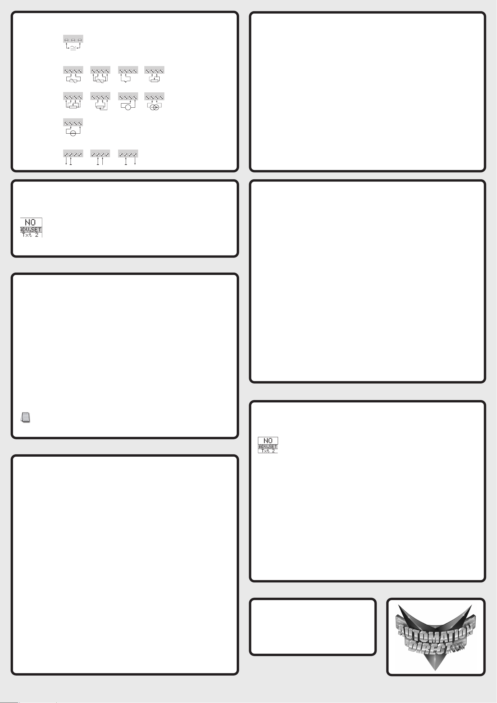
31 32 33
41 42 44
43
42 44
43
41 41 42 44
43
41 42 44
43
+
-
41 42 44
43 41 42 44
43
+
-
41 42 44
43
+
-Tx
41 42 44
43
+
-
41 42 44
43
21 22 24
23 21 22 24
23
21 22 24
23
+
Outputs:
NPNTTL PNP
TC Resistance, 2-wireRTD, 3- / 4-wireRTD, 2-wire
Inputs:
Supply
2-wire transmitter Current
Potentiometer
Resistance,
3- / 4-wire
Voltage
Gnd+ 5 V Gnd Gnd + 24 V
Wiring Diagrams
Configuring a new unit
• Mount the unit on a 35mm DIN rail and connect supply, input and output wires to the
appropriate terminals based on the connection diagrams in this Quick Start Guide.
• Snap the SCU-PDM2 Programming Module on the front of the unit.
• Power up the unit.
• The unit should display the configuration menu similar to the figure below. If
not, press ;once.
• Press ;to begin configuration. Press .or ,to scroll through
options on each step. Press ;to confirm an option and move to the next
step.
• Press and hold ;to step backwards through the configuration menu.
Abbreviations used on the SCU-PDM2 display
Note: Help text for each abbreviation will scroll across the SCU-PDM2
FL.CO = flash memory error
CJ.ER = CJC sensor defect
NO.CO = connection error with SCU-PDM2
IN.ER = error levels on input
TY.ER = configuration in SCU-PDM2
doesn’t match this product
ADV.SET = advanced settings
IN TYPE = input type
V.RANGE = voltage range
I.RANGE = current range
CONNEC. = connecting wires
Pt TYPE = Platinum RTD type
Ni TYPE = Nickel RTD type
TC.TYPE = thermocouple type
DEC.P = decimal place location
SE.BR = a sensor wire is not connected
DECR = decreasing
ACT.DIR = action direction
DISP.LO = display range low
DISP.HI = display range high
OU.UN = set Hz or pulse output
f.min = set 0% frequency input
f.max = set 100% frequency input
CUT.OFF = set cut off frequency
O.TYPE = output pulse type
t.PULSE = pulse time in milliseconds
P.min = set 0% pulse
P.max = set 100% pulse
f.ERR = output frequency on input error
RESP = response time in seconds
OUT.ERR = output action on error
OUT.LO = temp for low output
OUT.HI = temp for high output
EN.PASS = enable password
NEW.PAS = new password
CAL.LO = calibrate input low to process value?
CAL.HI = calibrate input high to process value?
USE.CAL = Use process calibration value?
Convert a potentiometer position to a 0-100 percentage frequency signal.
• In the configuration menu Press .or ,until POTM is displayed for IN.TYPE. Press ;.
• Select input units. Press .or ,until %is displayed for UNIT. Press ;.
• Select decimal point location. Press .or ,until 111.1 is displayed for DEC.P. Press ;.
• Set display value for minimum input. Press .or ,until 0.0 is displayed for DISP.LO. Press
;.
• Set display value for maximum input. Press .or ,until 100.0 is displayed for DISP.HI.
Press ;.
• Select output unit. Press .or ,until Hz is displayed for OU.UN. Press ;.
• Select output minimum frequency. Press .or ,until 0is displayed for F.MIN. Press ;.
• Select output maximum frequency. Press .or ,until 10.00 kHZ is displayed for F.MAX.
Press ;.
• Select output cutoff frequency. Press .or ,until 0is displayed for CUT.OFF. Press ;.
• Select no output error frequency. Press .or ,until NO is displayed for OUT.ERR. Press ;.
• Set frequency output response time. Press .or ,until 0.4 is displayed for RESP. Press ;.
• Wait while the settings are stored and the unit switches to run mode.
The SCU-2200 will provide no signal when the potentiometer is turned to zero % and 10kHz at
100%.
Application Example - Potentiometer Input to Frequency Output
Application Example - 10VDC Input from DC Current
Transducer to Frequency Output
Monitoring 10VDC output from a DC current transducer monitoring DC amperage into a
pulse/frequency input on a PLC.
• In the configuration menu press .or ,until VOLT is displayed for IN.TYPE. Press
;.
• Select input range. Press .or ,until ~0-10 is displayed for V.RANGE. Press ;.
• Select input units. Press .or ,until Ais displayed for UNIT. Press ;.
• Select decimal point location. Press .or ,until 111.1 is displayed for DEC.P. Press ;.
• Set display value for minimum input. Press .or ,until 0.0 is displayed for DISP.LO.
Press ;.
• Set display value for maximum input. Press .or ,until 100.0 is displayed for DISP.
HI. Press ;.
• Select output unit. Press .or ,until Hz is displayed for OU.UN. Press ;.
• Select output minimum frequency. Press .or ,until 0is displayed for F.MIN. Press
;.
• Select output maximum frequency. Press .or ,until 3.000 kHz is displayed for
F.MAX. Press ;.
• Select output cutoff frequency. Press .or ,until 0is displayed for CUT.OFF. Press
;.
• Select output error response. Press .or ,until 0.4 is displayed for RESP. Press ;.
• Wait while the settings are stored and the unit switches to run mode.
The SCU-2200 will provide no output at 0A and a 3kHz output at 100A (10V).
• In the configuration menu press .or ,until TEMP is displayed for IN.TYPE. Press ;.
• Select temperature sensor type. Press .or ,until Pt is displayed for SENSOR. Press ;.
• Select RTD type. Press .or ,until 100 is displayed for Pt.TYPE. Press ;.
• Select RTD connection type. Press .or ,until 4W is displayed for CONNEC. Press ;.
• Select temperature unit. Press .or ,until °Cis displayed for UNIT. Press ;.
• Select frequency output. Press .or ,until Hz is displayed for OU.UN. Press ;.
• Select output minimum. Press .or ,until 0is displayed for F.MIN. Press ;.
• Select output maximum. Press .or ,until 5.000 kHz is displayed for F.MAX. Press ;.
• Select output cutoff frequency. Press .or ,until 0is displayed for CUT.OFF. Press ;.
• Select no output error frequency. Press .or ,until NO is displayed for OUT.ERR. Press
;.
• Set frequency output response time. Press .or ,until 1.0 is displayed for RESP. Press ;.
• Select temperature for low frequency output. Press .or ,until 0is displayed for OUT.LO.
Press ;.
• Select temperature for high frequency output. Press .or ,until 100 is displayed for
OUT.HI. Press ;.
• Wait while the settings are stored and the unit switches to run mode.
The SCU-2200 will provide a frequency output that correlates to the temperature sensed by the
RTD from 0 Hz to 5 kHz representing a temperature range of 0 to 100 C.
Application Example - 4-Wire RTD to Frequency Output
Several useful functions are in the Advanced Settings Menu. To get to the Advanced Settings
Menu, Press .or ,until YES is displayed for the first screen of the configuration menu
that looks like this:
The configuration of the SCU-2200 can be saved into the SCU-PDM2. The SCU-PDM2 can
then be moved to another unit (must be the same part number) and the configuration loaded into
the new unit.
• Enter Advanced Settings menu and then press .or ,until MEM is displayed for SETUP.
Press ;.
• To save the configuration into the SCU-PDM2. Press .or ,until SAVE is displayed for
MEMORY. Press ;.
• To load the configuration from the SCU-PDM2 into the SCU-2200. Press .or ,until LOAD
is displayed for MEMORY. Press ;.
Password Protection allows the user to create a 4-digit password
(0000-9999) to prevent tampering with configuration settings if the SCU-PDM2 is left mounted
to the front of the signal conditioner.
• Enter Advanced Settings menu and then press .or ,until PASS is displayed for SETUP.
Press ;.
• To enable password protection. Press .or ,until YES is displayed for EN.PASS. Press ;.
• To set a password. Press .or ,until the desired code is displayed for NEW.PAS. Press ;.
Advanced Operations
Additional Help and Support
• For product support, specifications, installation and
troubleshooting, a Hardware User Manual can be
downloaded from the On-line Documentation area of the
AutomationDirect web site.
• For additional technical support and questions, call out
Technical Support team @ 1-800-633-0405 or 770-844-4200
Copyright 2022, Automationdirect.com Incorporated/All Rights Reserved Worldwide
Other Prosense Test Equipment manuals

Popular Test Equipment manuals by other brands

Imada
Imada DSW Series instruction manual

Bms Bulut Makina
Bms Bulut Makina DIGIROCK-RMC Operation manual

Softing
Softing WireXpert Cat6A+Adapters user manual

Ralston Instruments
Ralston Instruments Nitropack Operation manual

DATREND Systems
DATREND Systems venTest operating manual

HeFei Jinhan Electronic
HeFei Jinhan Electronic JDS2022S introduction


