ProSoft inRax MVI94-GSC-E User manual
MVI94-GSC-E
FLEX Platform
Generic ASCII Comunication Module
July 06, 2009
USER MANUAL

Important Installation Instructions
Power, Input and Output (I/O) wiring must be in accordance with Class I, Division 2 wiring methods, Article 501-4 (b)
of the National Electrical Code, NFPA 70 for installation in the U.S., or as specified in Section 18-1J2 of the Canadian
Electrical Code for installations in Canada, and in accordance with the authority having jurisdiction. The following
warnings must be heeded:
A WARNING - EXPLOSION HAZARD - SUBSTITUTION OF COMPONENTS MAY IMPAIR SUITABILITY FOR
CLASS I, DIV. 2;
B WARNING - EXPLOSION HAZARD - WHEN IN HAZARDOUS LOCATIONS, TURN OFF POWER BEFORE
REPLACING OR WIRING MODULES, and
C WARNING - EXPLOSION HAZARD - DO NOT DISCONNECT EQUIPMENT UNLESS POWER HAS BEEN
SWITCHED OFF OR THE AREA IS KNOWN TO BE NONHAZARDOUS.
D "THIS DEVICE SHALL BE POWERED BY CLASS 2 OUTPUTS ONLY.
MVI (Multi Vendor Interface) Modules
WARNING - EXPLOSION HAZARD - DO NOT DISCONNECT EQUIPMENT UNLESS POWER HAS BEEN
SWITCHED OFF OR THE AREA IS KNOWN TO BE NON-HAZARDOUS.
AVERTISSEMENT - RISQUE D'EXPLOSION - AVANT DE DÉCONNECTER L'EQUIPMENT, COUPER LE
COURANT OU S'ASSURER QUE L'EMPLACEMENT EST DÉSIGNÉ NON DANGEREUX.
CL I Div 2 GPs A, B, C, D
Temp Code T5
II 3 G
Ex nA IIC T5 X
0° C <= Ta <= 60° C
II - Equipment intended for above ground use (not for use in mines).
3 - Category 3 equipment, investigated for normal operation only.
G - Equipment protected against explosive gasses.
Warnings
North America Warnings
A Warning - Explosion Hazard - Substitution of components may impair suitability for Class I, Division 2.
B Warning - Explosion Hazard - When in Hazardous Locations, turn off power before replacing or rewiring
modules.
Warning - Explosion Hazard - Do not disconnect equipment unless power has been switched off or the area is
known to be nonhazardous.
C Suitable for use in Class I, division 2 Groups A, B, C and D Hazardous Locations or Non-Hazardous Locations.
Electrical Ratings
Backplane Current Load: 800 mA @ 5 V DC; 3mA @ 24V DC
Operating Temperature: 0 to 60°C (32 to 140°F)
Storage Temperature: -40 to 85°C (-40 to 185°F)
Shock: 30g Operational; 50g non-operational; Vibration: 5 g from 10 to 150 Hz
Relative Humidity 5% to 95% (non-condensing)
All phase conductor sizes must be at least 1.3 mm(squared) and all earth ground conductors must be at least
4mm(squared).

Markings
cUL C22.2 No. 213-1987
Your Feedback Please
We always want you to feel that you made the right decision to use our products. If you have suggestions, comments,
compliments or complaints about the product, documentation or support, please write or call us.
ProSoft Technology
5201 Truxtun Ave., 3rd Floor
Bakersfield, CA 93309
+1 (661) 716-5100
+1 (661) 716-5101 (Fax)
www.prosoft-technology.com
Copyright © ProSoft Technology, Inc. 2009. All Rights Reserved.
MVI94-GSC-E User Manual
July 06, 2009
ProSoft Technology ®, ProLinx ®, inRAx ®, ProTalk®, and RadioLinx ® are Registered Trademarks of ProSoft
Technology, Inc. All other brand or product names are or may be trademarks of, and are used to identify products
and services of, their respective owners.
ProSoft Technology® Product Documentation
In an effort to conserve paper, ProSoft Technology no longer includes printed manuals with our product shipments.
User Manuals, Datasheets, Sample Ladder Files, and Configuration Files are provided on the enclosed CD, and are
available at no charge from our web site: www.prosoft-technology.com
Printed documentation is available for purchase. Contact ProSoft Technology for pricing and availability.
Asia Pacific: +603.7724.2080
Europe, Middle East, Africa: +33 (0) 5.3436.87.20
Latin America: +1.281.298.9109
North America: +1.661.716.5100


Contents MVI94-GSC-E ♦FLEX Platform
User Manual Generic ASCII Comunication Module
ProSoft Technology, Inc. Page 5 of 60
July 6, 2009
Contents
Important Installation Instructions.......................................................................................................2
MVI (Multi Vendor Interface) Modules ................................................................................................2
Warnings.............................................................................................................................................2
Your Feedback Please........................................................................................................................3
ProSoft Technology® Product Documentation...................................................................................3
1Hardware Installation 7
1.1 Verify Package Contents...........................................................................................7
1.2 Mounting the MVI 94 Flex I/O Base..........................................................................8
1.3 Setting Jumpers ........................................................................................................9
1.4 Installing the Module onto the Base........................................................................10
1.5 Installing the Serial Adapter Cables........................................................................11
1.6 Wiring the Power Connections................................................................................11
2Configuration 13
2.1 Configuration File....................................................................................................13
2.2 MVI94-GSC-E Configuration File............................................................................15
2.3 Uploading and Downloading the Configuration File................................................17
3Diagnostics & Troubleshooting 23
3.1 Reading Status Data from the Module....................................................................23
3.2 LED Status Indicators..............................................................................................23
4Reference 35
4.1 Product Specifications.............................................................................................35
4.2 Functional Overview................................................................................................37
4.3 Cable Connections..................................................................................................48
5Support, Service & Warranty 53
5.1 How to Contact Us: Technical Support...................................................................53
5.2 Return Material Authorization (RMA) Policies and Conditions................................54
5.3 LIMITED WARRANTY.............................................................................................55
Index 59

MVI94-GSC-E ♦FLEX Platform Contents
Generic ASCII Comunication Module User Manual
Page 6 of 60 ProSoft Technology, Inc.
July 6, 2009

Hardware Installation MVI94-GSC-E ♦FLEX Platform
User Manual Generic ASCII Comunication Module
ProSoft Technology, Inc. Page 7 of 60
July 6, 2009
1 Hardware Installation
In This Chapter
Verify Package Contents.........................................................................7
Mounting the MVI 94 Flex I/O Base.........................................................8
Setting Jumpers ......................................................................................9
Installing the Module onto the Base ......................................................10
Installing the Serial Adapter Cables ......................................................11
Wiring the Power Connections..............................................................11
1.1 Verify Package Contents
Make sure that you verify the contents of the product before you discard the
packing material. The following components should be included with the product:
1 A MVI94 Flex I/O Base
2 A MVI94 Module with 3 jumpers installed
3 One Serial Adapter Cable

MVI94-GSC-E ♦FLEX Platform Hardware Installation
Generic ASCII Comunication Module User Manual
Page 8 of 60 ProSoft Technology, Inc.
July 6, 2009
1.2 Mounting the MVI 94 Flex I/O Base
1 Remove the cover plug (if used) in the male connector of the unit to which
you are connecting this Base.
2 Check to make sure that the 16 pins in the male connector on the adjacent
device are straight and in line so that the mating female connector on this
Base will mate correctly.
3 Make certain that the female flexbus connector C is fully retracted into the
Base.
4 Position the Base on a 35 x 7.5mm DIN-rail Aat a slight angle with the hook
B on the left side of the Base hooked into the right side of the unit on the left.
5 Rotate the Base onto the DIN-rail with the top of the rail hooked under the lip
on the rear of the Base. Use caution to make sure that the female flexbus
connector does not strike any of the pins in the mating male connector.
6 Press the terminal base down onto the DIN-rail until flush. The locking tab D
snaps into position and locks the terminal base to the DIN-rail.
7 If the Base does not lock in place, use a screwdriver or similar device to
move the locking tab down, press the Base flush with the DIN-rail and release
the locking tab to lock the base in place.
8 Gently push the female flexbus Cconnector into the adjacent base or
adapter male connector to complete the flexbus connections.

Hardware Installation MVI94-GSC-E ♦FLEX Platform
User Manual Generic ASCII Comunication Module
ProSoft Technology, Inc. Page 9 of 60
July 6, 2009
1.3 Setting Jumpers
Before installing the MVI94 module onto its base, the module’s configuration can
be set using the jumpers on the bottom of the module as shown in this figure.
Port 2 RS-232/422/485: Select with jumper (shipped in 232).
BP Reset: If the MVI94 module is to be reset when the Flex Bus is reset, install
the BP RESET jumper in the Enabled position.
ATTENTION: Do not remove or replace a base unit when power is applied. Interruption of the
flexbus can result in unintended operation or machine motion.
SETUP: To place the module in SETUP mode, install the jumper in the Selected
position (DOS default). To prevent the module from being in Setup mode, leave
the jumper in the disabled position.

MVI94-GSC-E ♦FLEX Platform Hardware Installation
Generic ASCII Comunication Module User Manual
Page 10 of 60 ProSoft Technology, Inc.
July 6, 2009
1.4 Installing the Module onto the Base
1 Rotate the keyswitch 1on the Base clockwise to position #1.
2 Make certain the flexbus connector 3on the Base is pushed all the way to the
left to connect with the neighboring base or adapter. The Module cannot be
installed unless the flexbus connector is fully extended.
3 Make sure that the pins on the bottom of the Module are straight so they will
align properly with the connector socket on the Base.
4 Position the Module with its alignment bar 5 aligned with the groove 6 on the
Base.
5 Press firmly and evenly to seat the Module in the Base. The Module is seated
when the latch 7 on the Base is locked into the Module.
Hardware Installation MVI94-GSC-E ♦FLEX Platform
User Manual Generic ASCII Comunication Module
ProSoft Technology, Inc. Page 11 of 60
July 6, 2009
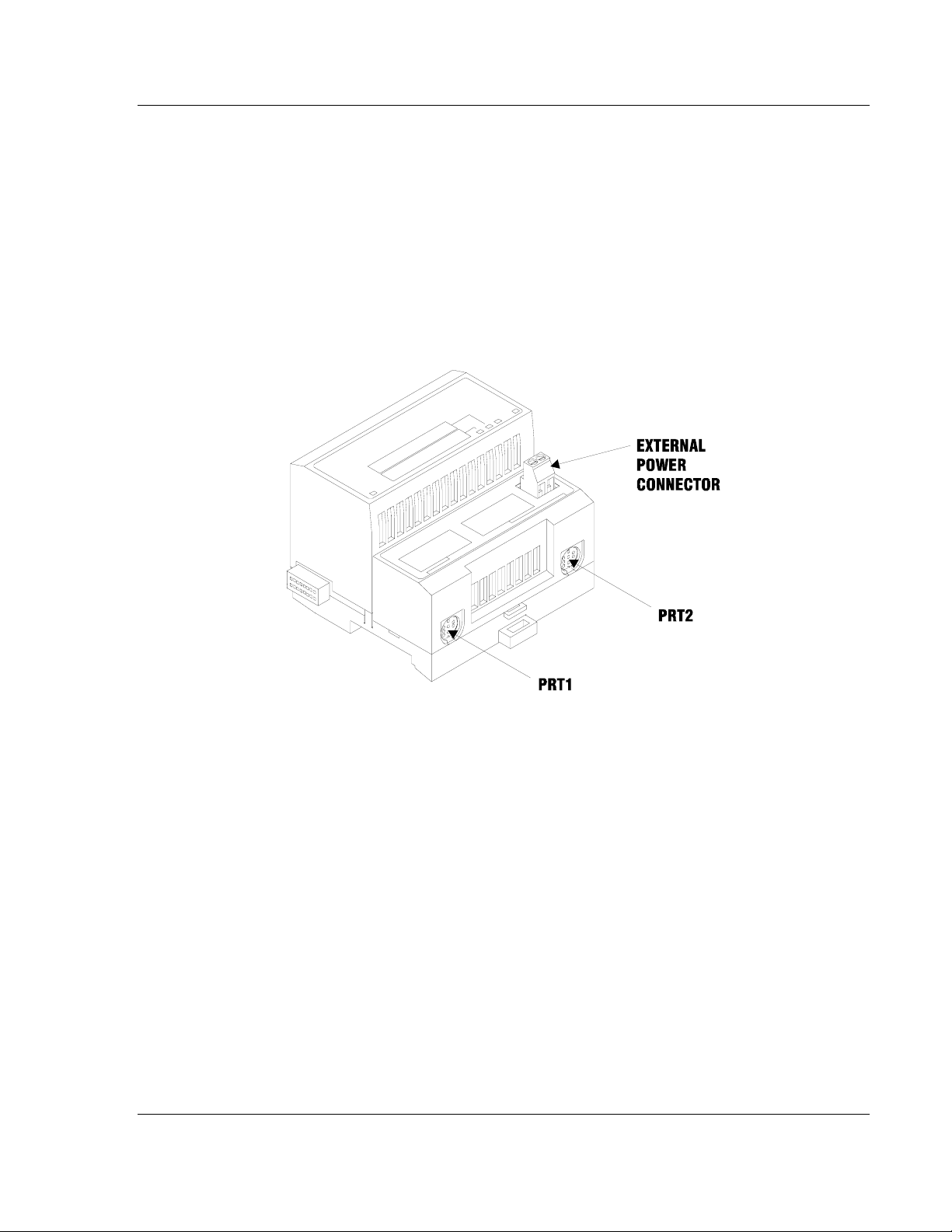
1.5 Installing the Serial Adapter Cables
Two identical serial adapter cables are supplied. Each cable has a locking-type 8
pin Mini-DIN plug on one end and a DB-9 male connector on the other end. The
Mini-DIN connector on each cable is inserted into the Mini-DIN receptacles
marked PRT1 and PRT2 on the Base.
To install the locking-type Mini-DIN connector, slide the spring-loaded sleeve
back while inserting the plug into the receptacle on the Base, and then release
the sleeve when fully seated. The locking mechanism prevents the cable from
being removed during normal operation. To remove the cable, slide the sleeve
back and remove the plug.
1.6 Wiring the Power Connections
External power is supplied to the Base on the 2 pin screw terminal block. The
power supply can be either 24Vdc or 12Vdc, and should be located in close
proximity of the base.
Connect dc common to the COM terminal
Connect +24V dc or +12V dc to the 24VDC terminal

MVI94-GSC-E ♦FLEX Platform Hardware Installation
Generic ASCII Comunication Module User Manual
Page 12 of 60 ProSoft Technology, Inc.
July 6, 2009
Configuration MVI94-GSC-E ♦FLEX Platform
User Manual Generic ASCII Comunication Module
ProSoft Technology, Inc. Page 13 of 60
July 6, 2009
2 Configuration
In This Chapter
Configuration File..................................................................................13
MVI94-GSC-E Configuration File ..........................................................15
Uploading and Downloading the Configuration File...............................17
2.1 Configuration File
The MVI94-GSC-E module stores its configuration in a text file called
configuration, located in the module's flash memory. When the module starts up,
it reads the configuration file and uses the information to control how the GSC-E
protocol interacts with the module's application port(s).
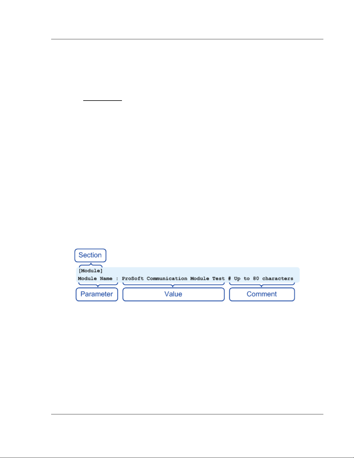
The configuration file is arranged in Sections, with a heading in [ ] characters at
the beginning of each section. Each Section contains a list of Parameters and
Values, followed by an optional Comment that explains the parameter.
The following illustration shows an example of a Section, a Parameter, a Value,
and a Comment.
The Parameter must be followed by a [:] (colon) character. The text following the
[:] is a Value.
The module ignores "comment" text following the [#] character. Use comments to
document your configuration settings.
You can get a sample configuration file for the module in the following places:
Copy (page
17) the configuration from the module's flash memory to your PC
Copy the configuration from the ProSoft Solutions CD-ROM supplied with the
module
Download the configuration from the ProSoft Technology web site at
www.prosoft-technology.com

MVI94-GSC-E ♦FLEX Platform Configuration
Generic ASCII Comunication Module User Manual
Page 14 of 60 ProSoft Technology, Inc.
July 6, 2009
2.1.1 Editing the Configuration File
The configuration file is a plain ASCII text file. Use a text editor such as
Notepad.exe (included with Microsoft Windows) to open and edit the file.
To open the configuration file in Notepad
1 Click the Start button, and then choose Programs
2 Expand the Programs menu, and then choose Accessories.
3 On the Accessories menu, choose Notepad.
4 In Notepad, open the File menu, and then choose Open
5 In the Open dialog box, select "All Files" in the Files of Type: dropdown list.
Tip: Sample configuration files are stored under the LadderLogic folder on the ProSoft Solutions
CD-ROM.
6 Navigate to the folder containing the configuration file, and then select the file
to edit.
7 Click Open to open the file.
8 When you have finished editing, save the file and close Notepad.

Configuration MVI94-GSC-E ♦FLEX Platform
User Manual Generic ASCII Comunication Module
ProSoft Technology, Inc. Page 15 of 60
July 6, 2009
Important: Changes to the configuration file will not take effect until you download the file to the
module, and then reboot the module.
2.2 MVI94-GSC-E Configuration File
The parameters that can be defined for the module are shown in the following
table.
[Section]/Item Value Range Description
[MODULE] Module section header
Module Name: 0 to 80
characters This parameter assigns a name to the module
that can be viewed using the configuration/debug
port. Use this parameter to identify the module
and the configuration file.
Backplane Fail Count: 0 to 65535 This parameter specifies the number of
successive transfer errors that must occur before
the communication ports are shut down. If the
parameter is set to zero, the communication
ports will continue to operate under all
conditions. If the value is set larger than 0 (1 to
65535), communications will cease if the
specified number of failures occur.
[Section]/Item Value Range Description
[GSC Port 0] GSC port definition header
Enabled: Yes or No This parameter defines if this port will be utilized.
If the parameter is set to No, the port is disabled.
A value of Yes will enable the port.
Type: 0 to 15 This parameter specifies the receive termination
characteristics for the port. This value is bit
mapped as follows: Bit 0 = Termination
character(s) used, Bit1=Message timeout used,
Bit2=Intercharacter delay timeout used and
Bit3=Packet size limit used. If the parameter is
set to zero, the port is placed in stream mode.
Baud Rate: From
selected list
of codes
This is the baud rate to be used on the port.
Enter the baud rate as a value. For example, to
select 19K baud, enter 19200. Valid entries for
this field include: 110, 150, 300, 600, 1200,
2400, 4800, 9600, 19200, 28800, 38400, 576
and 115.
Parity: None, Even,
Odd, Mark or
Space
This is the Parity code to be used for the port.
The values are as follows: None, Odd, Even,
Mark and Space.
Data Bits: 5 to 8 This parameter sets the number of data bits for
each word used by the protocol. Valid entries for
this field are 5, 6, 7 and 8.
Stop Bits: 1 or 2 This parameter sets the number of stop bits to be
used with each data value sent. Valid entries for
this field are 1 and 2.

MVI94-GSC-E ♦FLEX Platform Configuration
Generic ASCII Comunication Module User Manual
Page 16 of 60 ProSoft Technology, Inc.
July 6, 2009
[Section]/Item Value Range Description
RTS On: 0 to 65535 This parameter sets the number of milliseconds
to delay after RTS is asserted before the data
will be transmitted. Valid values are in the range
of 0 to 65535.
RTS Off: 0 to 65535 This parameter sets the number of milliseconds
to delay after the last byte of data is sent before
the RTS modem signal will be set low. Valid
values are in the range of 0 to 65535.
Handshaking: NONE,
RTS/CTS,
DTR/DSR or
XON/XOFF
This parameter specifies the handshaking used
on the port. The values are as follows: None=No
hardware or software handshaking, RTS/CTS
hardware handshaking, DTR/DSR hardware
handshaking and XON/XOFF software
handshaking.
Rx Term Char Count: 0 to 12 This parameter is used if bit 0 of the Type
parameter is set. This value (0 to 12) defines the
number of termination characters used to define
the end of received message.
Rx Term Characters: List of up to
12 integer
values
This array of 12 integer values representing the
characters used to define the termination
characters at the end of each received message.
The number of characters to be used in the array
is set in the RTermCnt parameter.
Rx Packet Length: 0 to 4096 This parameter is used if bit 3 is set in the Type
parameter. The parameter sets the length of data
required to be received on the port before
transferring the data to the processor.
Rx Message Timeout: 0 to 65535 This parameter is used if bit 1 is set in the Type
parameter. The parameter sets the number of
milliseconds to wait after the first character is
received on the port before automatically
sending the data to the processor.
Rx Intercharacter
Delay: 0 to 65535 This parameter is used if bit 2 is set in the Type
parameter. The parameter sets the number of
milliseconds to wait between each character
received on the port before sending the data to
the processor.
Rx Swap Bytes: Yes or No This parameter specifies if the data received
should have its bytes swapped before sending
over the backplane.
Tx Message Timeout: 0 to 65535 This parameter specifies the timeout period to
transmit a message out the port. A message
must be transmitted out the port within the
specified timeout period. Message transmission
will be aborted if the timeout is exceeded.
Tx Minimum Delay: 0 to 65535 This parameter specifies the minimum number of
milliseconds to delay before transmitting a
message out the port. This pre-send delay is
applied before the RTS on time. This may be
required when communicating with slow devices.
Tx Swap Bytes: Yes or No This parameter specifies if the data to be
transmitted out the port will have the bytes
swapped from the data presented across the
backplane.

Configuration MVI94-GSC-E ♦FLEX Platform
User Manual Generic ASCII Comunication Module
ProSoft Technology, Inc. Page 17 of 60
July 6, 2009
2.3 Uploading and Downloading the Configuration File
ProSoft modules are shipped with a pre-loaded configuration file. In order to edit
this file, you must transfer the file from the module to your PC. After editing, you
must transfer the file back to the module.
This section describes these procedures.
Important: The illustrations of configuration/debug menus in this section are intended as a general
guide, and may not exactly match the configuration/debug menus in your own module. For specific
information about the configuration/debug menus in your module, refer to The Configuration/Debug
Menu (page 24).
2.3.1 Required Hardware
You can connect directly from your computer’s serial port to the serial port on the
module to view configuration information, perform maintenance, and send
(upload) or receive (download) configuration files.
ProSoft Technology recommends the following minimum hardware to connect
your computer to the module:
80486 based processor (Pentium preferred)
1 megabyte of memory
At least one UART hardware-based serial communications port available.
USB-based virtual UART systems (USB to serial port adapters) often do not
function reliably, especially during binary file transfers, such as when
uploading/downloading configuration files or module firmware upgrades.
A null modem serial cable.
2.3.2 Required Software
In order to send and receive data over the serial port (COM port) on your
computer to the module, you must use a communication program (terminal
emulator).
A simple communication program called HyperTerminal is pre-installed with
recent versions of Microsoft Windows operating systems. If you are connecting
from a machine running DOS, you must obtain and install a compatible
communication program. The following table lists communication programs that
have been tested by ProSoft Technology.
DOS ProComm, as well as several other terminal emulation programs
Windows 3.1 Terminal
Windows 95/98 HyperTerminal
Windows NT/2000/XP HyperTerminal
The module uses the Ymodem file transfer protocol to send (upload) and receive
(download) configuration files from your module. If you use a communication
program that is not on the list above, please be sure that it supports Ymodem file
transfers.

MVI94-GSC-E ♦FLEX Platform Configuration
Generic ASCII Comunication Module User Manual
Page 18 of 60 ProSoft Technology, Inc.
July 6, 2009
2.3.3 Transferring the Configuration File to Your PC
1 Connect your PC to the Configuration/Debug port of the module using a
terminal program such as HyperTerminal. Press [?] to display the main
menu.
2 Press [S] (Send Module Configuration). The message "Press Y key to
confirm configuration send!" is displayed at the bottom of the screen.
3 Press [Y]. The screen now indicates that the module is ready to send.
Configuration MVI94-GSC-E ♦FLEX Platform
User Manual Generic ASCII Comunication Module
ProSoft Technology, Inc. Page 19 of 60
July 6, 2009
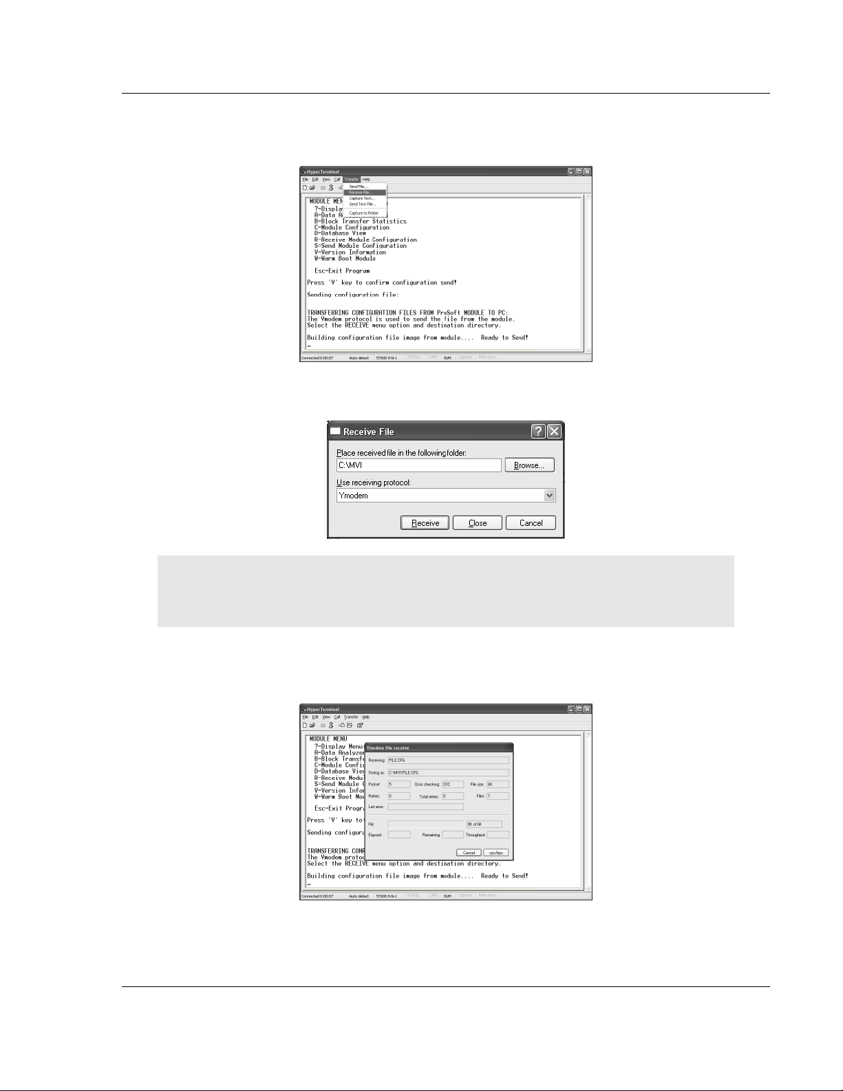
4 From the Transfer menu in HyperTerminal, select Receive File. This action
opens the Receive File dialog box.
5 Use the Browse button to choose a folder on your computer to save the file.
Note: ProSoft Technology suggests that you upload the configuration file pre-loaded on your
module. However, configuration files are also available on the ProSoft CD as well as the
ProSoft Technology web site at www.prosoft-technology.com.
6 Select Ymodem as the receiving protocol.
7 Click the Receive button. This action opens the Ymodem File Receive dialog
box, showing the progress of your file transfer.

MVI94-GSC-E ♦FLEX Platform Configuration
Generic ASCII Comunication Module User Manual
Page 20 of 60 ProSoft Technology, Inc.
July 6, 2009
When the configuration file has been transferred to your PC, the dialog box
will indicate that the transfer is complete.
The configuration file is now on your PC at the location you specified.
8 You can now open and edit the file in a text editor such as Notepad. When
you have finished editing the file, save it and close Notepad.
2.3.4 Transferring the Configuration File to the Module
Perform the following steps to transfer a configuration file from your PC to the
module.
1 Connect your PC to the Configuration/Debug port of the module using a
terminal program such as HyperTerminal. Press [?] to display the main
menu.
Table of contents
Other ProSoft Network Hardware manuals


Popular Network Hardware manuals by other brands


Hameg
Hameg HM6050-2K manual

Patton electronics
Patton electronics 2120 user manual

Polycom
Polycom Real-Time Media Conferencing Platform RMX... Installation & configuration guide

Panasonic
Panasonic Transistors 2SC4691J Specifications

Synology
Synology DX517 manual

Lutron Electronics
Lutron Electronics Smart Bridge quick start guide