PROTEA SODCUTTER 460 User manual

PROTEA TURF EQUIPMENT
Manufacturers of Industrial Lawnmowers, Scarifiers & Sodcutters
Reg. No. CK 1989/023716/23
Vat Reg. No. 4830119907
P.O. Box 1673
Bedfordview
2008
www.proteamachines.com
32 Shaft Rd
Knights, Germiston
Tel: +2711 828 9935
PROTEA SOD CUTTER
MODEL 460
OPERATING INSTRUCTIONS AND SPARE PARTS
MANUAL

Tel: +2711 828 9935
Mobile: +2782 458 7257
P.O. Box 1673 32 Shaft Road
Bedfordview Knights
2008 Germiston
Gauteng Gauteng
South Africa South Africa
Email: [email protected]
Email: sean@proturf.co.za
For further information on any Protea products, please visit our website www.proteamachines.com
Postal Address
Physical Address
Contact Numbers
Email: [email protected]
CONTACT DETAILS:

1. Know your controls. Read the owner's manual 13. Stop the engine whenever you leave the
carefully. Learn how to stop engine quickly in the mower unattended, even for a moment.
event of an emergency.
14. Stop the engine before pushing the mower
2. Ensure the lawn is clear of sticks, stones, across gravel drives, walks or roads.
wire and debris. They could be thrown
by the blade. 15. Do not allow children or people
unfamiliar with these instructions operate
3. Stop the engine and disconnect the spark plug wire the mower.
before checking or working on the mower.
16. On slopes or wet grass, be extra careful of
4. Before use, always visually inspect to see that the your footing.
blade bolts and cutter assembly are not worn or
damaged. Replace worn or damaged blades and 17. Never cut grass by pulling the mower towards
bolts in sets to preserve balance. you.
Damaged blades and worn bolts are a
major hazard. 18. Never use an electrically powered mower in
the rain or when the grass is wet.
5. Check all nuts, bolts and screws often. Always
ensure the mower is in a safe operating condition. 19. Be extremely careful when using a ride on
Use only replacement parts made and guaranteed
mower on slopes.
by the original manufacturer of your mower.
20. Never leave wind-up starters in a wound
6. Add fuel BEFORE starting engine. Avoid spilling condition.
gasoline and do not fill the tank while the engine is
running or while you are smoking. 21. Do not over speed the engine or alter governor
settings. Excessive speed is dangerous
7. Do not mow whilst people, especially children and shortens mower life.
or pets, are in the mowing area.
22. It is advisable to wear suitable eye protection
8. Never use the mower unless the grass catcher , when operating a mower.
or guards provided by the manufacturer,
are in position. 23. Turn the fuel off at the conclusion of mowing
and reduce the throttle setting during
9. Do not mow barefoot or in open sandals. engine run-out.
Wear long trousers and heavy shoes.
24. Store fuel in a cool place in a container
10. Disengage all blade and drive clutches before specifically designed for the purpose.
starting.
25. Never pick up or carry a mower when it is
11. Start the engine carefully with feet well away operating.
from the blades.
12. Do not operate the engine in a confined space where
exhaust fumes (carbon monoxide) can collect.
LAWNMOWER SAFETY PRECAUTIONS
1

SODCUTTER
MODEL 460
TO OPERATE TURF CUTTER AND ATTACHMENTS
Start motor by using choke and throttle lever. Lift Sodcutter by the handle and adjust depth of cut. Have
motor running about 2000 revolutions per minute. Engage cutter bar so that is oscillates, then engage drive
wheels, and lower Sodcutter slowly on to the grass. The cutter blade will automatically dig into the earth as
you move. At the end of the run, disengage both cutter and drive and then lift blade clear off ground by
lifting machine. The Sodcutter blade is adjustable for hard, soft and normal (center position) soil
conditions.
MAINTENANCE INSTRUCTIONS FOR SOD CUTTER
-Keep drive belts adjusted firmly, using adjustable tensioning screws
-Grease countershaft every three (3) months
-Grease wheel bearing every six (6) months
-Grease conrod bushes (120223) and bearings (1124440) daily
-Check machine regularly for loose bolts
-To sharpen turf cutter blade, re-grind top and sides
-Operating conditions should be taken into account when determining maintenance intervals
-Important: Maintain strong camshaft V belt (3602060 / 3602061) tensioning at all times. As soon
as the tension slackens off, drop the camshaft (120200) downwards into the next slotted hole –both
sides. Finer adjustments can be made with the adjuster screw (120153) on the tensioner assembly.
SPECIFICATIONS
ENGINES ADJUSTMENTS
•Honda GX240HX (8HP) Petrol Blade depth of cut: by pin-in-hole
Driven with 6:1 reduction gear box adjuster
•Kohler CH395 (9HP) Petrol “V”Belts: jacking bolts/sliding bearings
Driven with 6:1 reduction gear box Width of cut: 460mm (18 inch)
Cutting Depth: 6-100mm (1/4 –4 inch)
TRANSMISSION CUTTING TIME
A) Three (3) “V”Belts to crank arm Approximately 1500-2000 square
B) Three (3) V Belts to drive rollers meters per day, depending on soil
C) One (1) “V”Belt from motor to counter shaft condition
BEARINGS CUTTING BLADE
Selected ball and pillar block bearings Heavy-duty precision machined, the
material is high tensile, hardened
tempered
PLEASE NOTE: SPECIFICATIONS ARE SUBJECT TO CHANGE WITHOUT PRIOR NOTICE

SPARE PARTS
PAGE 1
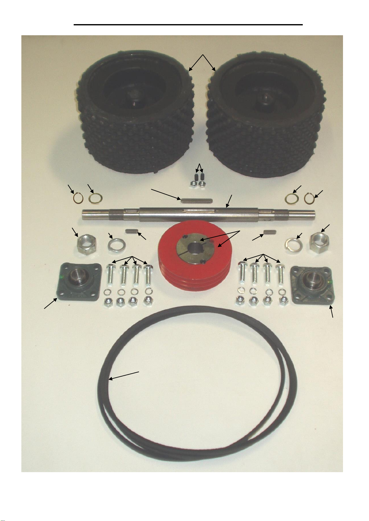
FIGURE 1: FRONT WHEEL ASSEMBLY
1
2
3
4
4
5
5
6
6
8
7
9
9
10
11
11
12
13
12
13

ILLUS. NO DESCRIPTION PART NO
1 FRONT WHEEL (EACH) 120340
2 M10x20 GRUB SCREW + M10 NUT STANDARD
3 FRONT WHEEL PULLEY (COMES WITH TAPER LOCK) 120155
4 FRONT WHEEL BEARING 120446
5 M12x40 SET SCREW + M12 SPRING WASHER + M12 NYLOC NUT STANDARD
6 M30 FRONT WHEEL SPRING WASHER STANDARD
7 "V" BELT - FRONT WHEEL (3 PER MACHINE) 3602050
8 FRONT WHEEL SHAFT 120341
9 FRONT WHEEL KEY (2 PER MACHINE) 120514
10 FRONT WHEEL PULLEY KEY 120515
11 1 1/8" FRONT WHEEL LOCKNUT STANDARD
12 SHAFT WASHER 120585
13 25mm EXTERNAL CIRCLIP 1501052
PAGE 2
REFER FIG. 1

PAGE 3
FIGURE 2: MAIN FRAME ASSEMBLY
1
2
3
6
7
8
9
10
11
12
13
14
15
16
17
18
19

ILLUS. NO DESCRIPTION PART NO
1 HONDA GX240HX - 6:1 REDUCTION 6200500H
1 KOHLER CH395 - 6:1 REDUCTION 6200500K
2 ENGINE PULLEY: HONDA 120151
2 ENGINE PULLEY: KOHLER 120150
3 THROTTLE CABLE 656720
4 M8x25 ENGINE PULLEY GRUB SCREW (NOT SHOWN) STANDARD
5 ENGINE PULLEY KEY (NOT SHOWN) 120516
6 ENGINE PULLEY CAP & BOLT 120154
7 ENGINE GUARD: HONDA 120191
7 ENGINE GUARD: KOHLER 120192
8 MAIN FRAME 120230
9 "V" BELT GUIDE 120519
10 BELT GUARD BRACKET 120555
11 BELT TENSIONER LEVER 120152
12 HANDLE GRIPS (SET) 1851069
13 BELT TENSIONER LEVER BRACKET 120509
14 M10x70 SET SCREW + M10 NUT STANDARD
15 M8x40 SET SCREW + M8 NUT STANDARD
16 EXHAUST DEFLECTOR 658362
17 SWIVEL CASTOR WHEEL 6361800
18 BELT GUARD RUBBER 120497
19 BELT GUARD 120495
PAGE 4
REFER FIG. 2

PAGE 5
FIGURE 3: COUNTERSHAFT ASSEMBLY
2
1
3
4
5
5
6
6
8
8
9
9
7
7
7
7
10
10
11
12
13
13

ILLUS. NO DESCRIPTION PART NO
1 COUNTERSHAFT 120331
2 COUNTERSHAFT PULLEY: 3 GROOVES (COMES WITH GRUB SCREWS) 120330
3 COUNTERSHAFT PULLEY: 1 GROOVE (COMES WITH TAPERLOCK) 120332
4 "V" BELT - COUNTERSHAFT (1 PER MACHINE) 3602040
5 COUNTERSHAFT BEARINGS 1125550
6 M12 SPRING WASHER STANDARD
7 M12x40 SET SCREW STANDARD
8 M12 NUT STANDARD
9 M12 FLAT WASHER STANDARD
10 25mm EXTERNAL CIRCLIP 1501052
11 COUNTERSHAFT KEY (LONG) 120512
12 COUNTERSHAFT KEY (SHORT) 120513
13 SHAFT WASHER 120585
PAGE 6
REFER FIG. 3

PAGE 7
FIGURE 4: HEIGHT ADJUSTER LEVER ASSEMBLY
1
2
3
4
4
4
4
5
5
5
5
6
6
7
8
9
10
11
12
12
13
13
14
15
15
16
16
17
17
17
17
18
18
19
20

ILLUS. NO DESCRIPTION PART NO
1 HEIGHT ADJUSTER LEVER 120020
2 BELT TENSIONER LEVER 120152
3 HEIGHT ADJUSTER ARM 120201
4 HEIGHT ADJUSTER LEVER PIVOT BOLT 120212
5 PIVOT SLEEVE 120211
6 M10 CASTLE NUT 2641303
7 HEIGHT ADJUSTER CLIP 120203
8 HEIGHT ADJUSTMENT PIN 120202
9 HEIGHT ADJUSTER RUBBERS (SET) 120510
10 HEIGHT ADJUSTER SUPPORT ANGLE 120511
11 SIDE ARM 120210
12 SIDE ARM BUSH 120213
13 M10x40 CAP SCREW + FLAT WASHER + SPRING WASHER + NYLOC NUT STANDARD
14 SOD CUTTER BLADE 120174
15 5/8" UNF CASTLE NUT 2641300
16 SIDE ARM GREASE COVER 120590
17 M3x50 SPLIT PIN STANDARD
18 M16 SPRING WASHER STANDARD
19 M10x70 SET SCREW + M10 FLAT WASHER + 2xM10 NUTS STANDARD
20 HEIGHT ADJUSTER REINFORCING PLATE 120700
PAGE 8
REFER FIG. 4
PAGE 9
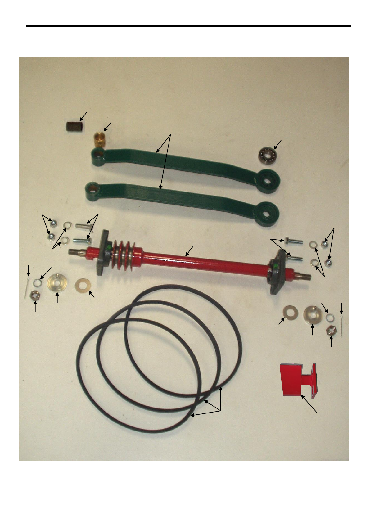
FIGURE 5: CONROD AND CAMSHAFT ASSEMBLY
1
2
3
2
4
6
5
7
7
8
8
9
9
10
10
11
11
12
13
13
14
14
15
15

ILLUS. NO DESCRIPTION PART NO
1 CONROD ASSY (C/W BEARING (1124440) & BRONZE BUSH (120223)) 120220
2 CAMSHAFT ASSY 120200
3 CAMSHAFT "V" BELTS - STANDARD (3 PER MACHINE) 3602060
3 CAMSHAFT TRUEBLUE "V" BELTS - HEAVY DUTY (3 PER MACHINE) 3602061
4 CONROD SWIVEL BEARING 1124440
5 SIDE ARM INNER BUSH FOR BRONZE BUSH 120213
6 CONROD BRONZE BUSH 120223
7 OUTER GREASE COVER 120570
8 INNER GREASE COVER 120225
9 5/8" UNF CASTLE NUT 2641300
10 M12x40 SET SCREW STANDARD
11 M12 NYLOC NUT STANDARD
12 CAMSHAFT "V" BELT GUIDE 120519
13 M12 FLAT WASHER STANDARD
14 M16 SPRING WASHER STANDARD
15 M3x50 SPLIT PIN STANDARD
PAGE 10
REFER FIG. 5
PAGE 11
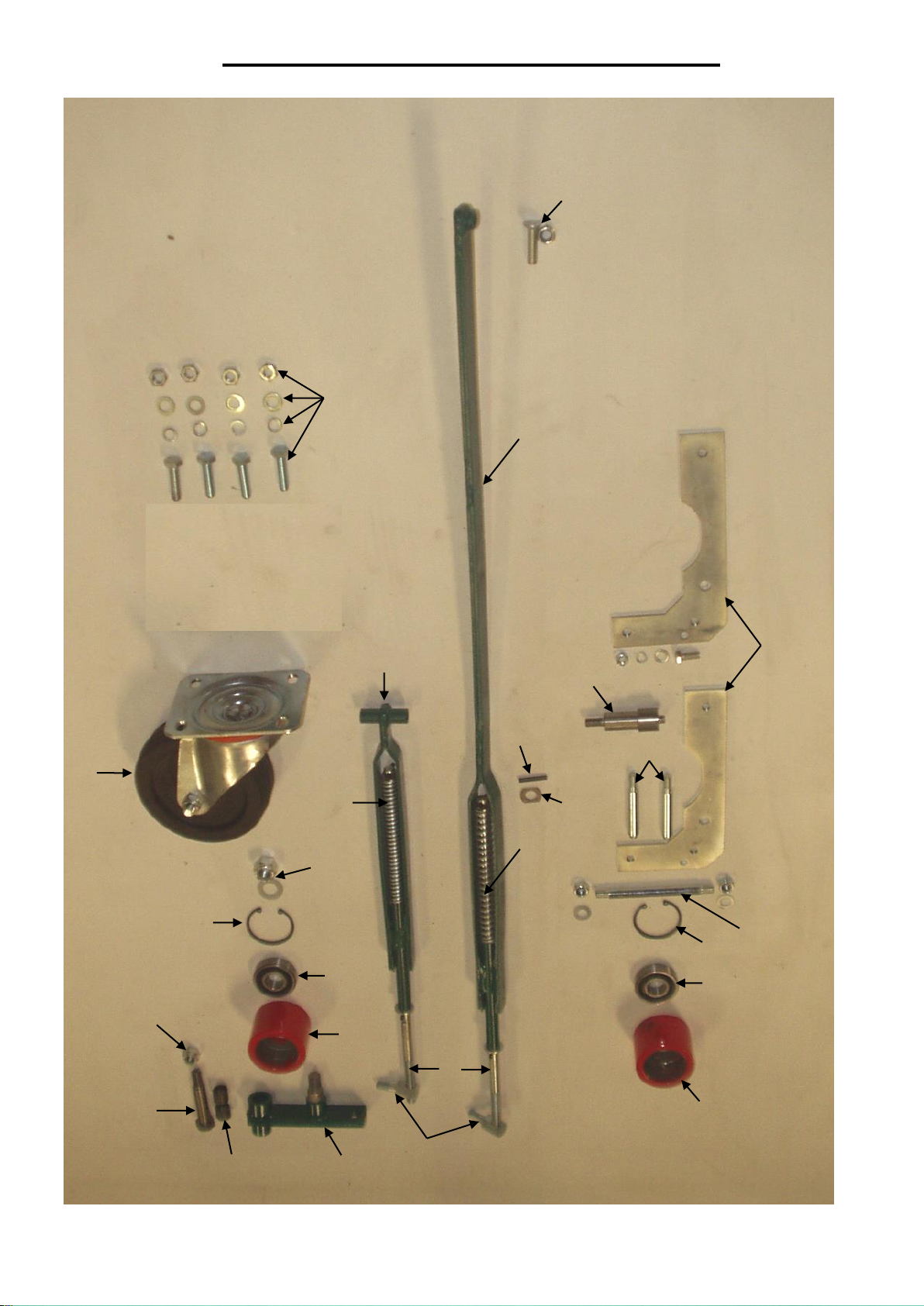
FIGURE 6: BELT TENSIONERS
2
3
1
4
5
6
7
8
9
10
10
11
12
13
14
15
16
17
8
9
18
19
20
21
22
23

ILLUS. NO DESCRIPTION PART NO
1 ENGINE PULLEY TENSIONER COMPLETE ASSEMBLY (LONG) 120181
2 ENGINE PULLEY TENSIONER SPRING 120560
3 SPRING ROD 120179
4 1/8" x 1" SELLOCK PIN STANDARD
5 FRONT WHEEL PULLEY TENSIONER COMPLETE ASSEMBLY (SHORT) 120180
6 TENSIONER WASHER 120575
7 FRONT WHEEL PULLEY TENSIONER SPRING 120562
8 6304 JOCKEY PULLEY BEARING 1123423
9 52mm INTERNAL CIRCLIP 1502520
10 JOCKEY PULLEY 120182
11 M10x40 COUNTERSUNK SCREW + M10 NYLOC NUT STANDARD
12 FRONT WHEEL BELT TENSIONER SIDE PLATES (EACH) 120185.1
13 FRONT WHEEL BELT TENSIONER BEARING SHAFT 120185.4
14 FRONT WHEEL BELT TENSIONER PIVOT BAR 120550
15 FRONT WHEEL BELT TENSIONER STUD 120185.2
16 SWIVEL CASTOR WHEEL 6361800
17 M10x30 SET SCREW + FLAT WASHER + SPRING WASHER + NUT STANDARD
18 JOCKEY PULLEY BRACKET 120021
19 ADJUSTER SCREW 120149
20 JOCKEY PULLEY BRACKET BUSH 3111030
21 1/2" UNF NYLOC NUT STANDARD
22 JOCKEY PULLEY PIVOT BOLT 120190
23 5/8" UNF NYLOC NUT + M16 FLAT WASHER STANDARD
PAGE 12
REFER FIG. 6
Other manuals for SODCUTTER 460
1
Table of contents
Other PROTEA Cutter manuals

Popular Cutter manuals by other brands

Maruyama
Maruyama MC2600RS Owner's/operator's manual

ROKAMAT
ROKAMAT PIRANHA Translation of the original instructions

Ilsco
Ilsco TaskMaster TB-CUT25-I instruction manual

QEP
QEP Vitrex Clinker XL owner's manual

Profitech Diamant
Profitech Diamant SC 350-6 instruction manual

Parkside
Parkside PSFS 250 A1 manual


