PROTEA SODCUTTER 460 Guide

PROTEA SODCUTTER MODEL 460
OPERATING INSTRUCTIONS & SPARES MANUAL

Ref. No.: CK 91/04496/23 Vat No.: 4830119907
Tel: 011 828 9935
011 822 1850
Fax: 011 828 6869
Mobile: 082 458 7257
Physical Address
BEDFORDVIEW
Telephone/Fax Numbers
Email: [email protected]
Email: sean@proturf.co.za
For further information on any Protea products, please visit our website www.proturf.co.za
Postal Address
Germiston
Gauteng
South Africa
Knights
2008 GAUTENG
Manufacturers of Protea Range of Mowers, Sodcutters, Scarifiers
PROTEA TURF EQUIPMENT cc
SOUTH AFRICA
32 Shaft Road
CONTACT DETAILS:
P.O.BOX 1673

1Know your controls. Read the owner's manual 13 Stop the engine whenever you leave the
carefully. Learn how to stop engine quickly in an mower, even for a moment.
emergency. 14 Stop the engine before pushing mower
2Make sure the lawn is clear of sticks, stones, across gravel drives, walks or roads.
bones, wire and debris. They could be thrown
by the blade. 15 Do not allow children or people
unfamiliar with these instructions to use
3Stop the engine and disconnect spark plug wire the mower.
before checking or working on the mower. 16 On slopes or wet grass, be extra careful of
4Before using, always visually inspect to see that your footing.
blade bolts and cutter assembly are not worn or
damaged. Replace worn or damaged blades 17 Never cut grass by pulling the mower towards
bolts in sets to preserve balance. you.
Damaged blades and worn bolts are a
major hazard. 18 Never use an electrically powered mower in
the rain or when grass is wet.
5Check all nuts, bolts and screws often, always
be sure the mower is in safe operating 19 Be extremely careful when using a ride on
condition. Use only replacement parts made
mower on slopes.
and guaranteed by the original manufacturer
of your mower 20 Never leave wind-up starters in a wound
condition.
6
Add fuel BEFORE starting engine. Avoid spilling
petrol and do not fill the tank while the engine is 21 Do not over speed the engine or alter governor
running or while you are smoking. settings. Excessive speed is dangerous
and shortens mower life.
7Do not mow whilst people, especially children
or pets are in the mowing area. 22 It is advisable to wear suitable eye protection
when operating a mower.
8Never use the mower unless the grass catcher ,
or guards provided by the manufacturer, 23 Turn the fuel off at the conclusion of mowing
are in position. and reduce the throttle setting during
engine run-ou.
9Do not mow barefoot or in open sandals.
Wear long trousers and heavy shoes. 24 Store fuel in a cool place in a container
specifically designed for the purpose. In
10 Disengage all blade and drive clutches before general, plastic containers are unsuitable.
starting.
25 Never pick up or carry a mower when it is
11 Start the engine carefully with feet well away operating.
from the blades.
12 Do not operate engine in a confined space where
exhaust fumes (carbon monoxide) can collect.
POWER LAWNMOWER SAFETY PRECAUTIONS

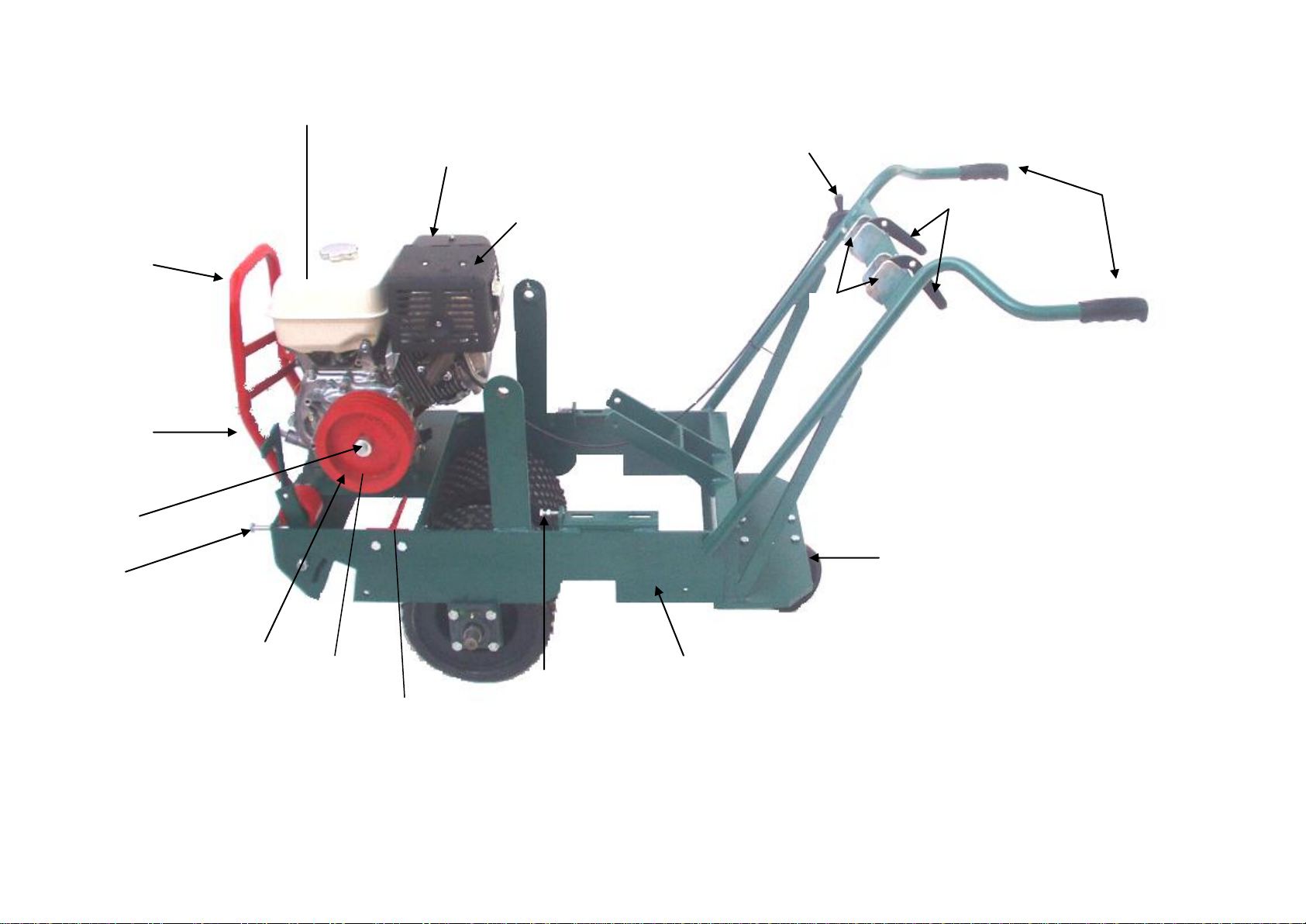
SODCUTTER
MODEL 460
TO OPERATE TURF CUTTER AND ATTACHMENTS
Start motor by using choke and throttle lever. Lift Sodcutter by the handle and adjust depth of cut. Have
motor running about 2000 revolutions per minute. Engage cutter bar so that is oscillates, then engage
drive wheels, and lower Sodcutter slowly on to the grass. The cutter blade will automatically dig into the
earth as you move. At the end of the run, disengage both cutter and drive and then lift blade clear off
ground by lifting machine. The Sodcutter blade is adjustable for hard, soft and normal (center position)
soil condition.
MAINTENANCE INSTRUCTION FOR TURF CUTTER
-Keep drive belts adjusted firmly, using adjustable tensioning screws
-Grease countershaft every three (3) months
-Grease wheel bearing every six (6) months
-Grease conrod bearings 120223 and 112440 daily
-Check machine regularly for loose bolts
-To sharpen turf cutter blade, re-grind top and sides
-Operating conditions should be taken into account when determining maintenance intervals
-Important: Maintain strong camshaft V belt (3602060) tensioning at all times. As soon as the
tensioning slackens off, drop the camshaft (120200) downwards into the next slotted hole –both
sides. Finer adjustments can be made with the adjuster screw (120153) on the tensioner assembly
SPECIFICATIONS
ENGINES ADJUSTMENTS
Honda GX240 HX 5,9kw (8HP) Petrol Blade depth of cut: by pin-in-hole
Driven with 6:1 reduction gear box adjuster
V Belts: jacking bolts/sliding bearings
Width of cut: 460mm (18 inch)
Cutting Depth: 6-100mm (1/4 –4 inch)
TRANSMISSION CUTTING TIME
A) Three (3) V Belts to crank arm Approximately 1500-2000 square
B) Three (3) V Belts to drive rollers meter per day, depending on soil
C) One (1) V Belts from motor to counter shaft conditions
BEARINGS OPTIONAL ACCERORIES
Selected ball and pillar block bearings - Trencher blade
Bronze bearings fitted with grease nipples - Slitter blades (3,4 and 5 blades)
CUTTING BLADE
Heavy-duty precision machined, the
material is high tensile, hardened and tempered
SPECIFICATIONS ARE SUBJECT TO CHANGE WITHOUT PRIOR NOTICE

SPARE PARTS

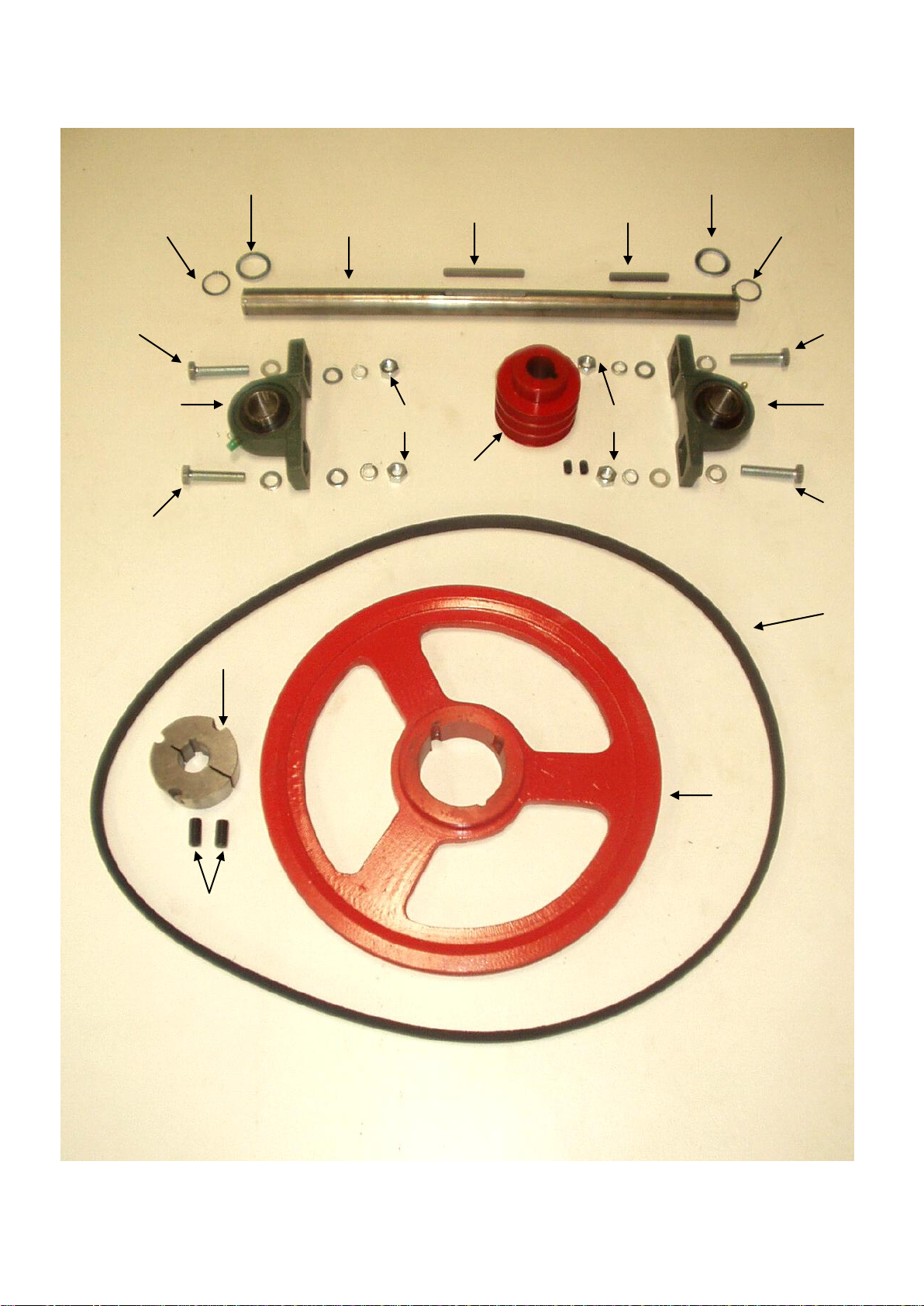
FRONT WHEEL ASSEMBLY
1
2
10
8
9
12
11
9
12
11
3
6
7
4
4
5
5
PAGE 1

FIG
NO
DESCRIPTIONS
1 FRONT WHEEL SOD/ 120340 2 off
2 SQUARE HEAD SCREW BG/ 3162322 2 off
3 FRONT WHEEL PULLEY SOD/ 120155 1 off
4 FRONT WHEEL BEARING SOD/ 120446 2 off
5 HEX BOLT & NUT 8 off
6 FRONT WHEEL PULLEY TAPER LOCK SOD/ 120595 1 off
7 FRONT WHEEL "V" BELT SOD/ 3602050 3 off
8 FRONT WHEEL SHAFT SOD/ 120341 1 off
9 FRONT WHEEL KEY SOD/ 120514 2 off
10 FRONT WHEEL PULLEY KEY SOD/ 120515 1 off
11 FRONT WHEEL SHAFT LOCKNUT SOD/ 120345 2 off
12 FRONT WHEEL SHAFT SPRING WASHERS 2 off
12 FRONT WHEEL SPIKE (for old steel drum) not shown 96/ m-c
FRONT WHEEL ASSY.
M12 x 40
SOD/120141
PART NUMBER
QTY
M30
PAGE 2
9
13
4
14
7
3
12
11
16
15
8
6
1
2
MAIN FRAME ASSEMBLY
17
18
PAGE 3
20

FIG
NO
DESCRIPTIONS
1
HONDA GX240 HX 8HP- 6:1 REDUCTION SOD/ 6200500 1 off
2 ENGINE PULLEY SOD/ 120151 1 off
3 THROTTLE CABLE HD/ 656720 1 off
4 ENGINE PULLEY M8 x 12 GRUB SCREW 1 off
5
ENGINE PULLEY KEY: NOT SHOWN SOD/ 120516 1 off
6 ENGINE PULLEY CAP & BOLT SOD/ 120154 1 off
7 AIR FILTER 17210-ZE2-505 1 off
8
EXHAUST MUFFLER (COMPLETE) 1 off
9 ENGINE GUARD SOD/ 120191 1 off
10
STARTER ASSY: NOT SHOWN 1 off
11 MAIN FRAME SOD/ 120230 1 off
12
"V" BELT GUIDE: CAMSHAFT SOD/ 120519 1 off
13 BELT GUARD BRACKET SOD/ 120555 1 off
14 BELT TENSIONER LEVER SOD/ 120152 2 off
15 HANDLE GRIP SI/ 1851071 2 off
16 BELT TENSIONER LEVER BRACKET SOD/ 120509 2 off
17 M10 x 70 SCREW 1 off
18 M8 x 40 SCREW 2 off
19 EXHAUST DEFLECTOR HD/ 658362 1 off
20 SWIVEL WHEEL SOD/ 6361800 1 off
21 BELT GUARD RUBBER (Not Shown) SOD/ 120497 1 off
22 BELT GUARD (Not Shown) SOD/ 120495 1 off
MAIN FRAME ASSEMBLY
18310-ZE2-W60
28400-ZE2-W01ZA
PART NUMBER
QTY
PAGE 4
COUNTERSHAFT ASSEMBLY
1
8
7
8
5
4
3
9
12
11
2
10
14
13
5
7
7
7
10
9
PAGE 5

DESCRIPTIONS
1 COUNTER SHAFT SOD/ 120331 1 off
2 C/SHAFT PULLEY: 3 GROOVES c/w Grubscrew SOD/ 120330 1 off
3
C/SHAFT PULLEY: 1 GROOVE SOD/ 120332 1 off
4 C/SHAFT/ENGINE "V" BELTS SOD/ 3602040 1 off
5 C/SHAFT BEARINGS SOD/ 1125550 2 off
7 HEX BOLT 4 off
8 HEX NUT M12 4 off
9 FLAT WASHER SOD/ 120600 4 off
10 CIRCLIP EXT. M24 2 off
11 C/SHAFT KEY LONG SOD/ 120512 1 off
12 C/SHAFT KEY SHORT SOD/ 120513 1 off
13 C/SHAFT TAPER LOCK SOD/ 120580 1 off
14 TAPER LOCK GRUBSCREW 2off
15 "V" BELT GUARD (Not Shown) SOD/ 120495 1off
COUNTERSHAFT ASSEMBLY
7/16" BSW x 7/8"
PART NUMBER
QTY
M12 x 40
FIG
NO
PAGE 6
12
7
11
10
9
8
3
6
1
5
2
4
5
4
6
16
17
13
15
18
6
14
17
19
18
12
16
15
13
4
4
5
6
5
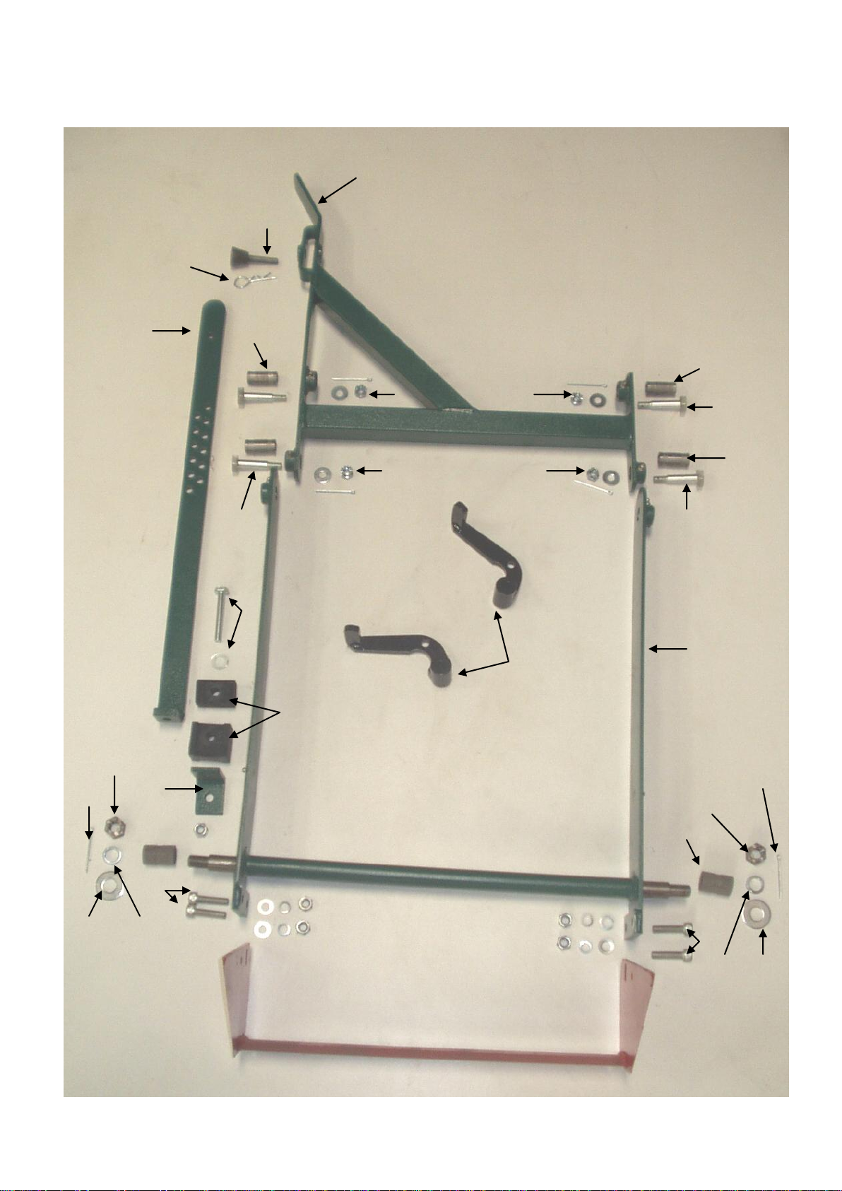
HEIGHT ADJUSTER LEVER ASSEMBLY
PAGE 7

FIG
NO
DESCRIPTIONS
1 HEIGHT ADJUSTER LEVER SOD/ 120020 1 off
2 BELT TENSIONER LEVER New type from 16/3/2015 SOD/ 120152 2 off
3 HEIGHT ADJUSTER ARM SOD/ 120201 1 off
4 CUTTER HANDLE PIVOT BOLT SOD/ 120212 4 off
5 PIVOT SLEEVE SOD/ 120211 4 off
6 CUTTER HANDLE CASTLE NUT M10 4 off
7 SAFETY CLIP SOD/ 120203 1 off
8 HEIGHT ADJUSTER ARM PIN SOD/ 120202 1 off
9
HEIGHT ADJUSTER RUBBER (SET) SOD/ 120510 1 off
10 HEIGHT ADJUSTER ANGLE SUPPORT SOD/ 120511 1 off
11 SIDE ARM SOD/ 120210 1 off
12 SIDE ARM BUSH SOD/ 120213 2 off
13 BLADE/BOLT/NUT 4 off
14 SODCUTTER BLADE SOD/ 120174 1 off
15 SIDE ARM CASTLE NUT 5/8" SOD/ 2641300 2 off
16 SIDE ARM GREASE COVER SOD/ 120590 2 off
17 SPLIT PIN 2 off
18 SPRING WASHER 2 off
19 HIGH TENSILE BOLT 1off
HEIGHT ADJUSTER LEVER ASSY.
M10 CASTLE NUT
M10 x 40
M3 x 50
PART NUMBER
QTY
M16
M10 x 70
PAGE 8

1
10
11
11
6
8
3
2
7
9
4
8
9
7
10
5
CONROD AND CAMSHAFT ASSEMBLY
PAGE 9

FIG
NO
DESCRIPTIONS
1 CONROD ASSY.- C/BEARING SOD/ 120220 2 off
2 CAMSHAFT ASSY. SOD/ 120200 1 off
3 CAMSHAFT "V" BELTS SOD/ 3602060 3 off
4 CONROD BEARING SOD/ 112440 2 off
5
HEX BOLT (FLAT HEAD) 1 off
6 CONROD BRONZE BUSH SOD/ 120223 2 off
7 OUTER GREASE COVER SOD/ 120570 2 off
8 INNER GREASE COVER SOD/ 120225 2 off
9 CAMSHAFT CASTLE NUT SOD/ 2641300 2 off
10
HEX BOLT (STANDARD) 3 off
11 HEX NUT M12 2 off
12
CAMSHAFT "V" BELT GUIDE: Not Shown SOD/ 120519 1 off
13 SIDE ARM INNER BUSH FOR BRONZE BUSH SOD/ 120213 1 off
CONROD & CAMSHAFT ASSY.
M12 x 40
M12 x 40
PART NUMBER
QTY
YOU CAN FIT THE NEW GREASE COVER (7) ON THE OLD CONROD BEARING, BUT THE CIRCLIP MUST BE REMOVED.
PLEASE NOTE
THE OLD TYPE CONROD BEARING (4) WAS SECURED WITH A CIRCLIP. THE NEW CONROD BEARING
IS SECURED WITH A NEW OUTER GREASE COVER (7) AND CASTLE NUT (9) WITHOUT THE CIRCLIP.
PLEASE NOTE
PAGE 10
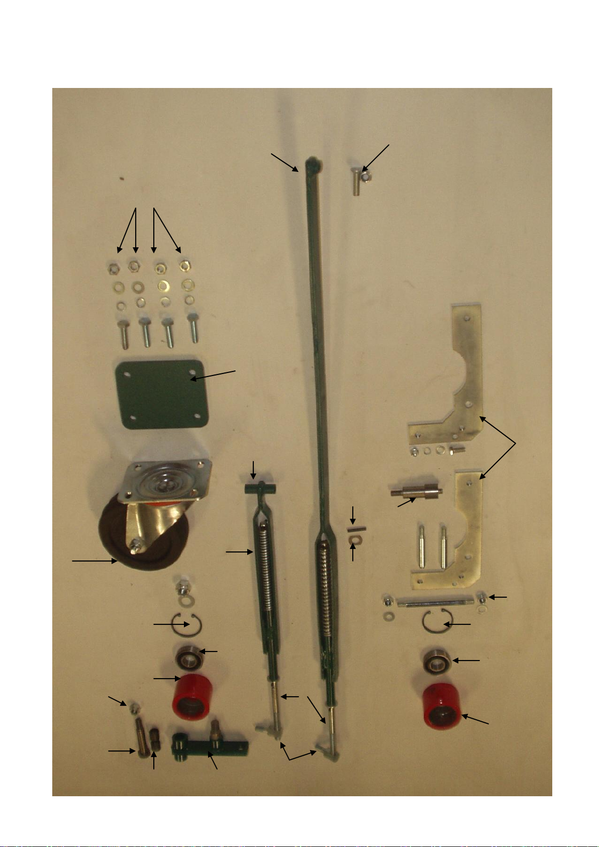
BELT TENSIONERS
17
1
11
23
12
16
5
7
2
9
8
10
21
22
20
18
19
3
4
6
13
15
10
8
9
14
PAGE 11

FIG
NO
DESCRIPTIONS
1 ENGINE PULLEY TENSIONER ASSY SOD/ 120181 1 off
2 ENGINE PULLEY TENSIONER SPRING SOD/ 120560 1 off
3 SPRING ROD SOD/ 120179 2 off
4 M5 x 20 SELLOCK PIN 1 off
5 FRONT WHEEL PULLEY TENSIONER ASSY SOD/ 120180 1 off
6 TENSIONER WASHER SOD/ 120575 1 off
7 FRONT WHEEL PULLEY TENSIONER SPRING SOD/ 120562 1 off
8 JOCKEY PULLEY BEARING 6304 BG/ 1123423 1 off
9 INT. CIRCLIP SOD/ 1502520 1 off
10 FRONT JOCKEY PULLEY SOD/ 120182 1 off
11
M10 x 40 COUNTERSUNK SCREW c/w NUT 1 off
12 FRONT BELT TENISONER SIDE PLATES SOD/ 120185.1 2 off
13 FRONT BELT TENISONER BEARING SHAFT SOD/ 120158.4 1 off
14
FRONT TENSIONER PIVOT BAR c/w NUTS SOD/ 120550 1 off
15 FRONT TENSIONER STUD SOD/ 120158.2 2 off
16 SWIVEL WHEEL SOD/ 6361800 1 off
17
HEX BOLT M10 x 25 c/w NUTS & WASHER 4 off
18
JOCKEY PULLEY BRACKET: FRONT SOD/ 120021 1 off
19 ADJUSTER SCREW SOD/ 120149 2 off
20 JOCKEY PULLEY BUSH BG/ 3111030 2 off
21 NYLOC NUT SOD/ 2641300 1 off
22 JOCKEY PULLEY PIVOT BOLT SOD/ 120190 1 off
23 SWIVEL WHEEL PACKING OBSELETE SOD/ 120558 1 off
BELT TENSIONERS
PART NUMBER
QTY
PAGE 12
Other manuals for SODCUTTER 460
1
Table of contents
Other PROTEA Cutter manuals


