Protech Machinery P240T User manual

P240T Skid-Steer Post-Driver
WOOLRIDGE FARM
HARTPURY
GLOUCESTERSHIRE
GL19 3BG
Page | 2
FIRST : AT DELIVERY TIME
______________________________________________________________________
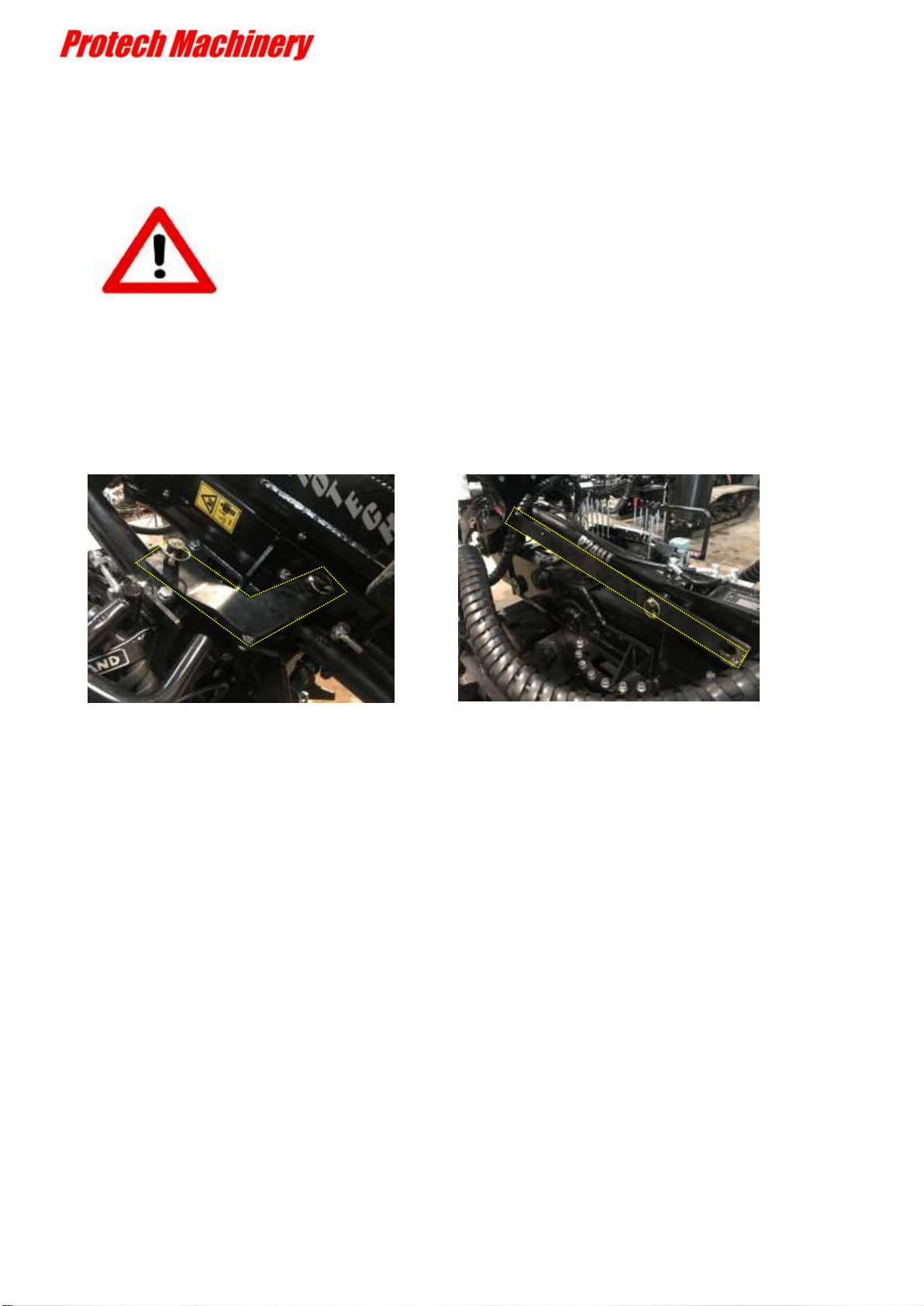
When delivered in a container, the machine will be folded with stay bars and hoses
and rock spike will be standing in the way of the mast.
Before using the mast with hydraulics, all parts must be cleared.
Keep your stay bars for transportation

Page | 3
EC DECLARATION OF CONFORMITY
Conforming to EEC Directive 98/37/EC
We Protech Machinery Ltd
Of Woolridge Farm,
Gloucester Road,
Hartpury,
Gloucestershire.
GL19 3BG
Hereby declare that the product: P240T SKIDSTEER POST-DRIVER
Product Code P240T
Serial Number series
Manufactured by the above Company complies with the required provisions of the
Directive 98/37/EC
To effect the correct application of the safety requirements stated in the EEC Directives,
the following standards and/or technical specification have been used:
BS EN ISO 12100 : 2010 Safety of Machinery - General principles for Design; Risk assessment &
risk reduction
BS EN 953 : 1997 + A1 : 2009 Safety of Machinery - Guards: General requirements for the design
& construction of fixed & moveable guards.
BS EN 349 : 1993 + A1 : 2008 Safety of Machinery - Minimum gaps to avoid crushing of parts of
the human body.
BS EN 13857 : 2008 Safety of Machinery –Safety distances to prevent hazard zones being
reached by upper & lower limbs.
BS EN 4413 : 2010 Hydraulic fluid power - General rules & safety requirements for systems & their
components
BS 5401: 1990 Guide to information content and presentation of operator’s manuals provided for
tractors and machinery for agriculture and forestry.
Signed
On behalf of Protech Machinery
Date…Tuesday, 28 January 2020

Page | 4
LIST OF CONTENTS
______________________________________________________________________
INTRODUCTION.............................................................................................................................5
PRODUCT SPECIFICATION..........................................................................................................5
PARTS REFERENCE.......................................................................................................................6
SAFETY STATEMENT...................................................................................................................8
SAFETY INFORMATION...............................................................................................................9
PERSONAL PROTECTIVE EQUIPMENT...................................................................................12
MACHINE OPERATION...............................................................................................................13
MACHINE SAFETY DECALS......................................................................................................14
CONTROL FUNCTIONS OF THE POST DRIVER.....................................................................15
SLEW ARM....................................................................................................................................16
TELESCOPIC ARM.......................................................................................................................16
REAR LEG......................................................................................................................................16
MAST FORWARD AND SIDE TILT............................................................................................17
POST-DRIVER WEIGHT CONTROL ..........................................................................................17
TELEMAST CONTROL ................................................................................................................17
ROCK SPIKE CONTROL..............................................................................................................18
AUGER DRIVE..............................................................................................................................19
AUTO-LEVEL................................................................................................................................21
Auto-level setup ..............................................................................................................................22
USING THE POST DRIVING EQUIPMENT ...............................................................................23
MAINTENANCE............................................................................................................................24
TRANSPORT..................................................................................................................................25

Page | 5
INTRODUCTION
______________________________________________________________________
IMPORTANT NOTICE
This manual must be read and fully understood before operating this machine.
Whenever any doubt exists please contact Protech Machinery for assistance. If the
machine is resold the Manual must be transmitted to the new owner.
Dear customer,
Thank you for purchasing a Protech Post Driver. Protech machinery Ltd has produced this
User Guide to assist and help you get the most from your post driver.
This manual is line with the relevant Health and Safety regulations to assist you with
operating this machine without harm to yourself.
You should be aware that any person operating this machine with your permission must
be given adequate guidance and information to allow him or her to use the machine safely.
Whereas every effort has been made to ensure the Post Driver conforms to Protech policy
of quality, the machine cannot be expected to withstand abuse caused by misuse and
negligence by the operator.
PRODUCT SPECIFICATION

Page | 6
Each machine will have a degree of customization. Final definition on each sales order.
PARTS REFERENCE
P240T
Machine overall
max
height
4.6 m
Overall Length
1.3 m
Overall machine
Width
2.4 m
Weight
1140 kg
Auger Drive
110 kg
P240T Standard configuration
P240T configuration
✓300kg hammer
✓180 deg hydraulic operated slew
✓Tele arm 500 mm
✓all controls on the machine
✓1500 mm telescopic mast extension
✓75 mm diametre rock spike and hydraulic extractor (can drive 12ft posts)
✓Steel toolbox
✓Flow limiting valve to protect the system
Options for P240T :
o Post twister
o Tractor frame (3 points linkage)
o Auger drive + 4" and 6" Rock Drill
o 2-Axis Auto-level system
Page | 7
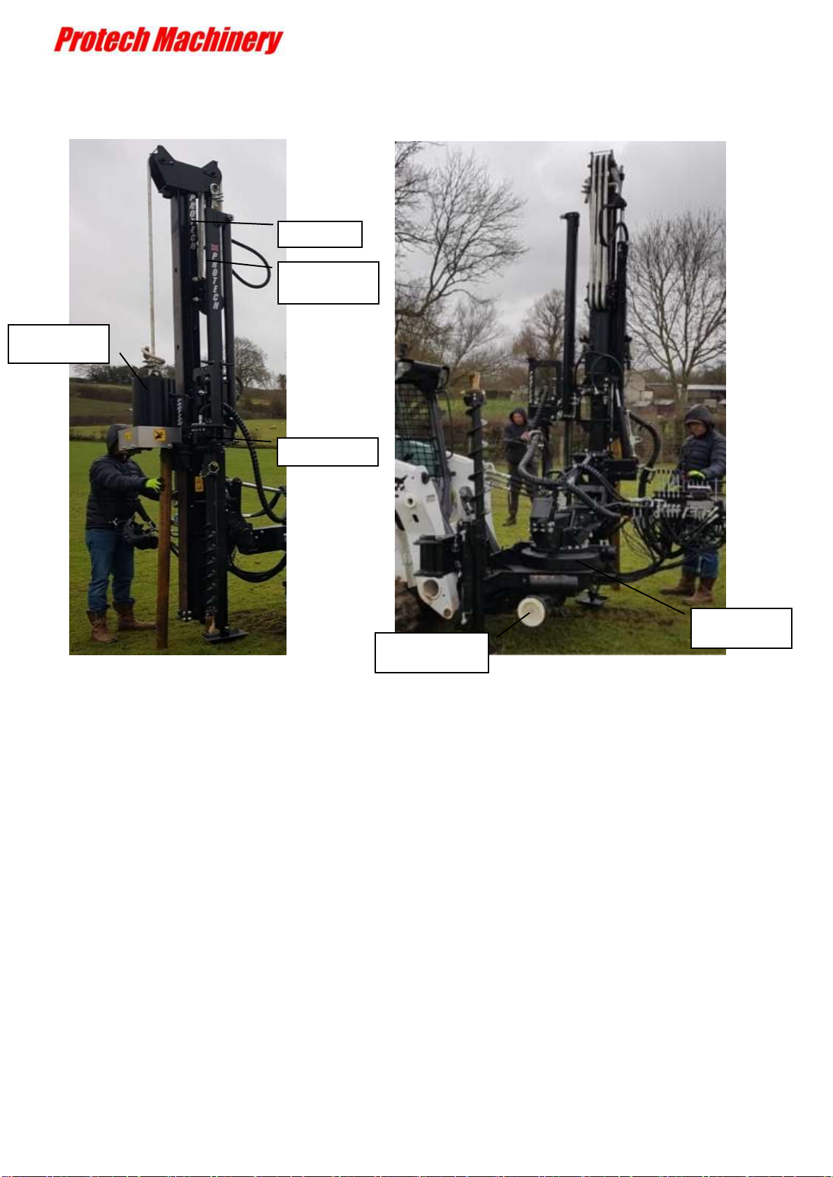
TELEMAST
ROCK SPIKE
MAST
AUGER DRIVE
HAMMER
WEIGHT
SLEW
TELE ARM
ROCK SPIKE
HOLDING PLACE

Page | 8
SAFETY STATEMENT
___________________________________________________________________
Protech Machinery Ltd are concerned for your safety and that of others around you when
operating this machinery and its associated equipment. This safety statement is our
primary way of notifying you and bringing to your attention the potential hazards
associated with the P240T and its equipment.
We advise that you follow the precautions listed throughout this manual before operation,
during operation and during routine maintenance procedures for your safety and for the
safety of others.
Protech Machinery Ltd advice that the minimum age for the safe operation of this
machinery and equipment be at least 18 years of age.
Protech Machinery Ltd also advice that a form of basic training be carried out before
operating the machinery and its equipment. This will be provided to the end user upon
receipt of the machine and its equipment. A certificate of competence will be issued on
completion of basic training.
For further training requirements please contact Protech Machinery Ltd.
Please keep all warning labels and symbols from becoming dirty or defaced so others
may be able to read and understand the hazards associated with this machine and its
equipment. When replacing parts with a warning label or symbol attached to it, please
ensure that the labels or symbols are also replaced.
Please keep this manual available at all times in the protective cover supplied with it to
prevent defacement of this manual. If I doubt about operation of this machine please
refer to this manual for guidance or contact Protech Machinery Ltd.
Failure to read and understand this manual before operation including misuse of this
machinery and equipment could lead to injuries, severe injuries with life changing
consequences or even DEATH.
Protech Machinery Ltd cannot be held liable for any injury or death caused by operator
negligence, misuse of this machinery and equipment or general breach of the standard
health and safety practices within the work place

Page | 9
SAFETY INFORMATION
___________________________________________________________________
This machine has the potential to be extremely dangerous - in the wrong hands it can
maim, cause serious injury or even kill. It is therefore imperative that both the owner and
operator of the machine reads and understands the following section to ensure they are
fully aware of the dangers that do, or may exist, and their responsibilities surrounding the
use and operation of the machine.
The operator of this machine is responsible not only for their own safety but equally for
the safety of others who may come into close proximity of the machine.
When the machine is not in use it should be parked on a firm level site and the starting
key removed.
In the event of any fault being detected with the machine operation it must be stopped
immediately and not used again until the fault has been corrected by a qualified
technician.
•Before starting the machine the operator must read and understand all aspects of
use and maintenance of the machine as stated in this manual
•The machine must only be used by a responsible adult who is familiar with all
aspects relating to safe operation
•The machine must not be operated by children or non-authorised persons
•Operators must know the meaning of all operation and safety decals on the
machine
•Operators must know the procedure for switching the machine off normally and by
using the Emergency Stop
•Do not attempt to use the machine if the Emergency Stop switch is damaged or
malfunctioning.
•Never use the machine with safety removed or defective
•Operators should practice on flat open ground to familiarise themselves with
driving and manoeuvring the machine before attempting to use it on sloping
ground

Page | 10
•Never leave a running machine unattended. Always switch the engine off and
remove the ignition key
•Always stop and switch off the machine if persons or animals enter the work area.
Do not restart the machine until they are at a safe distance.
•Never use the machine to perform a task it was not designed for.
•Never allow persons to ride on the machine.
•It is the users responsibility to protect persons in or near the work zone
•When servicing or maintaining the machine no one should be allowed beneath it
when it is raised unless it is securely supported on suitable ramps or stands.
•Never attempt to service or maintain the machine whilst it is running: always
switch off the engine and remove the starting key
•Beware of stored energy in the hydraulic circuits when the machine is switched
off.
•Always press the Emergency Stop switch before refuelling.
•Wherever possible refuel the machine before work when the engine is cold. If
refuelling during work, switch the engine off and allow to cool before adding fuel.
•Test the Emergency Stop switch before each period of work to ensure it functions
correctly.
•Never leave the ignition key in the machine control unit where it could be started
and used by unauthorised persons.
•Never stand in front of the machine when it is being operated.
•Always wear PPE (personal protective equipment)

Page | 11
POTENTIAL SIGNIFICANT DANGERS ASSOCIATED WITH THE USE OF THIS
MACHINE:
Injuring of feet. No person must be in this area when the Post Driver is raised or lowered
by the tractor or near to the rear leg and foot plate when operating this control.
Crushing under the falling weight. No person must be near the post when the weight is
falling. Never put a hand on top of the post or rock spike under any circumstances.
A trapping zone from the forward and side tilting mast, no person must be in this area.
A trapping zone between the Slew arm and Main frame, no person must be in this area.
Electrocution from Overhead Power Lines (by contact with or flashover from).
Being hit by flying debris such as splinters from wooden posts.
Injection of high pressure oil from damaged couplings or hydraulic hoses.
Misuse of hydraulic accumulator, which is filled up with 350 bar nitrogen pressure
Beware of low bridges and other overhead obstructions, always measure and be aware of
the maximum height when transporting the machine.

Page | 12
PERSONAL PROTECTIVE EQUIPMENT
___________________________________________________________________
It is advised that the following personal protective safety equipment be worn at all times
when operating this machinery.
EC Personal Protective Equipment Directive (89/686/EEC).
•Eye wear to a minimum of high energy low impact protection.
•Face shield for high energy and high impact protection, (advised).
•Hearing protectors with active noise reduction.
•Safety boots.
•High visibility clothing.
•Hard wearing safety gloves.

Page | 13
MACHINE OPERATION
BEFORE USING THIS MACHINE YOU MUST:
Ensure you read and fully understand all sections of the operator handbook,
Ensure the operator is, or has been, properly trained to use this machine.
Ensure the operator has been issued with, reads and fully understands the operator
handbook.
The post cap plate must be used to hold posts at all times. Under no circumstances should
the post be held manually while operating the Post Driver.
Only the operator must control the Post Driver, Spectators must be kept away from the
machine at all times.
Ensure that all safety guards are fitted and in good condition.
Ensure that machine fittings and couplings are in good condition.
Ensure that all warning labels are always visible and not damaged, defaced or missing
Ensure the operator is protected from noise. Ear defenders should be worn.
Ensure the operator is protected from flying debris. Safety glasses should be worn.
.
Always check for worn hydraulic components.
Always ensure the rope is not damaged. Replacements must be a certified Protech rope.
When working on sloping ground, it is far safer to drive up and down rather than across
the slope.

Page | 14
MACHINE SAFETY DECALS
Standard Triangle to indicate
Alert/Warning
Warning read Product Manual
Warning danger area from tilting mast
Warning danger of feet being crushed.
Warning eye protection must be warn
Warning ear protection must be warn
Warning Danger of falling weight
Warning Danger of overhead cables
Lubrication Point
Warning danger of fingers and hands
being crushed

Page | 15
CONTROL FUNCTIONS OF THE POST DRIVER
______________________________________________________________________
The photo below displays the layout of the control panel. Moving the control lever up or
down operates the function in the direction displayed of the Post Driver.
ROCK SPIKE
TELEMAST
LEGS
CONTROLS
MAST and
WEIGHT
CONTROLS
2-Axis AUTO
LEVEL
CONTROLS
AUGER
CONTROLS
Relief valve (will protect your
machine from excessive
skid-steer flow). Adjustable.
Check valve. Protects your
controls.

Page | 16
SLEW ARM
______________________________________________________________________
Operating the slew control lever pivots the slew arm from parallel to the main frame through
120 degrees.
As the control is mounted to the slew arm, it will move with operation of the slew control.
The operator must work in the control area of the post driver to avoid all trapping zones.
TELESCOPIC ARM
______________________________________________________________________
Operating the Telescopic control lever extends and retracts the inner slew arm through
800mm. As the control is mounted to the inner slew arm, it will move as the telescopic
control. The operator must work in the control area of the post driver to avoid all trapping
zones.
REAR LEG
______________________________________________________________________
Operating the Rear Leg control lever extends and retracts the leg and foot plate which is
powered down once the mast in position to stabilise the machine during the post driving
operation.
Feet must be kept clear from this crushing zone during operation of this control.
TRAPPING ZONE
CRUSHING ZONE

Page | 17
MAST FORWARD AND SIDE TILT
______________________________________________________________________
Operating the Mast Forward Tilt control lever pitches the mast forward and back (23
degrees forward and back from mast vertical position). This maintains a vertical mast while
on undulating ground.
Operating the Mast Side Tilt control lever pitches the mast side to side (35 degrees each
side from mast vertical position). This maintains a vertical mast while on undulating
ground.
POST-DRIVER WEIGHT CONTROL
______________________________________________________________________
Operating the Driver Weight control will immediately raise and lower the weight.
Everyone must be kept clear from this crushing zone during operation of this control.
TELEMAST CONTROL
______________________________________________________________________
This controls the telescopic mast
CRUSHING ZONE
TRAPPING ZONE
Check clearance prior tilting your mast.
Keep people away from this trapping zone during this operation.
Page | 18
ROCK SPIKE CONTROL
______________________________________________________________________
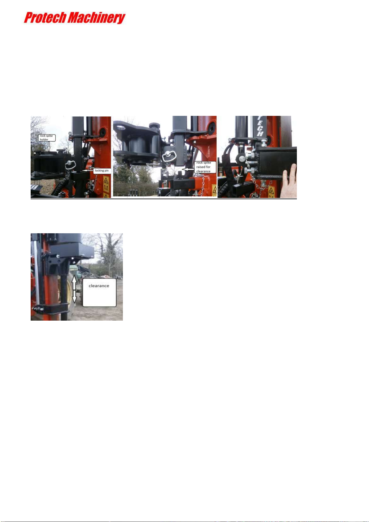
Before using the rock spike the weight will have to be raised so that the rock spike can
be moved into position.
The rock spike is located on a support pin when not in use. Raise the rock spike using
the control lever to give clearance, then manually swing into position.
The rock spike control valve is used to maintain sufficient clearance of the support collar
from the head of the rock spike.
Page | 19
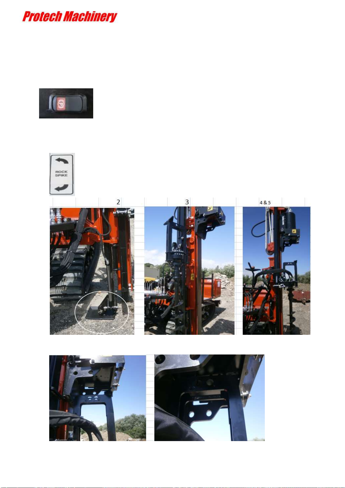
AUGER DRIVE
______________________________________________________________________
1. Put machine in `park` position.
2. Lower rear leg for stability.
3. Raise the weight.
4. Use `rock spike` lever to swing the auger into position.
5. Slowly lower the weight to lock the auger in position

Page | 20
6. Use the `Right Track` lever to rotate the drill and `Rock Spike` lever to lower the
drill
7. On completion, `right track` forward and `rock spike` up.
8. Lift the weight up clear of the auger.
9. Use the `rock spike` lever to swing the auger clear of the mast
10.AUGER CONTROLS
The recessed screw controls the hydraulic power to the auger motor.
The speed control is `clockwise` to slow down and `counter clockwise` to speed up
Table of contents
Other Protech Machinery Construction Equipment manuals

Protech Machinery
Protech Machinery P300S Product manual

Protech Machinery
Protech Machinery P10 Product manual

Protech Machinery
Protech Machinery P30 Product manual

Protech Machinery
Protech Machinery P230S Post Driver Product manual

Protech Machinery
Protech Machinery P30 Product manual

Protech Machinery
Protech Machinery P220+ Product manual
Popular Construction Equipment manuals by other brands

Putzmeister
Putzmeister BSA 1407 D5 operating instructions

IMT
IMT 5525 manual

Tesmec
Tesmec PT2450 Installation, operation and maintenance

Weber mt
Weber mt CR 8 MDM Operating and maintenance manual

TMG
TMG TMG-SDT36 product manual

PV-ezRack
PV-ezRack ComT 2.0: 5 Code-Compliant Planning and Installation Guide


