Protech Machinery P300S Product manual

0
Protech Machinery
P300S P400S
CONTRACTOR
P22 , P200S/T, P250S
Post Driver
Operator and Parts Manual
Protech Machinery Ltd,
Woolridge Farm,
Gloucester Road,
Hartpury,
Gloucestershire.
GL19 3BG Telephone: 07971 079751

1
EC DECLARATION OF CONFORMITY
Conforming to EEC Directive 98/37/EC
We Protech Machinery Ltd
Of Woolridge Farm,
Gloucester Road,
Hartpury,
Gloucestershire.
GL19 3BG
Hereby declare that the product: POSTDRIVER
Product Code P300S, P200S, P22
Serial Number series
Manufactured by the above Company complies with the required provisions of
the Directive 98/37/EC
To effect the correct application of the safety requirements stated in the EEC
Directives, the following standards and/or technical specification have been
used:
BS EN 292-1: 1991 Safety of Machinery – Basic concepts, general principals
for design – Basic terminology, methodology.
BS EN 292–2: 1991 Safety of Machinery – Basic concepts, general principals
for design – Technical principals and specifications.
BS EN 294: 1992 Safety of Machinery – Safety distances to prevent danger
zones being reached by the upper limbs.
BS 5401: 1990 Guide to information content and presentation of operator’s
manuals provided for tractors and machinery for agriculture and forestry.
Signed……………………………………………………………………………..
On behalf of Protech Machinery
Status……………………………………………………………………………….
Date…………………………………………………………………………………

2
Contents
Page number
Introduction 3
P300 Product Specification 4
P300 Part Reference 5
Safety Recommendations 6
Machine Safety Stickers 9
Control Functions of the Post Driver 10
Slew Arm Control 10
Telescopic Slew Arm Control 11
Hydraulic Rear Leg Control 12
Mast Forward Tilt Control 12
Mast Side Tilt Control 13
Driver Weight Control 13
Rock Spike Control 14
Installation Of the post Driver 15
Transportation of the Post Driver 17
Safe use of the Post Driver 17
Safe use of the Rock Spike 18
Storage of the Post Driver 20
Maintenance of the Post Driver 20
Spare Parts List
Spare Parts Illustration

3
IMPORTANT NOTICE
This manual must be read and fully understood before fitting or operating
this machine. Whenever any doubt exists please contact Protech
Machinery for assistance. If the machine is resold the Manual must be
given to the new owner.
Introduction
Dear customer,
Thank you for purchasing a Protech P300 Contractor Post Driver. Protech
machinery Ltd has produced this User Guide to assist and help you get the
most from your post driver.
This manual is line with the relevant Health and Safety regulations to assist you
with operating this machine without harm to yourself.
You should be aware that any person operating this machine with your
permission must be given adequate guidance and information to allow him or
her to use the machine safely.
Where as every effort has been made to ensure the Post Driver conforms to
Protech policy of quality, the machine cannot be expected to withstand abuse
caused by misuse and negligence by the operator.

4
P300 Contractor Product Specification
All dimensions are in millimetres.
Weight
(including rock spike)
1150
kg
Driver weight
30
0
kg
Tractor Horsepower
(minimum)
9
0 hp
Auxiliary oil flow (minimum)
5
0L/MIN
Auxiliar
y oil pressure (minimum)
1
7
0 bar
Please note: the total machine weight will vary depending on driver weight
option.

5
P300 Contractor Part References
The diagram below displays all the P300 parts referred to in this manual.

6
SAFETY INFORMATION
This machine has the potential to be extremely dangerous, in the wrong hands
it can kill. It is therefore imperative that the owner and the operator of this
machine read the following section to ensure that they are both fully aware of
the dangers that do, or may exist, and their responsibilities surrounding its use.
The operator of this machine is responsible not only for their safety but equally
for the safety of others who may come into close proximity of the machine, as
the owner you are responsible for both
POTENTIAL SIGNIFICANT DANGERS ASSOCIATED WITH THE USE OF
THIS MACHINE:
Injuring of feet. No person must be in this area when the Post Driver is raised
or lowered by the tractor or near to the rear leg and foot plate when operating
this control.
Crushing under the falling weight. No person must be near the post when the
weight is falling. Never put a hand on top of the post or rock spike under any
circumstances.
A trapping zone from the forward and side tilting mast, no person must be in
this area.
A trapping zone between the Slew arm and Main frame, no person must be in
this area.
Becoming trapped between tractor and machine when hitching or unhitching.
Machine overbalancing when freestanding (out of use).
Electrocution from Overhead Power Lines (by contact with or ‘flashover from).
Being hit by flying debris such as splinters from wooden posts.
Injection of high pressure oil from damaged couplings or hydraulic hoses.
Beware of low bridges and other overhead obstructions, always measure and
be aware of the maximum height when hitched to the tractor before
transporting.
BEFORE USING THIS MACHINE YOU MUST:
Ensure you read and fully understand all sections of the operator handbook,
Ensure the operator is, or has been properly trained to use this machine.
Ensure the operator has been issued with, reads and fully understands the
operator handbook.

7
The post cap plate must be used to hold posts at all times. Under no
circumstances should the post be held manually while operating the Post
Driver.
Only the operator must control the Post Driver, Spectators must be kept away
from the machine at all times.
Ensure that the tractor meets the minimum weight recommendations of the
machine manufacturer.
Ensure that the tractor is in correct working condition, with correct fluid levels.
Ensure that all safety guards are fitted and in good condition.
Ensure that machine fittings and couplings are in good condition.
Ensure that all warning labels are always visible and not damaged, defaced or
missing
Ensure the operator is protected from noise. Ear defenders should be worn.
Ensure the operator is protected from flying debris. Safety glasses should be
worn.
Always ensure no person is operating or on the tractor while the operator is
near to or using the machine.
Always ensure when you remove your machine from the tractor that it is left in
a safe and stable position using the stands and props provided and secured if
necessary.
Always check for worn hydraulic components.
Always ensure the rope is not damaged. Replacements must be a certified
Protech rope.
When working on sliding ground, it is far safer to drive up and down rather than
across the slopes.
During maintenance or adjustments:
Ensure that the weight is fully down, with the rope relaxed.
Ensure that the hydraulic pressure is released.
Ensure that the Tractor engine is switched off.
During Transport ensure:
That the weight is fully down
That the Post Driver is carried low to the ground and with the mast
crowded back for stability and maximum clearance from overhead
obstructions.
Always drive at a safe speed and in complete control of the vehicle.

8
WHEN NOT TO USE THIS MACHINE:
Never attempt to use this machine if you have not been trained to do so.
Never use a machine until you have read and fully understood the operator
handbook, are familiar with and practiced the controls.
Never use a machine that is poorly maintained
Never use a machine on which the hydraulic system shows signs of wear or
damage.
Never fit, or use a machine on a tractor that does not meet the manufacturers
minimum specification level.
Never start or continue to work a machine if people are nearby or approaching
– stop and wait until they are at a safe distance before continuing.
Never use a machine to perform a task it has not been designed to do.
Never operate the tractor from any other position other than from the driving
seat, especially whilst hitching or unhitching the machine.
Never carry out maintenance of a machine or a tractor whilst the engine is
running – the engine should be switched off, the key removed and pocketed.
Never leave a machine unattended in a raised position – it should be lowered
to the ground on a level firm site.
Never leave a tractor with the key in or the engine running.
Never attempt to detect a hydraulic leak with your hand – use a piece of
cardboard.
Never allow children near to, or play on, a tractor or machine under any
circumstances.
Never move the position of the control panel.
Notes
______________________________________________________________
______________________________________________________________
______________________________________________________________
______________________________________________________________
______________________________________________________________
______________________________________________________________
______________________________________________________________
______________________________________________________________
______________________________________________________________
______________________________________________________________
______________________________________________________________
______________________________________________________________
Machine Safety Stickers

9
Standard Triangle to indicate
Alert/Warning
Warning read Product Manual
Warning danger area from tilting
mast
Warning danger of feet being
crushed.
Warning eye protection must be warn
Warning ear protection must be warn
Warning Danger of falling weight
Warning Danger of overhead cables
Lubrication Point
Lifting point
Warning danger of fingers and hands
being crushed

10
Control Functions of the Post Driver
The diagram below displays the layout of the control panel. Moving the control
lever up or down operates the function in the direction displayed of the Post
Driver.
The Post driver controls are positioned to keep the operator at a safe distance
and provide good visibility of the work area. The operator must stay within a
safe working zone (defined later in this manual) around the control panel while
operating the post driver controls.
Slew Arm Control
Operating the slew control lever pivots the slew arm from parallel to the main
frame (transport position) through 120 degrees.
Slew arm
Control lever
Diverter lever pushed away for Rock Spike
Diverter lever Pulled towards for Slew

11
Ensure the Rock Spike diverter lever (if fitted) is in the pulled towards position
otherwise operating the slew control lever will operate the rock spike extractor
function.
As the control is mounted to the slew arm, it will move with operation of the slew
control. The operator must work in the control area of the post driver to avoid
all trapping zones.
Telescopic Slew Arm Control
Operating the Telescopic control lever extends and retracts the inner slew arm
through 800mm.
As the control is mounted to the inner slew arm, it will move with operation of
the telescopic control. The operator must work in the control area of the post
driver to avoid all trapping zones.
Telescopic

12
Hydraulic Rear Leg Control
Operating the Rear Leg control lever extends and retracts the leg and foot plate
which is powered down once the mast in position to stabilise the machine during
the post driving operation. Feet must be kept clear from this crushing zone
during operation of this control.
Mast Forward Tilt Control
Operating the Mast Forward Tilt control lever pitches the mast forward and back
(23 degrees forward and back from mast vertical position). This maintains a
vertical mast while on undulating ground.
Rear leg and
foot plate
Mast forward
tilt

13
Mast Side Tilt Control
Operating the Mast Side Tilt control lever pitches the mast side to side (35
degrees each side from mast vertical position). This maintains a vertical mast
while on undulating ground. Everyone must be kept clear from this trapping
zone during operation of this control.
Driver Weight Control
Operating the Driver Weight control powers the lever arm forward and back
which raises and lowers the weight. Everyone must be kept clear from this
crushing zone during operation of this control.
Rock Spike Control
Mast side Tilt

14
The rock Spike Extractor control is operated through the slew arm control
lever when the diverter lever is in the pushed away position.

15
Installation of the Post Driver.
1. The Post driver is delivered with Slew arm perpendicular to the main frame
and with the Slew lock pin fitted to lock the arm. Ensure the machine is
manoeuvred this position before unhitching from the tractor.
2. With the machine positioned on a firm level site and securely supported,
manoeuvre the tractor squarely up to the machine with the tractors link arms
set to a height level with the machines lower link brackets.
3. Connect the tractors link arms to the machine lower link brackets and retain
in position with the linkage and lynch pins supplied.
4. Connect the tractor top link (not supplied) to the machine and secure with the
linkage and lynch pin supplied. The tractor top link must be category 2 on the
machine end or conversion bush used if category 3.
5. Adjust the Tractor link arm stabilisers to centralise the Post Driver and reduce
excessive lateral sway
6. You must familiarise yourself and understand the controls and their functions;
therefore after studying the previous section practise moving the levers before
connecting any hydraulic hoses the tractor. The diagram shows the safe
working zone the operator must work in while operating the post driver controls.
All dimensions are in millimetres.

16
7. Connect the pressure and return hoses to and from the control valve to the
tractor hydraulic service.
8. Before removing the safety lock plates very carefully move each control lever
forward and back a small distance until each cylinder is able to extend and
retract slightly. Care must be taken as to not damage or strain any fabrication
with the safety lock plates in position. This procedure will prime all cylinders
with oil and remove any air trapped in the hydraulic circuit. Removing the safety
lock plates before doing so could cause the mast to fall if the cylinders are not
charged with oil.
9. Remove the safety lock plates and slew lock pin.
10. Fully operate all controls. Always raise the hydraulic rear leg and foot plate
off the ground before using the slew or telescopic control. Care must be taken
with the weight control, with the weight lifted up the mast operate the control
very carefully to slowly lower the weight. A falling weight down to the bottom of
the mast will cause damage.
11 The Post Driver is now ready for use.
Transporting the Post Driver.

17
To put the Post driver into transport position, operate the slew control to position
the slew arm parallel with the main frame (slew cylinder closed). If the rock
spike option is fitted ensure the diverter lever is pulled towards to operate the
slew function.
Fit the slew lock pin and mast forward tilt and mast side tilt safety lock plates.
Always ensure the telescopic is fully retracted and the mast tilt ram is fully
closed.
Always transport the post driver with the weight fully lower and with the front
legs fully raised so the machine is carried as low as possible on the tractor
linkage without causing obstruction
Always ensure the rock spike (if fitted) is retained with the rock spike lock pin
in the rock spike carrier.
Safe use of the Post Driver.
1. Manually start a post in the desired location so it becomes self supported.
Under no circumstances should the post be held manually while operating the
Post Driver. The Post driver controls are positioned to keep the operator at a
safe distance and provide good visibility of the work area. Under no
circumstances should the control panel position be moved and the operator
must stay within a
2. With the tractor and machine near to the work area remove to slew lock pin
and safety lock plates.
3. Drive the tractor near to the post so it can be reached while operating the
external controls. Lower the machine onto the ground so it stands on its front
legs and firmly apply the tractor handbrake. If working on a sloping ground it is
far safer to drive up and down than across the slope. Engage the auxiliary
service to provide oil flow to the control valve.
4. The operator can now enter the safe working zone. With the driver weight
fully down ensure the post cap lock chain is hooked onto the post cap chain
hook and retained with lynch pin. This connects the driver weight to the post
cap plate.
5. Operate the control to raise the driver weight and post cap plate a short
distance above the post.
6. With the hydraulic rear leg raised off the ground, operate the controls to
position the post cap plate above the post. Ensure the mast is angled to match
the desired angle of the post. With the Post driver in this position, the
operator must never put their hands on top of the post or move the post
manually.
7. Lower the rear leg and foot plate only enough to stabilise the machine. If the
front legs are raised off the ground then the rear leg has been lowered too far.

18
8. Carefully lower the driver weight and post cap plate onto the post.
9. Unhook the post cap lock chain from the post cap plate.
10. Operate the control to raise the driver weight then move the control lever
fully in the down position to drop the weight with maximum impact.
11. Repeat step 10 until the post has been driven into the ground to the desired
depth.
12. With the driver weight and cap plate lowered on top of the post hook the
post cap lock chain onto the post cap chain hook.
13. Operate the driver weight control to raise the weight and post cap plate of
the post.
14. Operate the control to raise the rear leg and foot plate off the ground.
15. Operate the Slew or telescopic control to move the mast away from the
post.
16 Carefully operate the driver weight control to slowly lower the weight and
post cap plate fully to the bottom of the mast.
17. At this position the operator can move away from the safe working zone.
17. Repeat the safe working procedure steps for each post. To transport the
post driver then ensure the transportation procedure is followed.
Safe Use of the Rock Spike.
The rock spike is an optional extra is recommended for use on stony or hard
ground and creates a pilot hole for the post.
1. Follow steps 2, 3 and 4 from the Safe use of Post Driver section.
2. Operate the weight control to carefully raise the weight and post cap plate a
short distance above the rock spike.
3. Ensure the diverter lever is pushed away so when operating the slew control
lever the rock spike ram is activated.
4. Operate the control fully retract the rock spike ram. This should slightly raise
the rock spike above the rock spike carrier.
5. Remove the rock spike lock pin.

19
6. The operator must remain in the safe working zone and push the rock spike
hinge around and underneath the post cap plate. Never push the rock spike
itself and never put hands on top of the rock spike. Pushing the rock spike hinge
keeps the operators hands and arms clear from the suspended weight and post
cap plate.
7. Operate the control to extend to the rock spike ram and lower the rock spike
onto the ground. Continue to extend the rock spike ram until the rock spike
hinge is lowered 500mm below the rock spike collar.
8. Operate the control to slowly lower the weight and post cap plate onto the
rock spike.
9. Unhook the post cap lock chain from the post cap chain hook.
10. Operate the control to fully raise the driver weight then move the control
lever into the fully down position to drop the weight.
11. Repeat step 10 to drive in the rock spike. Ensure the rock spike hinge is
lowered between hits to always ensure the hinge collar is below the rock spike
collar otherwise causing damage to the rock spike ram and fabrication.
12. Once the rock spike has been driven to the desired depth and with the driver
weight and post cap plate lowered on top of the rock spike, hook the post cap
lock chain onto the post cap chain hook and retain with lynch pin.
13. Operate the control to fully retract the rock spike ram.
14. Operate the control to raise the driver weight and post cap plate a short
distance above the rock spike.
15. The operator must remain in the safe working zone and pull the rock spike
hinge (which keeps hands and arm clear from the suspended driver weight and
post cap plate) back into the rock spike carrier and retain with the rock spike
lock pin. Never pull the rock spike itself and never put hands on top of the rock
spike.
16. Carefully operate the control to slowly lower the driver weight and post cap
plate down to the bottom of the mast.
17. At this position the operator can move away from the safe working zone.
Storage of the Post Driver
Where possible, store the Post Driver away from areas that have public access.
This manual suits for next models
4
Table of contents
Other Protech Machinery Construction Equipment manuals
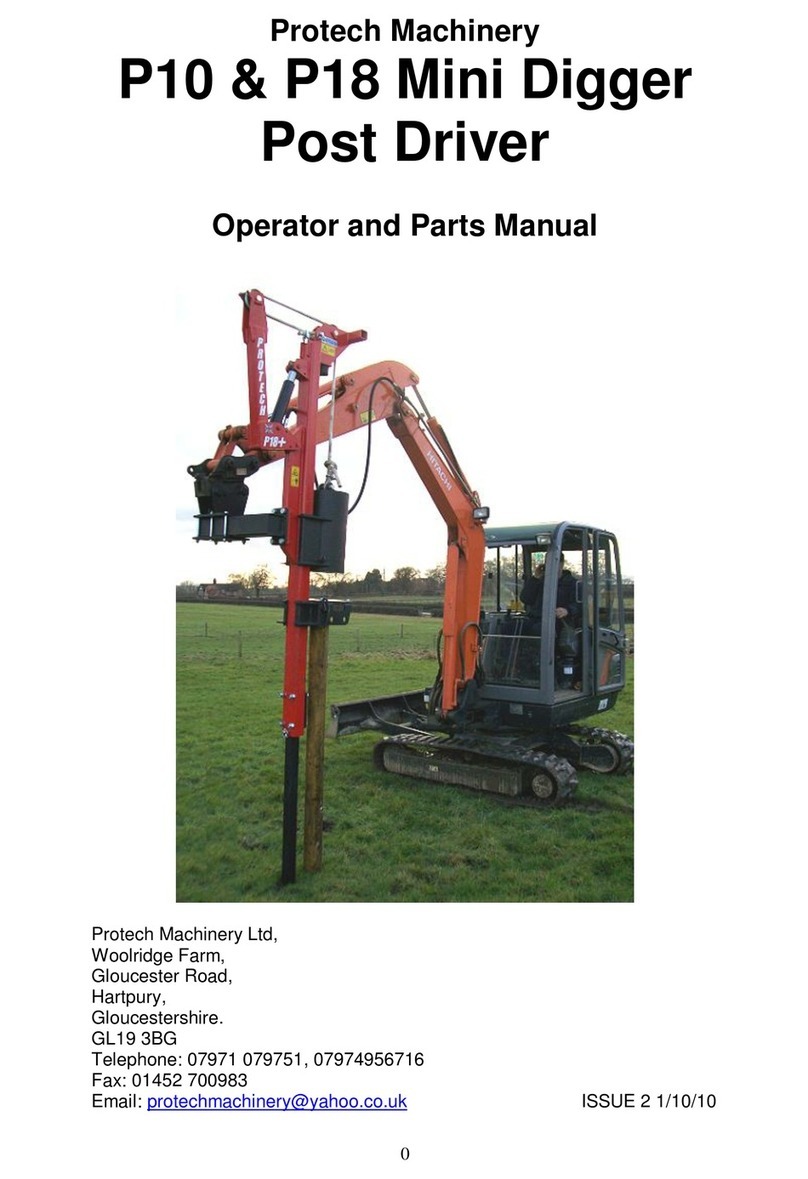
Protech Machinery
Protech Machinery P10 Product manual
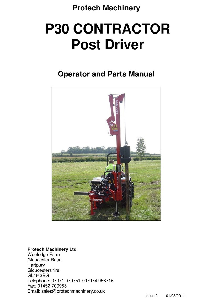
Protech Machinery
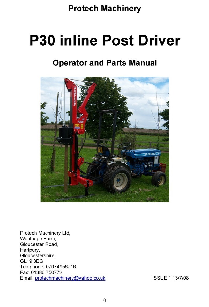
Protech Machinery P30 Product manual
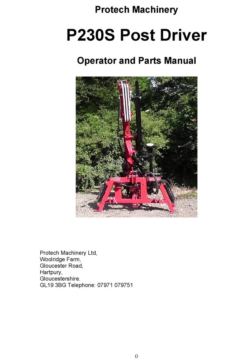
Protech Machinery
Protech Machinery P230S Post Driver Product manual
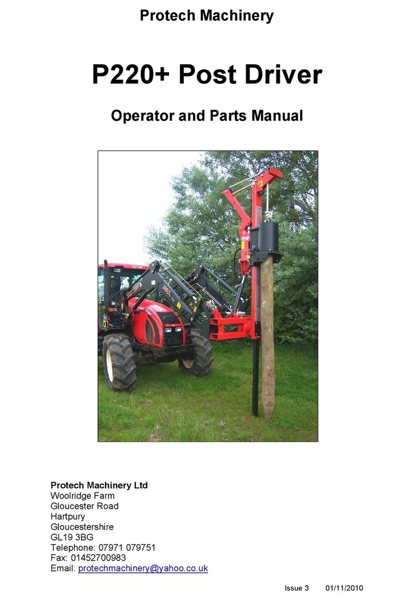
Protech Machinery
Protech Machinery P220+ Product manual
Protech Machinery
Protech Machinery P30 Product manual
Protech Machinery
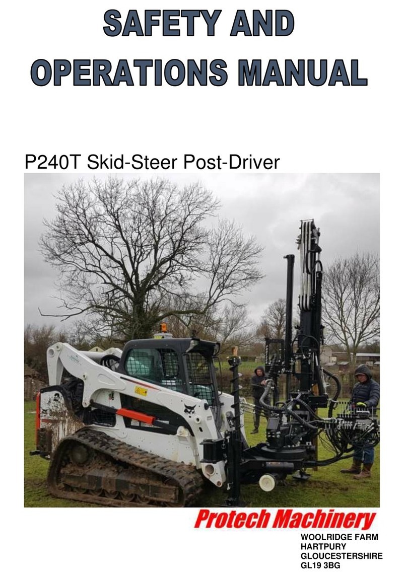
Protech Machinery P240T User manual
