Protech Machinery P30 Product manual

Protech Machinery
P30 CONTRACTOR
Post Driver
Operator and Parts Manual
Protech Machinery Ltd
Woolridge Farm
Gloucester Road
Hartpury
Gloucestershire
GL19 3BG
Telephone: 07971 079751 / 07974 956716
Fax: 01452 700983
Email: [email protected] Issue 2 01/08/2011

1
Director
30th August, 2011
EC DECLARATION OF CONFORMITY
Conforming to EEC Directive 98/37/EC
We Protech Machinery Ltd
of Woolridge Farm
Gloucester Road
Hartpury
Gloucestershire
GL19 3BG
Hereby declare that the product: POSTDRIVER
Product Code P30 CONTRACTOR
Serial Number series
Manufactured by the above Company complies with the required provisions of
the Directive 98/37/EC
To effect the correct application of the safety requirements stated in the EEC
Directives, the following standards and/or technical specification have been
used:
BS EN 292-1: 1991 Safety of Machinery –Basic concepts, general principals
for design –Basic terminology, methodology.
BS EN 292–2: 1991 Safety of Machinery –Basic concepts, general principals
for design –Technical principals and specifications.
BS EN 294: 1992 Safety of Machinery –Safety distances to prevent danger
zones being reached by the upper limbs.
BS 5401: 1990 Guide to information content and presentation of operator’s
manuals provided for tractors and machinery for agriculture and forestry.
Signed……………………………………………………………………………..
On behalf of Protech Machinery
Status……………………………………………………………………………….
Date…………………………………………………………………………………

2
Contents
Page number
Introduction
3
Product Specification
4
Safety Rules
5
Label Identification
6
Delivery and installation
7
Safe use of the Post Diver
9
Safe use of the Tele Mast
11
2nd Stage Telescopic Mast
12
Transportation of the Post Driver
13
Storage of the Post Driver
13
Maintenance of the Post Driver
13

3
IMPORTANT NOTICE
Please read this manual before fitting or operating this machine.
Whenever any doubt exists please contact Protech Machinery for
assistance. If the machine is resold the Manual must be given to the
new owner.
Introduction
Dear Customer
Thank you for purchasing a Protech P30 CONTRACTOR Post Driver.
Protech Machinery Ltd has produced this User Guide to assist and help you to
get the most from your post driver.
This manual is line with the relevant Health and Safety regulations to assist
you with operating this machinery without harm to yourself.
You should be aware that any person operating this machine with your
permission must be given adequate guidance and information to allow him or
her to use the machine safely.
Where as every effort has been made to ensure the Post Driver conforms to
Protech policy of quality, the machine cannot be expected to withstand abuse
caused by misuse and negligence by the operator.

4
Product Specification
Total Weight
600kg
Min Tractor Horsepower
From 35 HP
Max oil flow
50L/MIN
Oil pressure
150 bar
Linkage type
Cat 1
Rope Pulley
Lever Arm
Mast
side tilt ram
Pressure and
return control
hoses
Sideshift ram
Front & rear
leg lock pin
Front leg
Rear leg
Weight Rope
Mast
Driver Weight
Post Cap Plate
Mast stop
Hydraulic
mast leg ram
Mast leg
Lower link pins

5
Safety Rules
Whenever possible, warning Pictograms {Labels
without words} or warning labels are used on both
the machine near the point of danger, and in this
user manual near the relevant instructions
Before fitting the Post Driver to the Loader, it is the
operator’s responsibility to ensure the stability of
the Loader and Post Driver in all anticipated
conditions, and that the Loader is suitable for the
Post Driver.
Before using the Loader, check that it is in correct
working condition, with correct fluid levels and
correct tyre pressure.
Only the operator must control the Post Driver,
Spectators must be kept away from the machine at
all times.
The post cap plate must be used to hold posts at all
times. Under no circumstances should the post be
held manually while operating the Post Driver.
Before using the Post Driver, test the hydraulic
system for leaks. If a small leak is obvious, check
the location using a piece of cardboard. Small high
pressure leaks can penetrate the skin which need
medical attention.
During maintenance or adjustments:
Ensure that the weight is fully down, with the
rope relaxed.
Ensure that the hydraulic pressure is
released.
Ensure that the Loader engine is switched
off and the handbrake is secure on.
During Transport ensure:
That the weight is fully down
That the Post Driver is carried low to the
ground and with the mast crowded back for
stability and maximum clearance from
overhead obstructions.
Ensure that the transport lock is fitted to the
mast tilt ram.
Always drive at a safe speed and in
complete control of the vehicle.
When working on sliding ground, it is far safer to
drive up and down rather than across the slopes.
Always check for worn hydraulic components. Any
damaged rope must be replaced before failure
occurs –and must be a certified Protech
replacement.
No mast supporting components must be moved
until the mast is securely held in the vertical
position.

6
Label Identification
Where possible, warning labels are used both on the machine near the point
of danger and in this user Manual.
Standard Triangle to indicate
Alert/Warning
Warning read Product Manual
Warning danger area from tilting mast
Warning danger of feet being
crushed.
Warning eye protection must be warn
Warning ear protection must be warn
Warning Danger of falling weight
Warning Danger of overhead cables
Lubrication Point
Lifting point

7
Delivery and installation of the Post driver.
If the Post Driver has been delivered on a pallet then follow this assembly
procedure. To unload the pallet from the delivery lorry you will need a
minimum 1 ton lift capacity loader with pallet tines. Position the pallet onto
level and hard ground.
1. Using a loader with a 1 ton minimum lift capacity and with pallet tines,
attach a lifting sling (minimum 2 ton lifting sling) around the mast of the
post driver and onto both pallet tines of the loader as shown.
Raise the loader just so the lifting sling becomes taut.
2. Remove all banding which strapped the post driver to the wooden
pallet.
3. To connect the mast tilt ram, carefully raise the loader to tilt the mast.
Once the mast tilt ram holes are aligned then fit the mast tilt ram pin.
Never put your fingers through these holes to align the pin. If the
control panel is not attached then bolt the control panel with the
mounting bolts supplied.
Mast tilt ram pin
Mast tilt ram
Control Panel
Control bracket
Mounting bolts

8
4. Carefully raise the loader to lift the Post driver off the ground and
remove wooden pallet.
5. All legs must now be levelled. With the post driver still raised off the
ground connect the pressure and return control hoses to the tractor.
Be careful not to stretch these hydraulic hoses.
6. Operate the rear leg control lever which will raise and lower the mast
leg. Carefully lower the loader to rest the post driver onto the ground
and operate the rear leg so all legs are level and touching the ground.
This will make the machine level and stable. With the post driver on
the ground remove the lifting sling and disconnect the pressure and
return control hoses from the tractor.
7. Backshift option is available which travels at 90° to the sideshift and
parallel to the fenceline allowing forward & backward adjustment.
The post driver is now ready to be attached to the tractor.

9
Safe use of post driver
1.
Before the Post Driver is used,
ensure that every single person who
works with or works close to the post
driver reads and understands this
manual.
2.
Ensure that all Personnel working
near to the post driver must wear
protective clothing, i.e. Eye and Ear
defenders, strong safety boots and
gloves.
3.
There is a danger of injuring feet
under the foot, so no person must be
in this area when the Post Driver is
raised or lowered by the Loader.
4.
There is a danger from crushing
under the falling weight. No person
must be near the post when the
weight is falling. Never put a hand on
top of the post under any
circumstances.
5.
Be aware of overhead cables
6.
There is a danger of the mast tilting
and creating a trapping zone, no
person must be in this area.
7. Reverse the Tractor to the Post Driver and attach the lower link arms to
the link brackets on the Post Driver. Fit the supplied pins and securing
lynch pins.
8. Connect the Pressure and return control hoses to the tractor hydraulic
service.
9. Operate the mast side tilt control lever to work the hydraulic top link.
Extend the hydraulic top link to align with the top link mounting hole of
the tractor and fit top link pin and secure with lynch pin.

10
10.Adjust the Tractor link arm stabilisers to centralise the Post Driver and
reduce excessive lateral sway.
11.Raise the tractor links arms to raise the post driver of the ground and
remove the stabilising leg stand.
12.For the first use of the post driver, carefully operate all control levers to
clear any air that might be trapped in the hydraulic system.
13.Manually start a post in the desired location so it becomes self
supported. Make sure the tractor and post driver are at a safe distance
away from the manual process.
14.Make sure the Post Cap chain on the side of the Post cap is hooked
onto the driver weight and secured with the lynch pin. Then drive the
tractor and post driver into position with the weight and post cap raised
a short distance as to clear the top of the post. Never put your hand
on top of the post cap plate or underneath the driver weight.
15.Once in position and with the hydraulic rear leg in the fully closed
position fully lower the post driver on the tractors linkage until the front
legs are resting on the ground. For uneven ground the front leg lock
pin can be removed which allows the front legs to pivot and rest more
level. The Tele arm, Mast forward tilt and mast side tilt control levers
can be operated to align the machine with the post. Once at the
desired position, operate the rear leg control lever to lower the mast leg
onto the ground and stabilise the machine.
16.Carefully lower the post cap and driver weight onto the post and
release the post cap plate by unhooking both post cap chains.
17.With all persons at a safe distance from the post driver, operate the
weight control lever to raise weight and then lower, allowing the weight
to fall to hit the post
18.Raise and drop the weight until the driven position of the post has been
achieved.
19.Never drop the weight with the post cap resting on the mast stop. This
will cause damage to the machine.
20.Once at the driven position then connect the post cap back onto the
driver weight using the post cap chain and secure with lynch pins.
Carefully raise the driver weight and cap plate off the post using either
the weight control lever. Then drive the tractor and post driver away
from the post. Once clear of the post fully lower the weight. Do not
drive around with the driver weight raised up in the air.
NEVER PUT HANDS ON TOP OF THE POST
UNDER ANY CIRCUMSTANCES.

11
Safe Use of Telescopic Mast Option
1. The Telescopic Mast option enables up to 12 foot posts to be driven in the
ground.
2. Operate the Tele Mast lever to familiarise yourself with this function. This
will raise and lower the mast.
3. Depending on the post height, operate the Telescopic Mast ram to raise
the Mast clear of the post.
4. Carefully lower the post cap and driver weight onto the post and release
the post cap plate by unhooking both post cap chains.
5. With all persons at a safe distance from the post driver, raise the driver
weight then move the Tractor valve to exhaust the system, allowing the
weight to fall to hit the post.
6. Raise and drop the weight until the driven position of the post has been
achieved.
7. Never drop the weight with the post cap resting on the mast stop. This will
cause damage to the machine. Always lower the telescopic mast first to
give distance (minimum 300mm) between the post cap and mast stop.
8. Once at the driven position then connect the post cap back onto the driver
weight using both post cap chains and secure with lynch pins. Carefully
raise the driver weight and cap plate off the post using either the lever ram
or telescopic mast ram. Then drive the tractor and post driver away from
the post. Once clear of the post fully lower the telescopic mast and lever
ram. Do not drive around with the driver weight raised up in the air.
Telescopic Mast raised
up and down
NEVER
PUT HANDS ON TOP
OF THE POST
UNDER ANY
CIRCUMSTANCES

12
2nd stage Telescopic Mast
1. Fully raise the telescopic mast, then fit the mast lock pin through the
inner mast hole and secure with the lynch pin.
If there are multiple holes in the inner mast then always use the
uppermost hole.
2. Carefully lower the telescopic mast onto the pin just enough to carry
the weight of the mast. Do not power down onto the pin.
3. Turn off the tractor and operate the telescopic ram to relieve any
pressurised oil; then remove the telescopic ram pin. Restart the tractor
and retract the telescopic ram to align with the 2nd stage mounting
holes. Never ever use your finger to align the holes. Once the
holes are aligned re fit the telescopic ram pin.
Raise the telescopic mast and remove the mast lock pin. The post
driver is now ready for use. To adjust back to the 1st position apply the
same procedure. Never remove post driver from the tractor with the
mast in the 2nd stage position.
Inner mast
Mast lock pin
Telescopic ram
pin
2nd stage
telescopic mount
This position is only used for tall posts (12ft and over)
such as for deer fencing

13
Transportation of the Post Driver.
Always lower the weight and release any hydraulic pressure.
Always carry the Post Driver on the Tractor Linkage as low as possible but
without hitting the ground.
Storage and unhitching the Post Driver
Before unhitching from the tractor always fit the stabilising leg stand & front
leg locking pins and secure with lynch pins.
Where possible, store the Post Driver away from areas that have public
access
Store the Post Driver on level, stable ground.
Lower the weight and release any residual hydraulic pressure.
Store the hydraulic hose in a clean, secure place.
The Post Driver must be stored in a position to be easily reconnected to
the tractor.
Maintenance of the Post Driver
Daily
Check weight rope for any signs of wear. If in doubt, change the rope.
Check hydraulic hoses for any signs of wear. If in doubt change the hose.
Grease rope pulleys.
Apply grease to the face of the mast.
Weekly
Check the hydraulics for leaks.
Grease all arm pivots.
Check the rope pulleys turn freely.
Check all pivots for wear.
Other manuals for P30
1
Table of contents
Other Protech Machinery Construction Equipment manuals
Protech Machinery
Protech Machinery P240T User manual
Protech Machinery
Protech Machinery P300S Product manual
Protech Machinery
Protech Machinery P230S Post Driver Product manual
Protech Machinery
Protech Machinery P220+ Product manual
Protech Machinery
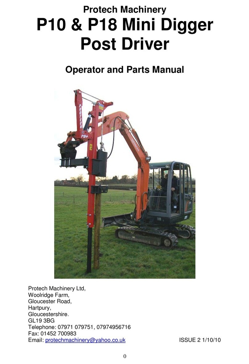
Protech Machinery P10 Product manual
Protech Machinery
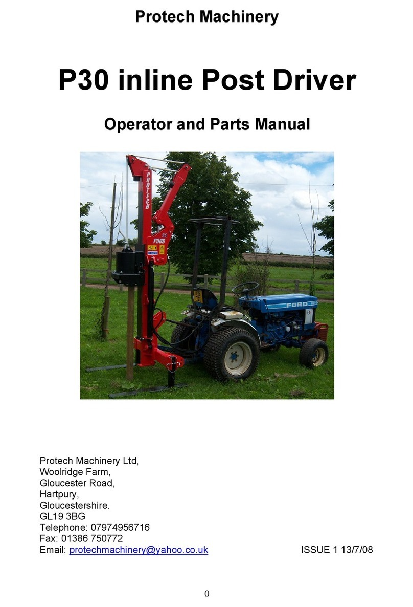
Protech Machinery P30 Product manual


