Protect America Peacekeeper User manual

1
O W N E R ' S M A N U A L
T h e P e a c e k e e p e r
V e r s i o n 3 a n d l a t e r

FCC Notices
FCC Part 15 Information to the User
Changes or modifications not expressly approved by Interlogix, Inc. can void the user’s authority to operate the equipment.
FCC Part 15 Class B
This equipment has been tested and found to comply with the limits for a Class B digital device, pursuant to part 15 of the FCC Rules. These
limits are designed to provide reasonable protection against interference in a residential installation.
This equipment generates, uses, and can radiate radio frequency energy and, if not installed and used in accordance with the instructions,
may cause harmful interference to radio communications. However, there is no guarantee that interference will not occur in a particular
installation.
If this equipment does cause harmful interference to radio or television reception, which can be determined by turning the equipment off and
on, the user is encouraged to try to correct the interference by one or more of the following measures:
• Reorient or relocate the receiving antenna.
• Increase the separation between the equipment and receiver.
• Connect the affected equipment and the panel receiver to separate outlets, on different branch circuits.
• Consult the dealer or an experienced radio/TV technician for help.
FCC Part 68
This equipment complies with part 68 of the FCC Rules. Located on this equipment is a label that contains, among other information, the
FCC registration number and the ringer equivalence number (REN) for this equipment. If requested, this information must be provided to the
telephone company.
The REN is used to determine the maximum number of devices that may be connected to your telephone line. In most areas, the sum of all
device RENs should not exceed five (5.0).
If this equipment causes harm to the telephone network, the telephone company may temporarily disconnect your service. If possible, you
will be notified in advance. When advance notice is not practical, you will be notified as soon as possible. You will also be advised of your
right to file a complaint with the FCC.
Your telephone company may make changes in its facilities, equipment, operations, or procedures that could affect the proper operation of
your equipment. You will be given advanced notice in order to maintain uninterrupted service.
If you experience trouble with this equipment, please contact the company that installed the equipment for service and repair information.
The telephone company may ask you to disconnect this equipment from the network until the problem has been corrected or you are sure that
the equipment is not malfunctioning.
This equipment may not be used on coin service provided by the telephone company. Connection to party lines is subject to state tariffs.
Certification Number: B4Z-USA-46042-AL-T
Service
If you have any questions about your security system or if you ever need service, please contact your security dealer.
Company Name Protect America Inc.
Phone Number 1-800-951-5111
Monitoring Phone Number 1-800-482-9800
©2002 GE INTERLOGIX, INC.
ITI is a registered trademark of GE Interlogix, Inc.
Specifications are subject to change. Some features are optional.
For reprints, order manual 466-1971 Rev A Dated April 2002

3
TABLE OF CONTENTS
Introduction. . . . . . . . . . . . . . . . . . . . . . . . . . . . . . . . . . . . . . . . 4
Security System Beeps, Lights, and Messages . . . . . . . . . . 5
How to Use Your Control Panel . . . . . . . . . . . . . . . . . . . . . . . . 7
How to Use Your KeyChain Touchpad . . . . . . . . . . . . . . . . . 8
Programming Your System . . . . . . . . . . . . . . . . . . . . . . . . . . 8
Step by Step Programming . . . . . . . . . . . . . . . . . . . . . . . . . . 10
System Tests & Trouble Beeps . . . . . . . . . . . . . . . . . . . . . . . 11
Battery Replacement . . . . . . . . . . . . . . . . . . . . . . . . . . . . . . . 13
Your Emergency Evacuation Floor Plan. . . . . . . . . . . . . . . . 14
Certificate of Installation . . . . . . . . . . . . . . . . . . . . . . . . . . . . 15
Index. . . . . . . . . . . . . . . . . . . . . . . . . . . . . Inside of Back Cover
Quick Reference Table . . . . . . . . . . . . . . . . . . . . . . Back Cover
Important Messages to the Owner:
In the following paragraphs there may be some terminology that you are not familiar with. Return to this section after you famil-
iarize yourself with your security system.
Arming Your System with Doors or Windows Open: Any sensors that are open when the system is armed will be bypassed after
the exit delay has expired. This means they will not be protecting your home. If you wish to bypass a sensor after you have armed
your system, you must first disarm the system, then open the door or window you want bypassed. Your system will tell you if a
protected door or window is open when you arm the system.
CAUTION! If you use the Control Panel to arm your security system when leaving your home, be aware of the following:
You must exit before the end of the delay period or an alarm will sound. Remember, when arming you will hear 2, 3, or 4 beeps
at the beginning of the exit delay (see page 5 of this manual to determine the meaning of control panel/system beeps). At the
end of the exit delay, the system beeps 2, 3, or 4 additional beeps. If you exit at that time (after the exit delay), your system as-
sumesyou arenow returning to your home. The systemis nowcounting down the entry delay time and will expect you todisarm
the system within the entry delay time or it will go into alarm.
Something may have happened while you were away! If you enter your home and hear alarm sirens or notice the SYSTEM
STATUS button is blinking, an intruder may be inside or another emergency may have occurred. Leave immediately, and call for
non-medical emergency help.
Canceling Accidental Alarms: You have up to 60 seconds after causing an accidental alarm to disarm your security system. If
the programmed seconds have passed, you must call the central monitoring station to cancel the alarm.
Notices for UL-Listed Installations:
• This system is suitable for Grade A household burglary applications.

4
Introduction to Your System
Your security system uses wireless technology to warn your
family about intrusion.
The system is designed to be monitored and/or to send mes-
sages to a numeric pager.
The security system uses devices called sensors which use
radio waves to communicate alarms to the Control Panel.
The system is supervised, meaning that the Control Panel
checks the status of each sensor to detect problems. If the
Control Panel detects trouble it will notify you with beeps and
indicator lights on the Control Panel itself.
Typical Security System Components
A typical security system installation may consist of the follow-
ing devices:
Control Panel
The Control Panel is used to operate and program your secu-
rity system. It communicates to you through panel voice mes-
sages, panel beeps, and by lighting buttons on the Control
Panel. The Control Panel can communicate to a central mon-
itoring station and/or a numeric pager.
KeyChain Touchpads (Optional)
KeyChain Touchpads are used to control the security system
from within or near the outside of your home.
Indoor Motion Sensors
Indoor Motion Sensors detect motion. They are used for intru-
sion protection.
Door/Window Sensors
Door/Window Sensors detect the opening of a door or win-
dow.
Door/Window Sensors
Keychain
Touchpad
(Optional)
Motion Sensor
Control Panel
w/Table Base
7KH3HDFHNHHSHU

5
Security System Beeps, Lights, and Messages
Your security system communicates to you through the use of panel voice messages, panel beeps, indicator lights on the panel
and to a numeric pager if programmed.
You communicate to your security system with key presses on the Control Panel or KeyChain touchpads. Disarming and pro-
gramming require you to input a 4-digit access code. The Master Access Code default is 1-2-3-4 when the security system
is shipped from the factory. You should change it to a code known only by you.
Panel Voice Messages
When you press the buttons on the Control Panel or a touchpad, the Control Panel responds with voice messages. Panel voice
can be enabled or disabled (see “What You Can Change:”on page 8).
These messages may respond with system information or prompt you to take further action. For example, if you want to disarm
the system and you press the DISARM button, the Control Panel responds by saying, Please enter your access code.
If you press a button and thefeature has not been programmed into the Control Panel, the panelvoice will respond with Function
not available.
Panel Beeps
Panel beeps are used to indicate key presses, status, and problems with the system. Panel beeps can be enabled or disabled
(see “What You Can Change:”on page 8).
Note: You may receive a different number of panel beeps if buttons are pressed quickly.
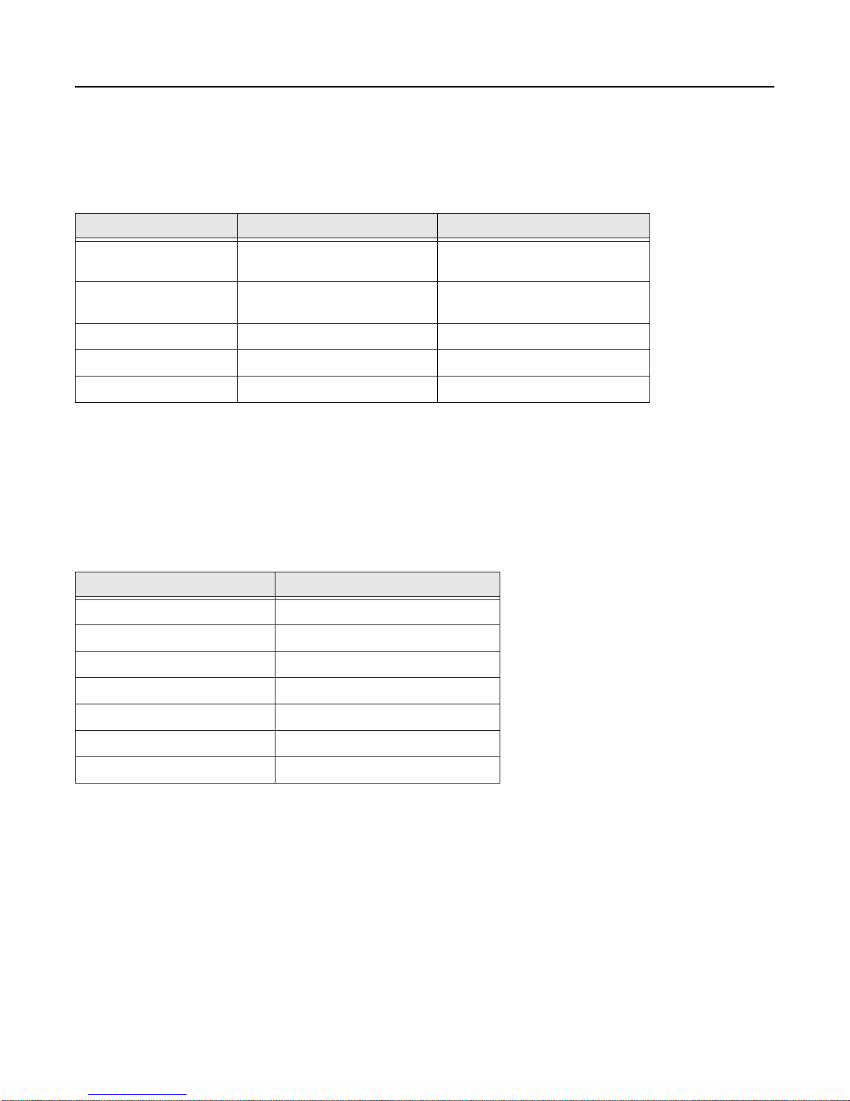
Use the following table to understand the beeps used by the security system.
Table 1: Panel Beeps
Activity Beep Response
ARM Doors & Windows Exit delay and Entry delay beeps sound 2 times every 5 seconds and 2 times per second
during the last 10 seconds (if Silent Exit is used, the Exit delay beeps will only sound twice
when you arm and twice when the exit delay expires).
ARM Motion Sensors Exit delay and Entry delay beeps sound 3 times every 5 seconds and 3 times per second
during the last 10 seconds (if Silent Exit is used, the Exit delay beeps will only sound three
times when you arm and three times when the exit delay expires).
ARM Doors/Windows &
Motion Sensors Entry delay beeps sound 4 times every 5 seconds and 4 times per second during the last
10 seconds (if Silent Exit is used, the Exit delay beeps will only sound four times when you
arm and four times when the exit delay expires).
DISARM 1 beep
CHIME DOORS 2 beeps (feature must be programmed by installer)
Trouble Beeps 6 beeps every minute. Press SYSTEM STATUS button twice to stop beeps for 4 hours
6
Security System Beeps, Lights, and Messages (Continued)
Panel Indicator Lights
Numeric Pager
You may program your security system to send a numeric message indicating system activities to your pager. The system will
send the message twice.
Use the following table to understand the panel indicator lights.
Table 2: Panel Indicator Lights
Button When the Button Light is On When the Button Flashes
ARM Doors & Windows Doors/Windows armed Doors/Windows armed &
No Entry Delay on
ARM Motion Sensors Motion Sensors armed Motion Sensors armed &
Latchkey on
DISARM System disarmed System subdisarmed
SYSTEM STATUS System trouble or Open Sensor System in alarm
CHIME Doors Door will cause chime _____________________
Use the following table to determine what the numeric message is reporting.
Table 3: Numeric Pager Reporting
Reports Numeric Message
Phone Test -101 -101
Latchkey -104 -104
Panic Code -106 -106
Disarming -110 -110
Arming -111 -111
Fail to Disarm -112 -112
Fail to Arm -113 -113
7
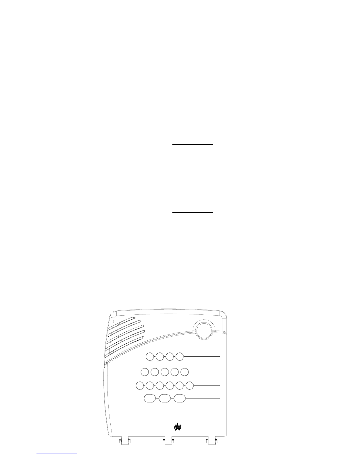
How to Use Your Control Panel
The Control Panel interface consists of 4 rows of buttons. They are: HOME SECURITY, CODE, CHIME DOOR and EMER-
GENCY.
HOME SECURITY
ARM Doors & Windows. Press once to turn the secu-
rity system protection on for all protecteddoors and windows.
If a door or window is open when you arm the system, it will
be bypassed, meaning not protected. TheSYSTEM STATUS
light will be lit.
Press twice to eliminate the preprogrammed entry delay. The
ARM Doors & Windows button blinks when No Entry Delay is
on.
ARM Motion Sensors. Pressoncetoturnprotection on
for all intrusion Motion Sensors. Use when no one is home.
This is usually used in combination with ARM Doors & Win-
dows.
Press twice to activate Latchkey. Latchkey is used to notify
parents if children do not arrive home at a predetermined time
and disarm the system. The ARM Motion Sensors button
blinks when Latchkey is on. A pager is required for this func-
tion.
DISARM. Press once and enter your access code using the
CODE buttons to turn security protection off. Some sensors,
for example smoke detectors and panic devices, are still ac-
tive even when the system is disarmed.
SYSTEM STATUS. Press to hear information about
your system. If the button is lit, there isa problem with the sys-
tem. If the button is blinking, an alarm has occurred. Press the
button to hear what is wrong with the system. See “System
Tests & Trouble Beeps” on page 11.
CODE
There are 5 CODE buttons on the Control Panel. Eachbutton
represents 2 numbers. The left CODE button is 1 - 2 which
means that this button is pressed when entering either1 or 2.
For example, if your access code is 1-2-3-4 you must press
the 1 - 2 button twice and the 3 - 4 button twice.
If your system includes 24-hour protection sensors on items
suchasgunor jewelrycases,youmustsubdisarm theControl
Panel before accessing these areas to avoid causing an
alarm. To subdisarm the system when it is already disarmed,
enter the master access code. The DISARM button will flash
when the Control Panel is subdisarmed.
CHIME Doors
Press to cause the Control Panel to beep when protected
doors or windows are opened.
This is a nice feature to use if you’re busy in one part of
your home and you want to know when family members
are going in and out of your home.
NOTE: If this button is pressed and a sensor is not associated
(programmed) with this feature the Control Panel will say,
Function not available.
EMERGENCY
POLICE. Press the POLICE button for 2 seconds (or twice
quickly) to call the central monitoring station and notify them
of a non-medical call for help.
AUXILIARY. Press either AUX button to sound a non-med-
ical auxiliary alarm.
System
Status
Doors &
Windows Motion
Sensors
Arm Disarm
9 / 05 / 63 / 4 7 / 81 / 2
Doors
Chime
AUXAUX
Test Weekly
POLICE
C O D E
E M E R G E N C Y
H O M E S E C U R I T Y
7KH3HDFHNHHSH
U

8
Programming Your System
What You Can Change:
Options:
Press Add in the START MENU and follow the voice prompts
to turn an option on.
Press Delete in the START MENU to turn an option off.
Option 01 - Panel Beeps
Panel Beeps are any beeps (including chime beeps) that
come from the Control Panel. Panel Beeps, except for
alarm sirens, may be disabled (See the “Panel Beeps”
table on page 5).
Option 02 - Panel Voice
Panel Voice may be disabled, except for status messages,
open sensor responses, and when in program mode.
Option 03 - Latchkey Time
Adding this option allows you to program Latchkey Time.
Latchkey is used to notify parents if children do not arrive
home at a predetermined time and disarm the system.
Requires a pager.
Option 41 - Chime Voice
The Control Panel will verbally announce which chime sen-
sor has been tripped if the chime feature is on.
Option 42 - Speaker Level
When this option is turned on, you can set the panel
speaker level from 1 (lowest) to 8 (highest). when this
option is turned off, the speaker level is set to 8.
Option 55 - Status Sounds
Adding this option allows you to set the volume for status
sounds, such as: arming beeps, trouble beeps and status
beeps. The lowest volume setting is 1 and the highest is
10. Deleting this option, sets the volume for status sounds
to the default setting of 7.
The Control Panel will call the pager to indicate:
•Phone Test - A phone test report is called in when a
phone test has been performed.
•Disarming - A disarming report is called in when the
system is disarmed. This option is programmed by your
installer.
•Arming - An arming report is called in when the system
is armed. This option is programmed by your installer.
•Fail to Disarm - A fail to disarm report is called in when
the system is not disarmed by the time programmed by
the installer.
•Fail to Arm - A fail to arm report is called in when the
system is not armed by the time programmed by the
installer.
•AC Power Failures - An AC power failure is called in 15
minutes after loss of power.
KeyChain Touchpad
LOCK Press once to arm doors and windows.
LOCK Press twice to arm doors, windows, and Motion Sensors.
LOCK Press 3 times to arm doors, windows, Motion Sensors, and to activate the
Latchkey option.
Entering your home If your installer programmed the KeyChain Touchpad with no entry
delay, and you armed the system with the KeyChain Touchpad, you must disarm your
system from outside of the home to avoid causing an alarm.
Exiting your home You have at least 5 seconds and up to 254 seconds(depending on
installer programming) to leave without causing an alarm.
LOCK and UNLOCK Press both buttons simultaneously for 3 seconds to send a non-
medical emergency alarm to the central monitoring station.
UNLOCK Press to disarm your security system.
For any keypress on the KeyChain Touchpad, hold the button until the indicator
light blinks.
How to Use Your KeyChain Touchpad (Optional)
KeyChain touchpads are used to control the security system from any location within or near your home.

9
•AC Power Restoral - A restoral will be reported when
power is restored.
•Alarms - Alarm reports include: Intrusion (Police), Auxil-
iary, and panic access code alarms.
Sensor Test or Phone Test . A sensor test or phone
test can be performed by following the instructions given in the
section labeled “Manual Tests--What You Need to Test”on
page 11 of this manual.
Access Codes. Your security system has a master
access code, access codes 1-5, and a panic code. The mas-
ter code is used for disarming and programming your system.
Access codes 1-5 are generally used for children or as tem-
porary codes for a babysitter or service personnel and may
be used only for disarming. The panic code may be entered
to disarm or subdisarm the system in a non-medical emer-
gency situation. The Control Panel will call the central station,
but there will be no indication of an alarm at the Control
Panel.
Note: Because different codes can be entered using the
same button presses you have to use caution when program-
ming the panic code. You need to ensure that the panic code
does not use the same button presses as other access
codes. For example if the master code is 1234, do not pro-
gram the panic code to be 2244. The Control Panel would
interpret these codes to be the same code.
Set Clock. If the panel loses power, the clock must be set.
Programming Using Panel Decal
The programming decal is visible when you open the Control Panel cover. This decal is designed to make system programming
easier for you. Always begin by choosing a button from the START MENU. Follow the voice prompts and flow arrows to com-
plete the desired task. Notice the button flow diagrams under Instruction Summary to the lower left of the buttons.
32
987
10
654
Test
by a qualified technician
System should be checked
422-3090 Rev A
Set
Access
Code Clock
Delete
prompting.
press
Delete
-
+
Hours +
To delete an option or access code
Hold key or press
and follow the voice
repeatedly until you
hear the desired item.
Note:
Cancel
Test
and
Cancel
DONE
Minutes
See Note
DONE
, then
If you make a mistake or want to
Sensor or Phone Test
follow the voice prompting.
To select a test, press
start over press
at least every three years.
Delete
START MENU
Add
Version 3
MAIN MENU
Remote
Sensor/
*
Option #
*
-
DONE
information.
Panel Beeps
Panel Voice
Option #1:
Instruction
Add Option
Summary
Add
Press
Clock Set
Press
Set Clock
Chime Voice
Latchkey Time
Add
See Note
Option #
Press
Option #42:
Option #43:
Option #55:
Option #41:
Option #3:
and follow voice prompts.
Pager Phone Number
Speaker Volume
Status Beep Volume
Option #2:
Press for program
*
use red numbers to enter 4-digit code.
Add Access Code
Hours
Access Code
See Note
Minutes
Cancel
Programming Your System (Continued)
10
Step by Step Programming Instructions
Use the following instructions to access the programming buttons and programming decals.
1. Open the Control Panel Cover by pressing the plastic
latch on the top of the Control Panel.
When you open the cover you will immediately be
prompted by the Control Panel voice to use the num-
bered keys to enter your ID.
2. Enter Your Access Code.
The Master access code is 1-2-3-4 when the panel is
shipped. You should change it to a code known only
by you.
3. The system voice will prompt you to begin with the
START MENU. The START MENU is located on the left
side of the upper decal.
The START MENU includes the following buttons:
Add
Delete
Cancel
Test
Clock Set
Press the appropriate button.
4. After pressing a button on the START MENU the system
voice will prompt you to then use the MAIN MENU.
The MAIN MENU includes the following buttons:
Option #
Sensor/Remote
Access Code
Press the appropriate button.
Depending onthe button you pressed,the system will prompt
you to continue by pressing other buttons on the panel.
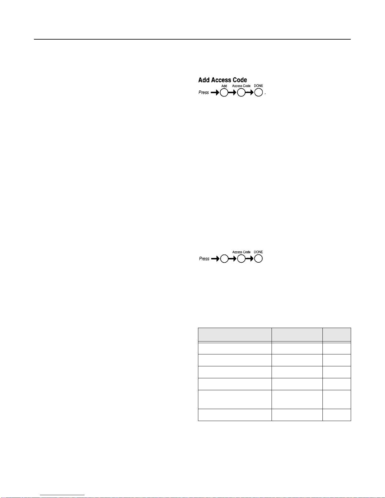
How to Change an Access Code
1. Open the cover of the Control Panel.
2. The panel voice prompts you to Use numbered keys to
enter ID. Enter your master access code using the red
numbered keys.
3. The panel voice prompts you to Please select from
START MENU. Press the Add button on the START
MENU.
4. The panel voice prompts you to Select from MAIN
MENU. Press the Access Code button on the MAIN
MENU.
5. The panel voice responds with Master Code, press again
for next access code, DONE to select or CANCEL to
quit. Press the access code button again to hear the next
access code. When you hear the access code you wish
to change press the DONE Button.
6. Enter 4 new numbers using the numbered keys.
7. Close the Control Panel cover.
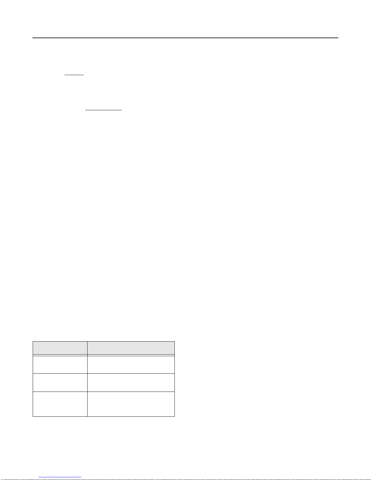
How to Delete an Access Code
1. Open the cover of the Control Panel.
2. The panel voice prompts you to Use numbered keys to
enter ID. Enter your master access code using the red
numbered keys.
3. The panel voice prompts you to Please select from
START MENU. Press the Delete button on the START
MENU.
4. The panel voice prompts you to Select from MAIN
MENU. Press the Access Code button on the MAIN
MENU.
5. The panel voice responds with the Master Code, press
again for next access code, DONE to select or CANCEL
to quit. Press the access code button again to hear the
next access code. When you hear the access code you
wish to delete, press the DONE Button. The panel
voice responds with Access Code X deleted.
6. Close the Control Panel cover.
Options
The following is a table of options you can change. See “What
You Can Change:”on page 8 for a description of these op-
tions.
Table 4: Options
Option # Add Delete
01 - Panel Beeps On Off
02 - Panel Voice On Off
03 - Latchkey Time 12am - 11:59 pm Off
41 - Chime Voice On Off
42 - Speaker Level 1 - 8 8 (high-
est)
55 - Status Beep Volume 1 - 10 10
t h e n u s e n u m b e r k e y s t o e n t e r c o d e
8988G45B.DS4
Delete Access Code
Delete

11
Automatic Control Panel Testing--What the
System Tests for You
Your security system is able to automatically test itself for:
•Power failures
•Low batteries
•Non-working sensors
•Communication troubles with the Central Monitoring Sta-
tion
Trouble Beeps. When your security system detects one
of the problems above, interior sirens sound trouble beeps
rapidlysixtimes,andthenagaineveryminute,untilthetrouble
condition is corrected.
If you do a status check by pressing the SYSTEM STATUS
button twice or change the system from being armed to dis-
armed or disarmed to armed, the beeps will stop. If the prob-
lem is not corrected, beeps start again 4 hours later.
AC Power Failure. This condition occurs if your security
system has been accidentally unplugged or if there has been
an AC power outage. The backup battery will take over. If AC
power is not restored within 15 seconds, the panel will go dark
and alert you with trouble beeps. If you press any button, the
display will light and pressing SYSTEM STATUS will confirm
the AC power failure. If AC power is not restored within a pro-
grammed period of time (5-254 minutes) the system will call
thecentralmonitoring station(ifprogrammedbyinstaller).The
backup battery, if fully charged, will last for 18 - 24 hours with
no AC power.
System Battery Failure. This condition occurs if the
emergency backup battery has failed. Status beeps will start
and the SYSTEM STATUS button will light. Press the SYS-
TEM STATUS button to hear the trouble message. If your AC
powerisnotworking,yoursecuritysystemwillshutdownonce
the battery has failed. If the condition does not clear after AC
power has been restored and 24 hours have passed, call your
security system dealer.
Sensor Failure. This condition occurs if a sensor is not
communicating with the Control Panel. Trouble beeps will
start and the SYSTEM STATUS button will light. Press the
SYSTEM STATUS buttontwice to hear which sensor(s) have
trouble. Perform sensor tests. It may be necessary for you to
call your security system dealer if the problem continues.
Sensor Low Battery. This condition occurs if a system
sensor has a low battery. The sensor may still be communicat-
ing with the Control Panel. Trouble beeps will start and the
SYSTEM STATUS button will light. Press the SYSTEM STA-
TUS button twice tohear which sensor(s) have trouble. It may
be necessary for you to call your security system dealer to re-
solve this problem. Some sensor batteries can be replaced by
the homeowner.
Fail-To-Communicate. This condition occurs if your se-
curity system cannot communicate to the central monitoring
station. Your system will try to report to the central monitoring
station 8 times before it tells you there is a Fail-To-Communi-
cate problem. Trouble beeps will start and the SYSTEM STA-
TUS button will light. Press the SYSTEM STATUS button
twice to hear the trouble message. It may be necessary for
you to call your security system dealer if the problem contin-
ues.
Sensor Open. This condition occurs if a door or windowis
open,or asystemsensorhasbeendisturbedor tamperedand
not reset properly. For example, a Motion Sensor may be off
the wall or a Door/Window Sensor cover may have been re-
moved from the sensor. Your system will indicate this condi-
tion to you by causing the SYSTEM STATUS button to light.
When you press this button twice, the system responds with
Sensor # Name open. Correct the problem by resetting the
sensor. If this condition continues call your security system
dealer
Siren 1 or 2 Failure. Call your security system dealer.
System Access Alarm. The Control Panel cover was
opened while the system was armed. The system will call the
central monitoring station to report a tamper alarm.
Manual Tests--What You Need to Test
As an added safeguard, there are system tests you should do
yourself on a regular basis. The Control Panel cover in the
Silencing Trouble Beeps
Pressing the SYSTEM STATUS button twice or
changing from armed to disarmed or disarmed to
armed while the system has a trouble condition
stops the trouble beeps. Trouble beeps begin again
4 hours later, in some cases, unless the trouble
condition is corrected.
Clearing System Status
If a trouble condition is corrected, press the SYSTEM
STATUS button, listen to the status message, then
press the DISARM button to clear system status. If the
trouble condition was a low CPU battery, perform a sen-
sor test. The SYSTEM STATUS button should turn off if
all trouble conditions have been corrected.
System Tests & Trouble Beeps
12
lower left corner reminds you to TEST WEEKLY.
Sensors
You can test sensors one at a time to make sure they are
sending strong signals to the Control Panel (see Testing Sen-
sors paragraph).
Communication
You can also test the communication between your system
and the Central Monitoring Station (see Testing Communica-
tion paragraph).
Testing Sensors
You can test sensors one at a time to make sure they are
sending strong signals to the panel. You should test the secu-
rity system at least once a week.
To perform the sensor test:
1. Open the Control Panel Cover.
2. Enter the master access code.
3. Press the Test button once, the Control Panel will say
Sensor Test.
4. Press the DONE button.
Thepanelwillvoicepromptyouwitha listofyourprogrammed
sensors that you need to test. The panel will start with sensor
1 and say Test sensor 1, sensor name.
When you trip a sensor and it communicates successfully it
will be removed from the list. You may trip the sensors in any
order. The sensor test has a 4 minute time out that resets with
each sensor trip.
After all sensors have been successfully tested, the Control
Panel will say Sensor test complete, press DONE. Press
DONE. The Control Panel will say Sensor test ok.
If any of the sensors did not test successfully and you want to
terminate thetest,press DONE or Cancel.TheControlPanel
will say Sensor test canceled or failure. If a sensor test fails,
call your security dealer.
Use the following table to trip sensors.
Testing Communication
Test communication between your system, the central moni-
toring station and your pager at least once per week to make
sure you have the proper telephone connection.
To perform a phone test:
1. Open the Control Panel cover.
2. Enter the master access code.
3. Press the Test button twice, the Control Panel will say
Phone test, press again to change or done to select.
4. Press the DONE button.
The Control Panel will say Phone test is on twice. If the test is
successful the Control Panel will say Phone test ok within 3
minutes. The Control Panel will say Phone test is on three
times if you have a pager. Your pager will display 101 101 if
the phone test to the pager was successful. If the test is un-
successful, the SYSTEM STATUS button will light and the
Control Panel will say Phone communication failure within 10
minutes. If a phone test fails, call your security system dealer.
NOTE:
If your system is not connected to a central monitoring sta-
tion, and you don’t use a pager, you won’t be able to per-
form the phone test.
Table 5: Sensor Tripping Instructions:
Sensor Do This
Door/Window Open the secured door or win-
dow
Motion Sensor Avoid the Motion Sensor’s view
for 5 minutes, then enter its view
KeyChain Touch-
pad Press and hold LOCK and
UNLOCK simultaneously for 3
seconds
System Tests & Trouble Beeps (Continued)

13
Battery Replacement
Door Window Sensor Battery Replacement
To replace the alkaline batteries in the door window sensors, do
the following:
1. Press the cover release button as shown in the pictureto
the left.
2. Remove the cover.
3. Replace the 2 alkaline batteries with new batteries being
sure to match polarity.
4. Replace the cover of the sensor.
Motion Sensor Battery Replacement
To replace the batteries in the motion sensor, do the following:
1. Press the release button at the top of the sensor as
shown in the picture at the right to carefully remove the
sensor body from the mounting plate.
2. Press the three tabs (see the picture) at the same time to
remove the motion sensor cover from the sensor body.
3. Replace the 2 alkaline batteries, being sure to match
polarity.
4. Attach the motion sensor cover and the sensor body.
5. Attach the mounting plate.
PRESS HERE TO
REMOVE COVE
R
1061G15A.DS4
2 - AAA Batteries
1061G16A.DS4
1061G18A.DS4
MOUNTING
PLATE
SENSOR
BODY
MOTION
SENSOR
COVER
TABS
RELEASE
BUTTON

14
Planning for Emergencies
This section describes what you can do to plan ahead for an
emergency:
•Emergency Planning
•Your Floor Plan
Emergency Planning
Since an emergency is always unexpected, you should devel-
op plans to help prepare for a varietyof emergency situations.
Periodically discussandrehearseemergencyplanstoinclude
the following:
•Understand how to use your security system
•Know the normal state of doors and windows; open,
closed, or locked.
•Escape fast! (Do not stop to pack.)
•Use a different escape route if closed doors feel hot to
the touch.
•Crawl and hold your breath as much as possible to help
reduce smoke inhalation during your escape.
•Meet at a designated outdoor location.
•Emphasize that no one should return to the premises if
there is a fire.
•Notify the fire department from a neighbor’s phone.
•Emphasize that no one should enter the premises if they
hear sirens in the house.
•If you arrive at the premises and hear sirens, do not
enter. Call for emergency assistance from a neighbor’s
phone.
Your Floor Plan
Use the following guidelines when drawing your floor plan:
•Show all building levels.
•Show exits from each room (two exits per room are rec-
ommended).
•Show the location of all security system components.
•Show the location of any fire extinguishers.
Your Emergency Evacuation Floor Plan

15
Protect America, Inc.
Security System
Certificate of Installation
For
A Protect America, Inc. Security System has been installed and tested as described below:
Date Installed: _______________
Monitored for: Burglary
Panic
Central Monitoring Station: NACC
P.O. Box 19610
Irvine, CA 92623-9610
800-482-9800
Corporate Office
5100 N. IH-35
Suite B
Round Rock, TX 78681
800-951-5111
Protect America, Inc. uses UL Listed equipment and a UL Listed Central Monitoring Station.
Please submit this form to your insurance company. You may want to make a copy for your records.

16

17
WE WILL PAY YOUR
RESIDENTIAL INSURANCE DEDUCTIBLE
up to
$250*
Because Protect America, Inc. is confident of the quality of our equipment, installation, service, and the
deterrent value of our security system, WE ARE GOING TO MAKE YOU A VERY SPECIAL OFFER.
If your home is burglarized while your system is in operation (armed), provide us a copy of the police report
and the insurance company’s claim report form and we will refund your insurance deductible of the
approved loss up to $250.
______________________________________________________________________________
Customer Name (Print)
______________________________________________________________________________
Street Address
______________________________________________________________________________
City, State, Zip Code
______________________________________________________________ / _______________
Customer Signature/Date
______________________________________________________________ / _______________
Company Representative/Date
*Customer must abide by all the terms and conditions provided in the Protective Service Agreement and terms and conditions on the reverse side of this page.
Offer good for residential customers only.

18
Terms and Conditions
If all terms and conditions are met, an amount up to and not exceeding $250 will be paid to the customer as a refund of customer’s insurance
deductible, which customer incurs in connection with a claim made for losses sustained due to burglary.
Customer must provide Protect America, Inc. with the following:
A copy of the police report and a copy of the insurance company’s claim report form, mailed in a certified letter to the following address:
Corporate Office
5100 N. IH-35
Suite B
Round Rock, TX 78681
800-951-5111
Alarm permit, if applicable, must be on file with the local authorities.
The security system must have been armed at the time of the burglary attempt.
Customer account must be current, not past 30 days, on all monitoring and service fees.
The alarm system must be tested at least once every 30 days. The monitoring station is to be called before the test signals are sent and alerted
the system is being put on test. This will provide a time/date stamp of each monthly alarm test. Send the test signals. Call the monitoring sta-
tion and verify the test signals were received. Notify the operator the system is off test.
Phone lines must have been operational at the time of the burglary attempt.
If there is a problem at the time of installation, Protect America, Inc. must be notified within 5 days of the installation.
There have been no unauthorized alterations/modifications to the system.
Customer must be in compliance with all the terms and conditions of the Protective Service Agreement.
Offer good for 12 months from the date of installation.
Terms and conditions may change without notice.

A
AC Power Failure 9, 11
AC Power Restoral 9
Access Code, change 10
Access Code, delete 10
Access Codes 9
Alarms 9
ARM Doors/Windows 5, 7
ARM Doors/Windows & Motion Sensors 5
ARM Motion Sensors 5, 7
Arm with Doors or Windows Open 3
Arming 8
AUXILIARY 7
B
battery failure 11
Battery Replacement 13
Beeps 5, 6, 11
C
Canceling Accidental Alarms 3
Change an Access Code 10
CHIME Doors 5, 7
Clearing System Status 11
CODE 7
Communication test 12
Control Panel 4
D
delay, entry 5
delay, exit 5
Delete an Access Code 10
DISARM 5, 7
Disarm 8
Door/Window Sensors 4
E
Emergency 5, 7
Emergency Evacuation Floor Plan 14
Entry delay 5
Exit delay 5
F
Fail to Arm 6, 9
Fail to Disarm 6, 9
Fail-To-Communicate 11
H
HOME SECURITY 7
I
Indoor Motion Sensors 4
INTRUSION 7
K
KeyChain Touchpad 4, 8
L
Latchkey 7, 8
LOCK 8
M
Master Access Code default 5
Messages to the Owner 3
messages, trouble 11, 12
motion sensors 5, 6, 7
N
No activity 8
No Entry Delay 7
O
Option 01 - Panel Beeps 8, 10
Option 02 - Panel Voice 8, 10
Option 03 - Latchkey Time 8, 10
Option 41 - Voice Chime 8, 10
Option 42 - Speaker Level 8, 10
Option 55 - Status Beep Volume. 8, 10
Option Table 10
P
pager 6
pager reports 6, 8
Panel Beeps 5
Panel Indicator Lights 6
Panel Voice Messages 5
panic code 3
Phone Test 8, 9, 12
Programming Decals 9
Programming Instructions 10
R
Reports, pager 6
S
Sensor Failure 11
Sensor Low Battery 11
Sensor Open 11
Sensor Test 5, 9
sensor testing 12
Sensor Tripping Instructions 12
Sensors 4, 12
Set Clock 9
Silencing Trouble Beeps 11
Siren 1 or 2 Failure 11
subdisarm 7
System Access Alarm 11
System Battery Failure 11
SYSTEM STATUS 6, 7, 11
SYSTEM STATUS, clearing 11
System Tests 11, 12
T
Table Numeric Pager 6
TABLE OF CONTENTS 3
Table Options 10
Table Panel Beeps 5
Table Panel Indicator Lights 6
Table Sensor Tripping Instructions 12
test phone 12
Testing Communication 12
Testing Sensors 5, 9, 12
Trouble Beeps 5, 11
trouble beeps, silencing 11
Trouble Messages 11, 12
U
UNLOCK 8
16
466-1971 Rev. A
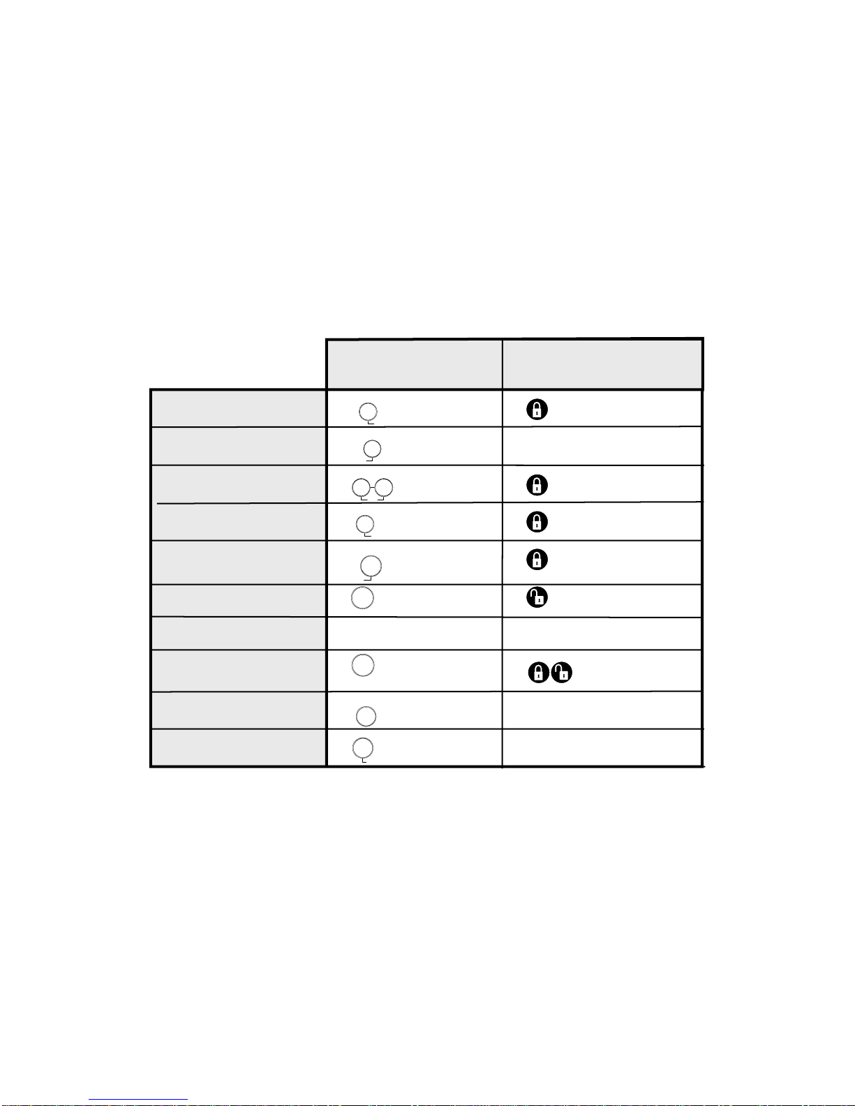
H o w t o . . .
A r m t h e s y s t e m
D o o r s & W i n d o w s
A r m t h e s y s t e m
M o t i o n S e n s o r s
A r m t h e s y s t e m
D o o r s / W i n d o w s & M o t i o n S e n s o r s
A c t i v a t e N o E n t r y D e l a y
A c t i v a t e t h e L a t c h k e y f e a t u r e
D i s a r m t h e s y s t e m
S u d i s a r m t h e s y s t e m
A c t i v a t e a p a n i c a l a r m
C h e c k t h e s y s t e m s t a t u s
S e t d o o r s t o C h i m e
C O N T R O L P A N E L K E Y C H A I N T O U C H P A D
P r e s s T w i c e
P r e s s T w i c e
A c c e s s C o d e
M a s t e r C o d e
P r e s s o n c e
P r e s s & h o l d
f o r 2 s e c o n d s
P r e s s o t h & h o l d
f o r 3 s e c o n d s
P r e s s 3 t i m e s
P r e s s o n c e i f
p r o g r a m m e d
P r e s s t w i c e
Q u i c k R e f e r e n c e T a b e
P r e s s o n c e
P r e s s o n c e
W i n d o w s
D o o r s &
A r m
P r e s s o n c e
S e n s o r s
M o t i o n
A r m
P r e s s o n c e
S e n s o r s
M o t i o n
W i n d o w s
D o o r s &
A r m
P r e s s e a c h
u t t o n o n c e
W i n d o w s
D o o r s &
A r m
S e n s o r s
M o t i o n
A r m
D i s a r m
+
S t a t u s
S y s t e m
D o o r s
C h i m e
P r e s s o n c e
A U X
Table of contents
Other Protect America Security System manuals


