Protect EUROPROT Plus Operating instructions

Troubleshooting of EuroProt+ devices
Arrranged by: Péter Erdős
Zoltán Seida
PR-MU-27-11
Valid from:
2016-01-22
Page: 1 / 28
Approved by: László Eperjesi
Revision: 1
Troubleshooting
Troubleshooting of EuroProt+ devices
Arrranged by: Péter Erdős
Zoltán Seida
PR-MU-27-11
Valid from:
2016-01-22
Page: 2 / 28
Approved by: László Eperjesi
Revision: 1
1Basic information .......................................................................................4
1.1 The human-machine interface (HMI).....................................................4
2Settings of the Ethernet connection...........................................................6
2.1 Connection to the device with fix IP address .........................................6
2.2 Connection to the device with the embedded DHCP server..................7
3Connection to the device ...........................................................................9
3.1 Connection with EOB.............................................................................9
3.2 Connection with RJ45 connector......................................................... 10
4Handling the website of the device .......................................................... 11
5Necessary data before contacting Protecta Support................................ 13
5.1 Serial Number of the Device................................................................ 13
5.2 Information about RDSP, CDSP and configuration versions ............... 15
5.3 IED-EP+ S24 with b/w display............................................................. 16
6Normal Start-up of the Device..................................................................17
7Firmware Update ..................................................................................... 18
8Warning and Error Messages .................................................................. 20
8.1 Warning messages on the web page................................................... 20
8.2 Error messages on the web page........................................................ 23
8.3 Error messages on the LCD screen..................................................... 24
9Quick Troubleshooting............................................................................. 26

Troubleshooting of EuroProt+ devices
Arrranged by: Péter Erdős
Zoltán Seida
PR-MU-27-11
Valid from:
2016-01-22
Page: 3 / 28
Approved by: László Eperjesi
Revision: 1
The scope of this document is to help to identify errors that may occur during the
operation of EuroProt+ devices.
To achieve the goal of the effective and fast troubleshooting it is recommended
to execute the processes described in this document and collect information
before contacting Protecta Support.
If you need the help of the Protecta support staff, then please submit a ticket in
our web-support system:
http://buy.protecta.hu/support/?language=English
For experienced users:
If you well know the basic handling of the devices, then please scroll to chapter 5.
The first four chapters contain basic information about the handling of the
devices.
Troubleshooting of EuroProt+ devices
Arrranged by: Péter Erdős
Zoltán Seida
PR-MU-27-11
Valid from:
2016-01-22
Page: 4 / 28
Approved by: László Eperjesi
Revision: 1
1 Basic information
The EuroProt+ devices indicate immediately any malfunctions due to the
embedded fault detection algorithm. Alerts are given by the Device Status LED
and the Fault relay.
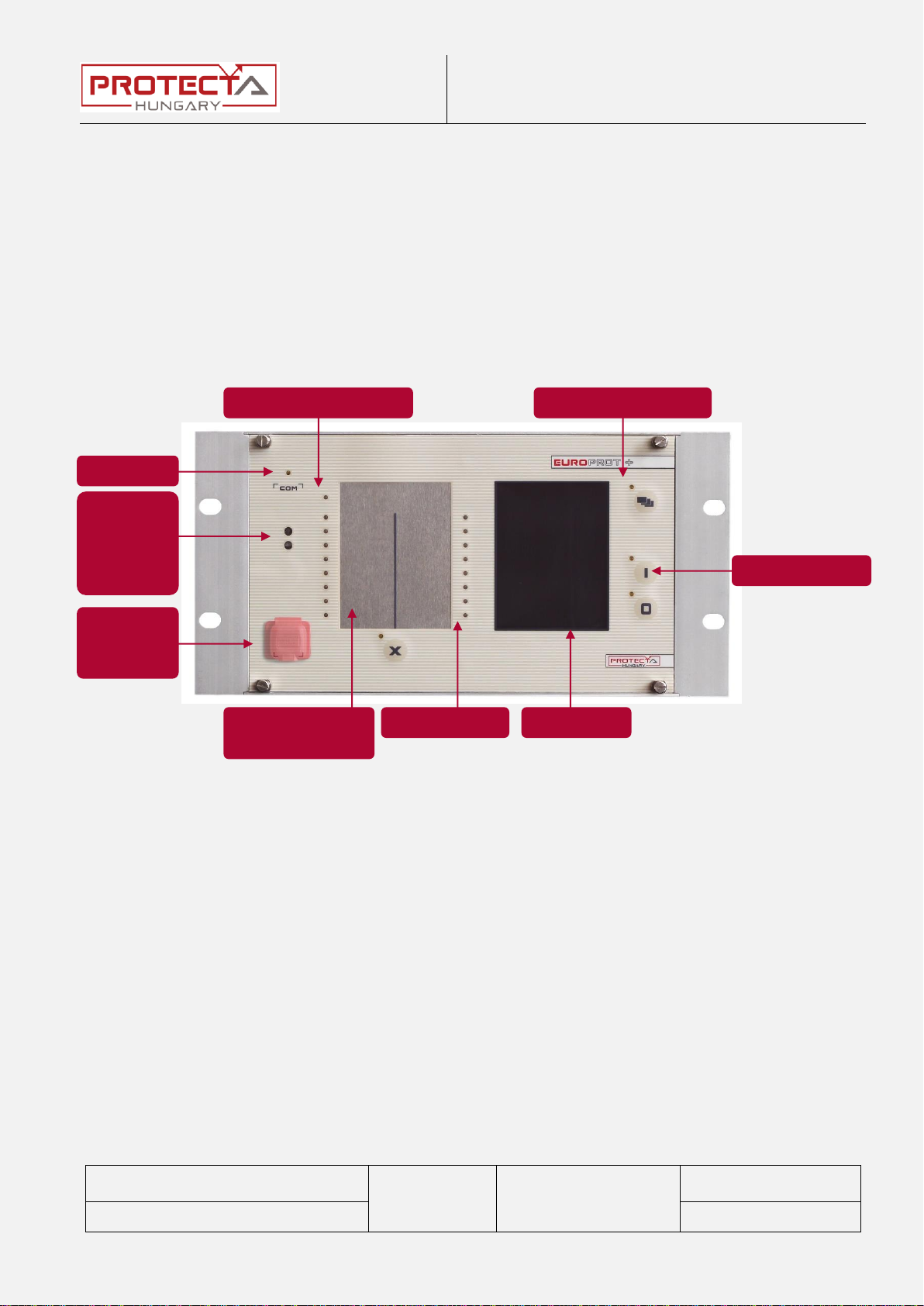
1.1 The human-machine interface (HMI)
The human-machine interface is realized by the front panel of the device, see the
picture below.
Figure 1-1 The front panel of the device
Optical
interface
for factory
usage
COM LED
Device status LED
Touch key LEDs
Touch keys
TFT display
User LED-s.
Changeable LED
description labels.
Ethernet
service
port

Troubleshooting of EuroProt+ devices
Arrranged by: Péter Erdős
Zoltán Seida
PR-MU-27-11
Valid from:
2016-01-22
Page: 5 / 28
Approved by: László Eperjesi
Revision: 1
16 pieces user LEDs
Three-color, 3 mm circular LEDs
COM LED
Yellow, 3 mm circular LED indicating EOB/RJ-45 (on
the front panel) communication link and activity
Capacitive touch key
LEDs
4 pcs yellow, 3 mm circular LEDs indicating touch key
actions
Device status LED
1 piece three-color, 3 mm circular LED
Green: normal device operation
Yellow: warning signal
Red: error signal
Device keys
(I, O, X, Page)
Capacitive touch keys
Tactile push buttons (on the 24 HP devices)
Buzzer
Audible touch key pressure feedback
Changeable LED
description label
Describes user LED functionality
Display
320 × 240 pixel TFT colour display with resistive
touchscreen interface (3.5” or optional 5.7”)
128 × 64 LCD black & white display
Optical interface for
factory usage
For debugging and software development purposes
Only for 42 and 84 HP devices.
EOB connector
Ethernet Over Board: communication interface
accomplishes isolated, non-galvanic Ethernet
connection with the help of a magnetically attached
EOB device. The EOB device has an RJ-45 type
connector supporting 10Base-T Ethernet connection
to the user computer. This is a proprietary and
patented solution from Protecta Ltd.
EOB2 device supports 10/100Base-Tx interface.
Ethernet service port
IP56 rated Ethernet 10/100-Base-T interface with RJ-
45 type connector (IP56 only valid if the cap of the
service port is closed.)
Table 1-1 Data of the HMI
Troubleshooting of EuroProt+ devices
Arrranged by: Péter Erdős
Zoltán Seida
PR-MU-27-11
Valid from:
2016-01-22
Page: 6 / 28
Approved by: László Eperjesi
Revision: 1
2 Settings of the Ethernet connection
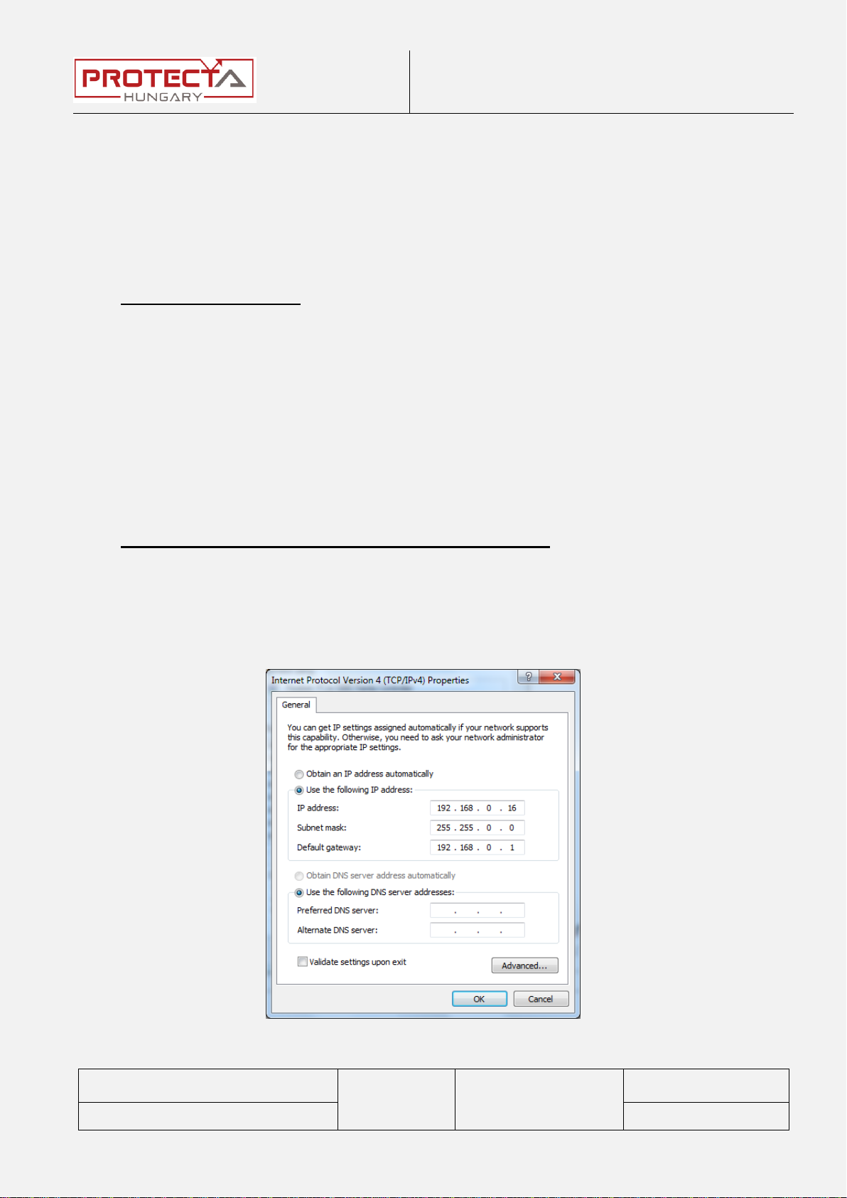
2.1 Connection to the device with fix IP address
The address can be freely changed by the user. If the user’s computer has fix
IP address, then this and the netmask have to be set according to the used IP
address range and netmask.
Setting of the device:
The IP settings of the device get the following default values at the first start:
IP address: 192.168.0.15
Netmask: 255.255.0.0
Default gateway:192.168.1.1
IP address mode: Static IP
DNS1 and DNS2 address: 0.0.0.0
DHCP server: Disabled
These can be changed in System settingsStation bus menu settings menu.
Setting of the user's computer (with fix IP address)
The possible IP settings of the user’s computer according to the (optional)
device settings above:
IP address: in range from 192.168.0.1 to 192.168.254.254
Netmask: 255.255.0.0
Default gateway:192.168.0.1
Figure 2-1 The possible settings of the user’s computer (with fix IP address)

Troubleshooting of EuroProt+ devices
Arrranged by: Péter Erdős
Zoltán Seida
PR-MU-27-11
Valid from:
2016-01-22
Page: 7 / 28
Approved by: László Eperjesi
Revision: 1
2.2 Connection to the device with the embedded DHCP
server
The embedded DHCP server can be enabled in System settingsStation bus
settings menu.
If this type of connection needs to be used only through the front panel connector,
then the “Front only” value has to be chosen for this parameter.
Figure 2-2 Setting the DHCP server in the device
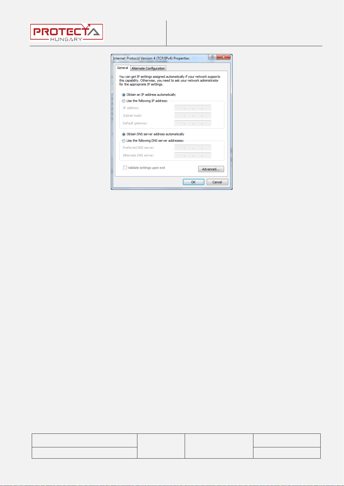
If the DHCP server of the device is used, then the settings of the user’s computer
is recommended to apply according to Figure 2-3.
Troubleshooting of EuroProt+ devices
Arrranged by: Péter Erdős
Zoltán Seida
PR-MU-27-11
Valid from:
2016-01-22
Page: 8 / 28
Approved by: László Eperjesi
Revision: 1
Figure 2-3 The possible settings of the user’s computer (with dynamic IP
address)

Troubleshooting of EuroProt+ devices
Arrranged by: Péter Erdős
Zoltán Seida
PR-MU-27-11
Valid from:
2016-01-22
Page: 9 / 28
Approved by: László Eperjesi
Revision: 1
3 Connection to the device
3.1 Connection with EOB
The type of the frontpanel communication connector can be either RJ-45 or EOB,
according to the customer’s requirement. In the second case the user needs EOB
(10 Base-Tx interface) or EOB2 (10/100 Base-Tx interface) adapter (EOB2 for
newer devices), with which the embedded web-server and for the EuroCAP the
device is available. The join of the EOB connector to the device is solved by
magnets.
Necessary tools:
Computer
UTP cable
EOB or EOB2 adapter (EOB2 can be used only by the attached special
cable!)
Figure 3-1 Connection with EOB and EOB2 adapter
Troubleshooting of EuroProt+ devices
Arrranged by: Péter Erdős
Zoltán Seida
PR-MU-27-11
Valid from:
2016-01-22
Page: 10 / 28
Approved by: László Eperjesi
Revision: 1
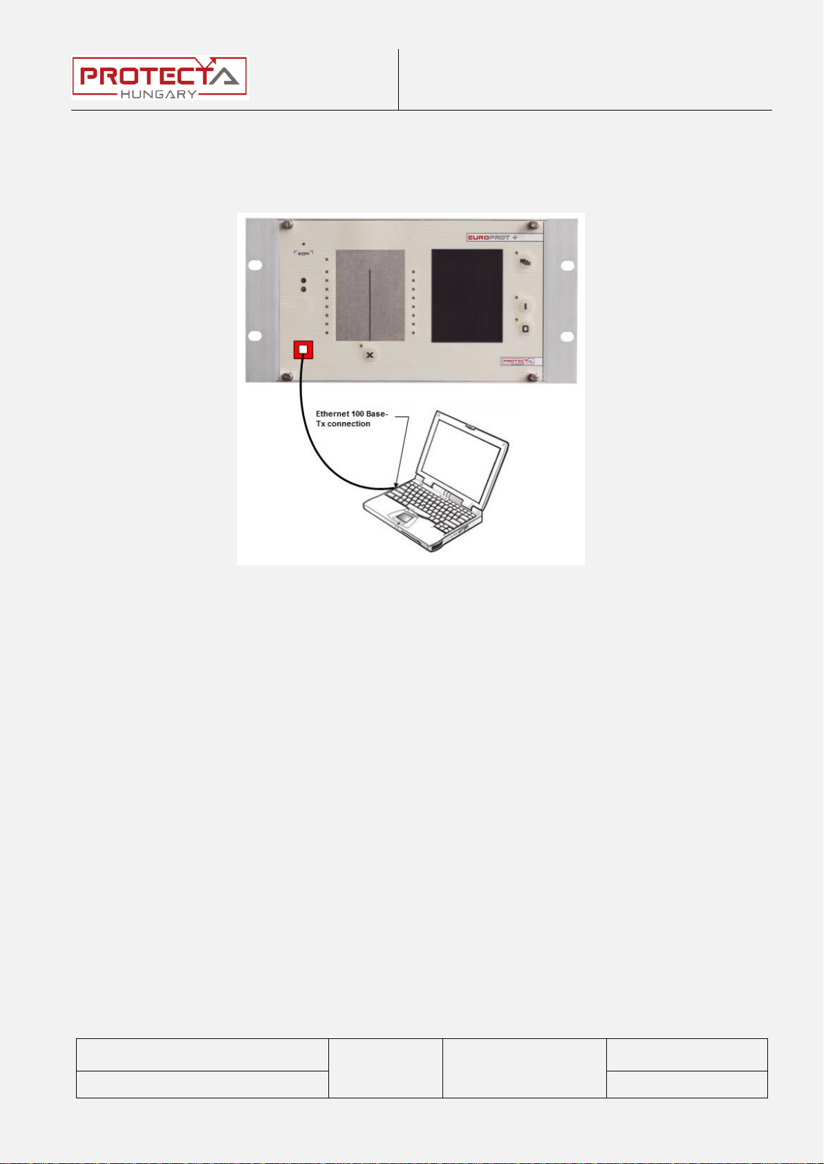
3.2 Connection with RJ45 connector
If you use the RJ-45 connector on the front panel, then you need only a UTP-
cable and a computer. With older computer you might need cross type UTP cable.
Figure 3-2 Connection with RJ-45 connector
Troubleshooting of EuroProt+ devices
Arrranged by: Péter Erdős
Zoltán Seida
PR-MU-27-11
Valid from:
2016-01-22
Page: 11 / 28
Approved by: László Eperjesi
Revision: 1
4 Handling the website of the device
The website of the device can be accessed by a compatible web browser
through Ethernet connection.
In order to display the website correctly, the browser needs to be HTML5
compatible. This requirement is met by the up-to-date web browsers (e.g.
Internet Explorer 9 or higher).
After the physical connection to the device has been set up, its website is
available by the IP address of the device.
More details can be found in the description "Remote user interface
description".
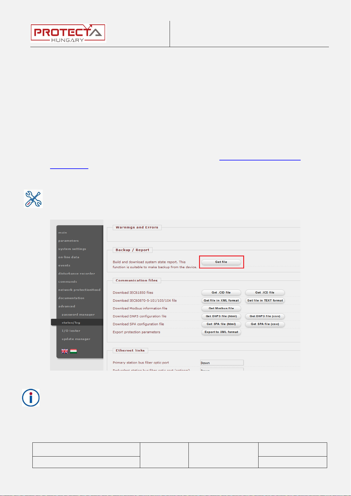
The work of the support and service team will be facilitated, if in case of some
error we get detalied information. The most information about the state of the
device are stored in the report file which can be downloaded from the website
of the device in the menu advanced
status/log, in the Backup / Report
window.
Figure 4-1 Downloading the report file
Some functions of the device can be protected by password. This protection can
be applied either for the local use (TFT-display), or for remote use (website,
SCADA), or for both.
- Master password: it locks the access to the advance menu (where e.g. the
passwords can be managed).
Troubleshooting of EuroProt+ devices
Arrranged by: Péter Erdős
Zoltán Seida
PR-MU-27-11
Valid from:
2016-01-22
Page: 12 / 28
Approved by: László Eperjesi
Revision: 1
- Password for Settings: it locks the settings of the function parameters.
- Password for Control: it locks the control commands (e.g. circuit breaker
control, resetting of latched signals).
In the devices delivered from the Protecta factory there are not set any
passwords! If there is a password set in a device, it is set by the end-user.

Troubleshooting of EuroProt+ devices
Arrranged by: Péter Erdős
Zoltán Seida
PR-MU-27-11
Valid from:
2016-01-22
Page: 13 / 28
Approved by: László Eperjesi
Revision: 1
5 Necessary data before contacting Protecta Support
The data below have to be provided when contacting us, so the device can be
identified quickly:
Serial No. of the device
RDSP version
CDSP version
Configuration name and date
5.1 Serial Number of the Device
There are several ways to read the serial number.
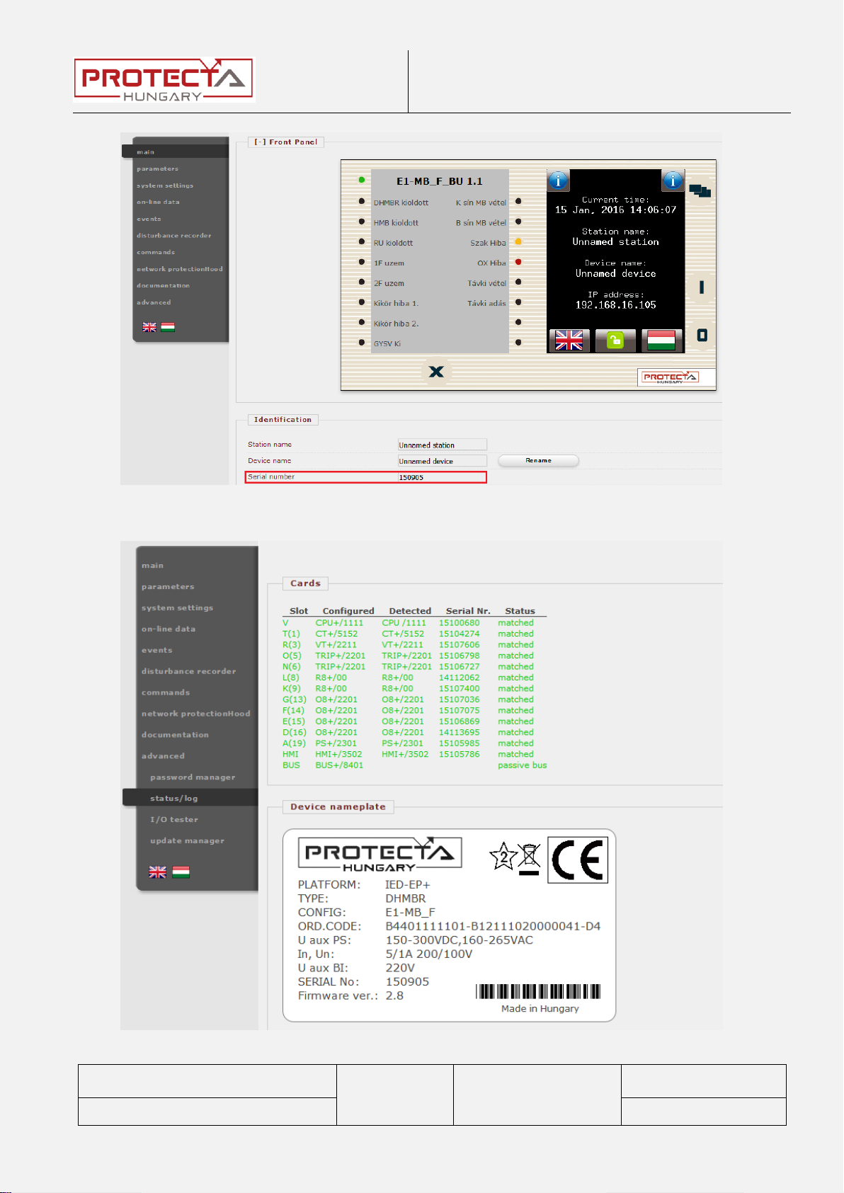
First it can be found on the Device Nameplate which is located on the upper half
of the right of the device, close to the backplane.
Figure 5-1 The Device Nameplate
There are cases when the physical Nameplate cannot be accessed because of
the location of the device. In these cases connect to the IED on its Service Port,
and open its web page. Here the serial number can be found in two places: in the
main menu (Identification section) or in the advanced status/log menu where
the Virtual Nameplate (equivalent of the physical one) can be found.
Troubleshooting of EuroProt+ devices
Arrranged by: Péter Erdős
Zoltán Seida
PR-MU-27-11
Valid from:
2016-01-22
Page: 14 / 28
Approved by: László Eperjesi
Revision: 1
Figure 5-2: Main menu on the webpage
Figure 5-3: A The Virtual Nameplate

Troubleshooting of EuroProt+ devices
Arrranged by: Péter Erdős
Zoltán Seida
PR-MU-27-11
Valid from:
2016-01-22
Page: 15 / 28
Approved by: László Eperjesi
Revision: 1
5.2 Information about RDSP, CDSP and configuration
versions
The firmware versions can be shown on the device touch screen by touching
either of the icons.
Figure 5-4 Firmware and configuration information
If the local screen cannot be accessed, the web page can also be used to obtain
the version information in the advanced update manager menu. (Figure 5-5).

Troubleshooting of EuroProt+ devices
Arrranged by: Péter Erdős
Zoltán Seida
PR-MU-27-11
Valid from:
2016-01-22
Page: 16 / 28
Approved by: László Eperjesi
Revision: 1
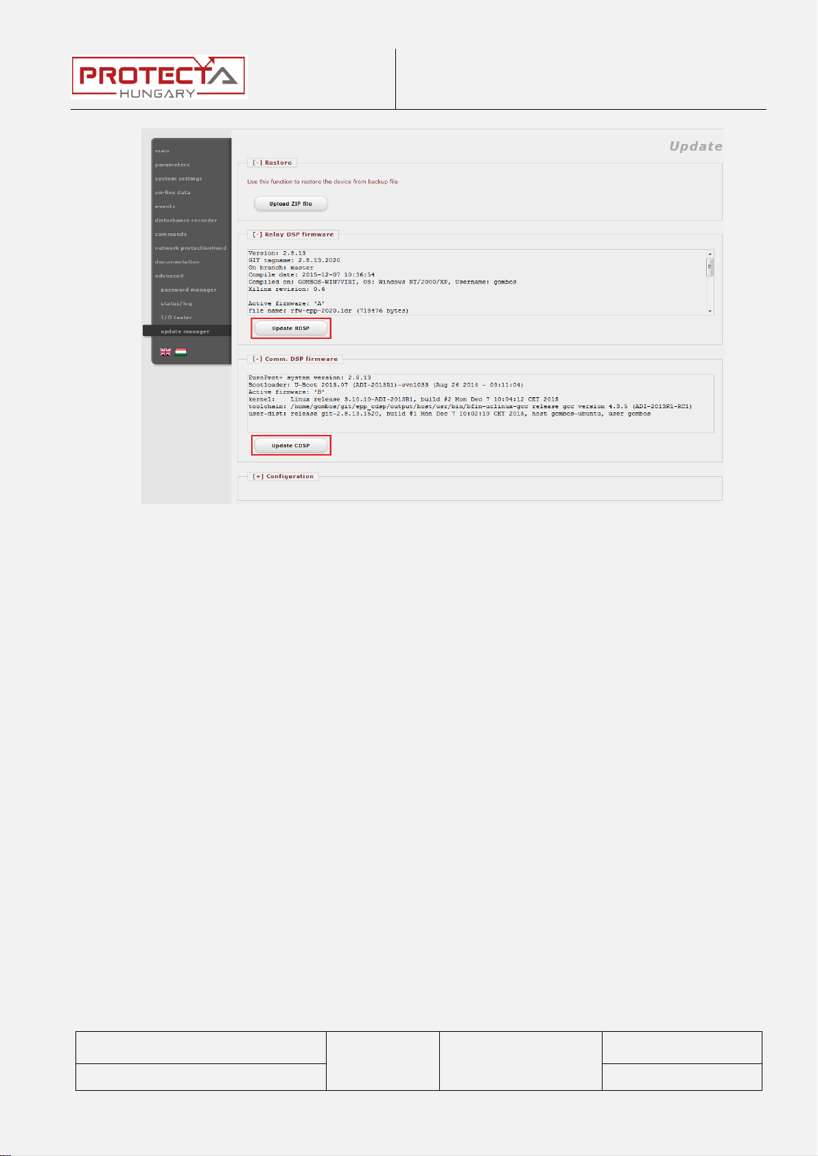
Figure 5-5 update manager on the web page
5.3 IED-EP+ S24 with b/w display
S24 devices with b/w display have different main screen than the others (Info
menu). Here all necessary information keeps rolling on the screen, so they can
be read easily. On the remote side, the web page stays the same, so it can be
used just like the before.

Troubleshooting of EuroProt+ devices
Arrranged by: Péter Erdős
Zoltán Seida
PR-MU-27-11
Valid from:
2016-01-22
Page: 17 / 28
Approved by: László Eperjesi
Revision: 1
Figure 5-6 Front panel of the S24 device
6 Normal Start-up of the Device
1. Connect to supply.
2. The status LED is yellow, then turns red, and finally green. The COM LED
flashes once. These all take about 6 seconds together.
3. Once the status LED turns green, the protection functions are active, the
Failure Relay contact drops off. The remaining process is the start-up of
the communication software.
4. The LCD shows a clock symbol pulsating in the middle of the screen. This
takes about 20 seconds.
5. The logo of Protecta Ltd. appears on the LCD, then finally the main screen
of the configuration is shown.

Troubleshooting of EuroProt+ devices
Arrranged by: Péter Erdős
Zoltán Seida
PR-MU-27-11
Valid from:
2016-01-22
Page: 18 / 28
Approved by: László Eperjesi
Revision: 1
7 Firmware Update
New developments, user requests cause thefirmwares of the devices to get more
and more updates. From time to time there may be updates that are important to
install on previously released devices.
Firmware update can only be done after contacting the Protecta staff!
All digital outputs (relay contacts, trip contacts) must be disconnected from
the protected object(s) before commencing firmware update.
Firmware update must always be done with care, because mistakes in this
process may cause devices malfunction!
It is advised to get the system state report of the device (report.zip) before
commencing the update. This way the device will be able to be restored if
something goes wrong.
The update goes as follows:
1. After connecting to the device, download the report.zip file (advanced
status/log Backup / Report)
Note: If the downloaded file has a size of less than 500 kB, then the download
was not successful, try it again.
2. Delete all disturbance records in the disturbance recorder menu using the
Erase all records button.
3. Restart the device.
4. Go to the advanced update manager menu. Here the RDSP and the
CDSP firmware can be updated with the Update RDSP and Update CDSP
buttons.
Troubleshooting of EuroProt+ devices
Arrranged by: Péter Erdős
Zoltán Seida
PR-MU-27-11
Valid from:
2016-01-22
Page: 19 / 28
Approved by: László Eperjesi
Revision: 1
Figure 7-1 The update manager

Troubleshooting of EuroProt+ devices
Arrranged by: Péter Erdős
Zoltán Seida
PR-MU-27-11
Valid from:
2016-01-22
Page: 20 / 28
Approved by: László Eperjesi
Revision: 1
8 Warning and Error Messages
Inappropriate or faulty conditions cause the device to give warning or error
messages which can be seen in the advanced status/log menu below the
Warnings and Errors point. In some cases the warning/error message can also
be seen on the local display of the device.
8.1 Warning messages on the web page
In case of warnings the status LED turns usually yellow (exceptions are shown in
the table below), and a yellow triangle appears on the web page below the menu
list with an exclamation mark in it.
In this case several functions are unable to work depending on the fault. The
possible messages are listed in the table below.
Figure 8-1 Warning message on the web page
Warning message (RDSP)
Explanation
0x0100 Card detection
More modules are detected than configured in
the configuration
0x0010 PS unstable
Power supplies with auxiliary voltage monitor
(PS+xxx2) detect unstable voltage
Warning message (CDSP)
Explanation
0x0020 Time sync
This warning appears if the “Timesync
warning” parameter is set in the system
parameters Time synchronization menu
and no synchronization signal is detected.
Table of contents


