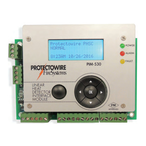
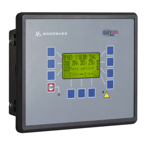
Protectowire CTM-530 Series Operating instructions

FireSystems
PROTECTOWIRE
®
RX
TX
PC--1239
JP2
K1
K2
K3
CTM-530
LINEAR
HEAT
DETECTOR
POWER
ALARM
FAULT
SHORT
APPROVED
FM
OKESC
JP2
PROTECTOWIRE CTI-155
NORMAL
12:45 PM 4/16/2020
RX
TX
PC--1239
JP2
K1
K2
K3
CTM-530
LINEAR
HEAT
DETECTOR
POWER
ALARM
FAULT
SHORT
APPROVED
FM
OKESC
JP2
PROTECTOWIRE CTI-155
NORMAL
12:45 PM 4/16/2020
CTM-530 Series Interface Module
with Modbus Over RS-485
Installation and Operation Guide
An ISO 9001 Registered Company

FireSystems
PROTECTOWIRE
®
MAN-2006 Last modified 3/26/2021
Contains updates included in Firmware v1.3.5
© 2020 The Protectowire Co., Inc.
60 Washington Street
Pembroke, MA 02359
Phone 781-826-3878 • Fax 781-826-2045
E-Mail: pwir[email protected]
WWW.PROTECTOWIRE.COM
CTM-530 Series Interface Module
Installation and Operation Guide

How CTI Technology Works
Digital Linear Heat Detection Operation ......................................................................................... 1
CTI Linear Heat Detection Operation ............................................................................................. 2
The CTM-530 Interface Module
General Information......................................................................................................................... 4
Description....................................................................................................................................... 4
Specifications.................................................................................................................................... 5
4-20mA Output Information ........................................................................................................... 6
Installation and Wiring..................................................................................................................... 7
Mounting and Location ....................................................................................................... 7
Wiring Diagram................................................................................................................... 7
Detector Wiring................................................................................................................... 8
Interface Wiring................................................................................................................... 8
Power Wiring....................................................................................................................... 9
4-20mA Outputs wiring ...................................................................................................... 9
Configuration & Feature Selection ................................................................................................. 10
Configuration Prerequisites................................................................................................ 10
Initial Power Up................................................................................................................. 10
Display, Menus and Navigation Controls........................................................................... 10
Accessing the Menu ........................................................................................................... 10
Resetting the Detector ....................................................................................................... 11
Detector Type Selection ..................................................................................................... 12
Display Units..................................................................................................................... 13
Alarm Point Location (APL) Setup .................................................................................... 13
Junction Test Bypass...........................................................................................................17
Time and Date Setup......................................................................................................... 18
Password Setup .................................................................................................................. 18
Factory Restore .................................................................................................................. 18
Event History..................................................................................................................... 19
Cold Junction Test and Offset............................................................................................ 20
4-20mA Output Calibration.............................................................................................. 21
Operation and Testing .................................................................................................................... 22
Testing Notes..................................................................................................................... 22
Inspection of the Installation.............................................................................................. 22
Confirming Detector Connection Polarity......................................................................... 22
Detection Operation and Testing ....................................................................................... 23
1. Test Open Circuit Monitoring ...................................................................................... 23
2. Test Short Fault Monitoring.......................................................................................... 24
3. Testing Alarm Activation with CTI............................................................................... 26
4. Verify Temperature Measurements ................................................................................ 28
Testing Accessories..................................................................................................................... 29,30
Hazardous Location Applications (Factory Mutual Only)............................................................... 31
Intrinsic Safety Barrier, Option I........................................................................................ 31
ISB Illustration Drawing IL-1622...................................................................................... 32
Table of Contents

Modbus Over RS-485 Operation Guide
Descriptions ................................................................................................................................... 33
RS-485 Serial Bus .............................................................................................................. 33
Modbus Protocol ...............................................................................................................33
CTM-530 Modbus over RS-485........................................................................................ 33
Specifications.................................................................................................................................. 34
Port Specifications.............................................................................................................. 34
Protocol Specifications ....................................................................................................... 34
Wiring
Wiring Description............................................................................................................35
Wiring Diagram................................................................................................................. 35
Example Bus Diagram ....................................................................................................... 35
Configuration Settings
Configuration Settings Descriptions................................................................................... 36
Accessing the Modus Menu ............................................................................................... 36
Setting the Slave Address.................................................................................................... 37
Setting the Parity ............................................................................................................... 37
Setting the Baud Rate ........................................................................................................ 38
Modbus Communications
Modbus Protocol Info........................................................................................................ 38
Register Overview.............................................................................................................. 38
Module Status.................................................................................................................... 39
Temperature Readings........................................................................................................ 40
Event Distance Measurements............................................................................................ 40
Cold Junction Temperature................................................................................................ 40
Detector Type .................................................................................................................... 41
Initialize / Reset ................................................................................................................. 41
Table of Contents

Page 1
CTI stands for Confirmed Temperature Initiation and is a new Digital Linear Heat Detection technology
created and patented by The Protectowire Company. This technology is an enhancement to traditional digital
linear heat detection technology and provides for short circuit discrimination.
CTI confirms thermal activation of the Digital Linear Heat Detector before an alarm is initiated thereby re-
ducing the incidence of false alarms created by physical damage to the detector.
Protectowire CTI Digital Linear Heat Detectors are the only digital linear heat detectors to provide Short
Circuit Discrimination.
Introduction to CTI™ Technology
How CTI™ Technology Works
Digital Linear Heat Detection Operation
To understand how CTI technology works it is important to have an understanding of how traditional digital
linear heat detectors operate.
Figure 1 - Traditional digital linear heat detectors are constructed of a twisted pair of spring conductors coated
with a thermoplastic coating designed to soften at a specific temperature. An initiating device circuit monitors
a length of this detector installed in an area to be protected.
Monitor
Circuit
End Line
Resistor
Heat Sensitive
Insulation
Normal
G
Figure -1
Figure 2 - Traditional digital linear heat detectors are constructed of a twisted pair of spring conductors coated
with a thermoplastic coating designed to soften at a specific temperature. An initiating device circuit monitors
a length of this detector installed in an area to be protected.
HEAT
Monitor
Circuit
End Line
Resistor
Heat Sensitive
Insulation
Alarm!
R
Figure - 2

Page 2
CTI technology is an enhancement to standard digital linear heat detection operation. Where traditional dig-
ital linear heat detectors have a single mode of detection, CTI digital linear heat detectors add a second mode
of detection. This second mode of detection utilizes the thermo-electric effect to measure the temperature at
the short circuited point of the detector to confirm a true alarm condition exists.
Figure 3 - The Thermo-electric Effect is the production of an electromotive force (Voltage) in a loop of
conductors consisting of two dissimilar materials. When two junctions in the conductors are maintained at
different temperatures a voltage is produced relative to the temperature difference between the two junctions.
This voltage is used to measure temperature in devices called Thermocouples.
CTI™ Digital Linear Heat Detector Operation
Figure -3
Figure 4a - CTI digital linear heat detectors are constructed of a twisted pair of dissimilar metal spring con-
ductors coated with a thermoplastic coating designed to soften at a specific temperature. An initiating device
circuit monitors a length of this detector installed in the area to be protected.
Conductor A
Measurment
Junction
Conductor B
Voltmeter
+
-
Reference
Junction
Measurment
Device
Thermocouple
HEAT
This very reliable method of detection has been in use for over 75 years in the fire protection industry; however
the possibility of mechanical damage causing a short circuit does exist. A short caused by mechanical damage
will produce a false alarm condition therefore care needs to be taken during installation and design to locate
the detector in areas it is least likely to be subjected to physical damage.
Monitor
Circuit
End Line
Resistor
Heat Sensitive
Insulation
Normal
G
Figure -4a

Page 3
Figure 4b - When a short occurs at a point along the detectors length an initiating device circuit detects the
short and then automatically switches to a thermocouple measurement mode. The shorted portion of the de-
tector forms a thermocouple junction which can be measured. The thermocouple measurement represents the
current temperature of the shorted portion of detector. If the short is below the pre-set alarm threshold for the
detector, in this example 280°F (138°C), a short fault is reported instead of an alarm condition.
Figure -4b
Figure 5 - If the short temperature is measured to be above the pre-set 280°F (138°C) alarm threshold, as in
this example, an alarm condition is produced immediately.
COLD
TEMP
Monitor
Circuit
End Line
Resistor
Heat Sensitive
Insulation
Short
Y
82f-27C
HEAT
TEMP
Monitor
Circuit
End Line
Resistor
Heat Sensitive
Insulation
Alarm
R
282f-139C
Figure -5

The CTM-530 Series
Interface Module
General Information
The Protectowire CTM-530 is a detection control module that is an interface between a main fire alarm
control panel detection circuit or addressable node and Protectowire Type CTI Linear Heat Detector. The
module provides one (1) supervised detection circuit that may be field wired for either Class A (Style D) or
Class B (Style B) service. The alarm initiating circuit is capable of operating a maximum of 4000 feet (1220
meters) combined total of Protectowire Type CTI Linear Heat Detectors and appropriate thermocouple
grade extension cable. Protectowire offers thermocouple grade extension cable as part numbers PWTX-200
and PWTX-500. The PWTX cable offered is for non-classified hazards only. The CTM-530 initiating circuit
is designed to monitor Protectowire Type CTI Linear Heat Detector only and does not support other types
of normally open contact alarm initiating devices.
Description
The CTM-530 operates using the Protectowire patented CTI Confirmed Temperature Initiation technology.
When paired with Protectowire Type CTI Linear Heat Detectors, the module can distinguish between a me-
chanical short in the linear heat detector and thermal alarm activation, which greatly reduces the risk of false
alarms resulting from physical damage to the detector. This multi-criteria detection method provides for
short circuit discrimination, a feature previously unavailable for conventional digital type linear heat
detectors.
The CTM-530 is designed for easy installation and is available in an optional NEMA-4X rated enclosure for
mounting outside of the host fire alarm control panel or remotely near the hazard to be protected. In order
to ensure proper operation, each CTM-530 module requires regulated resettable external power which is
normal-ly provided by the host fire alarm panel. Each module contains a green “Power-On” LED indicator,
one (1) red “Alarm” LED indicator, one (1) yellow “Fault” LED indicator and one (1) yellow “Short”
indicator. On (1) set of Form C alarm contacts, one (1) set of Form C general fault contacts and one(1) set of
Form C short circuit fault contacts are provided to connect the unit to the host fire alarm panel. The module
also provides tow 4-20mA outputs one which allows monitoring of the module status and the other for alarm
point location information.
In addition to the features listed above the standard version of the module, model CTM-530, provides a 4x20
LED back-lit LCD display and navigation buttons for access to a complete menu driven user interface. Also
available is model CTM-530LT which is intended for use in low temperature applications. The LT version of
the interface module contains no LCD display or navigation buttons and no menu accessible user interface
and therefor requires the use of the optional CTMP-1 Programmer for system commissioning, setting alarm
temperatures and accessing history data.
Page 4
RX
TX
PC--1239
JP2
K1
K2
K3
CTM-530
LINEAR
HEAT
DETECTOR
POWER
ALARM
FAULT
SHORT
APPROVED
FM
OKESC
JP2
PROTECTOWIRE CTI-155
NORMAL
12:45 PM 4/16/2020
RX
TX
PC--1239
JP2
K1
K2
K3
CTM-530
LINEAR
HEAT
DETECTOR
POWER
ALARM
FAULT
SHORT
APPROVED
FM
OKESC
JP2
PROTECTOWIRE CTI-155
NORMAL
12:45 PM 4/16/2020

Page 5
Specifications
Electrical
• Power input - Regulated 12 to 24 VDC (+10% / -15%) @ 1.6 Watts
• Power Limited, onboard surge and EMI protection device
Inputs
• One initiating device circuit capable of monitoring up to 4000 Feet (1220 Meters) of Protectowire Type
CTI Linear Heat Detector. For all CTI type detectors, twisted “T” type extension grade thermocouple
wire is required for use as interconnecting wire on the detection circuit. Minimum conductor size is
20AWG (0.812mm), or as require by local code.
• For intrinsically safe applications (Option I), the maximum detector length per zone is 2,000 feet
(600m) or less, as determined by the hazardous location calculation and application.
Environmental
• Ambient temperature range:
Standard version (With integrated LCD display) -20° to 120°F (-29° to 49°C)
LT version (Without integrated LCD display) -40° to 120°F (-40° to 49°C)
Standard & LT versions FM tested to 140°F (60°C) max
• Humidity: Max. 95% non-condensing
Visual Annunciation
• 4x20 Character LED back-lit LCD display
• One green “Power” indicator
• One red “Alarm” indicator
• One yellow “Fault” indicator
• One yellow “Short” indicator
Status Relay Contacts (Rated 1 ampp @24VDC Resistive Load)
• One (1) set of Form C (SPDT) Fault Contacts
• One (1) set of Form C (SPDT) Short Fault Contacts
• One (1) set of Form C (SPDT) Alarm Contacts
• One yellow “Short” indicator
4-20mA Outputs
• One (1) 4-20mA Output for module status
• One (1) 4-20mA Output for Alarm Point Location Readings
Board Assembly Dimensions
• 6” W x 4” H x 1.5” D (15.24cm x 10.16cm x 3.8cm)
• Mounting holes #4 holes at 5.5” (13.97cm) x 3.5” (8.89cm) spacing
Enclosure Option
• 8” H x 6” W” x 4” D (27.24cm x 15.24cm x 10.16cm)
• Add 1.6” (4cm) to overall height for external mounting feet
• Clear full view door
• *NEMA 4X Rated (Rating UL listed only)
(Closest IEC equivalent - IP66)
Note: Option I (ISB) increases enclosure size
* Additional enclosures and sizes available. Consult factory.

Page 6
4-20mA Output Information
Description - The CTM-530 provides wo 4-20mA outputs that allow for monitoring of the module status
and active alarm point location reading. These outputs are intended for annunciation purposes only. Module
monitoring is intended to be accomplished using the on board supplied dry contacts connected to a listed or
approved fire detection control panel initiation deice circuit.
For Class “A” wiring configuration the status output will also indicate which detector input is currently being
measured by the alarm point location meter. The measurement is alternated between inputs approximately
every 3 seconds with the status output indication which input is currently being read.
The output levels are detailed below.
Status Output - 4-20mA Output Loop 1:
Loop Fault - 4mA or less
Open - 6mA
Normal - 10mA
Initiating Device Circuit Out Short Fault - 13mA
Initiating Device Circuit Return Short Fault - 15mA
Initiating Device Circuit Out Alarm - 17mA
Initiating Device Circuit Return Alarm - 19mA
Note: For systems employing an isolated power source for the 4-20mA loops; Module Power Failure will
report at greater than or equal to 20mA.
Alarm Point Location Output - 4-20mA Output Loop 2:
4-20mA Full Scale corresponds to 0-8000 Feet
4mA = 0 Feet -20mA = 8000 Feet.
To calculate current to distance in feet use the following formula:
Current in mA = (I)
(I-4) / 0.002 = Distance in Feet
To convert to Meters:
Distance in Feet x 0.3048
Note: To insure status levels the total 4-20mA measurement loop resistance including feed cable, measurement device
and load resistor must not exceed the values below.
Supply Voltage @ 12VDC - Total loop resistance not to exceed 300 Ohms
Supply Voltage @ 24VDC - Total loop resistance not to exceed 800 Ohms

Page 7
Installation and Wiring
Mounting and location - The CTM-530 can be provided as a complete module assembly for installation in
a customer supplied enclosure or pre-mounted in a factory supplied enclosure. Please refer to the specification
section for enclosure information. When mounting the CTM-530 please follow the installation guidelines
below.
The CTM-530 interface module shall be located in a clean, dry, vibration free environment and shall not be
subjected to temperatures or humidity that exceeds the modules specifications.
The CTM-530 should be mounted in an accessible location where the user interface can be viewed without
obstruction.
The enclosure rating should meet or exceed that which is required for the installation environment. All en-
closure penetrations should be via connectors and/or conduit hardware that meet or exceed the rating of the
enclosure.
To utilize the maximum detector length capacity of the CTM-530, feed cable lengths should be kept to a
minimum by locating the CTM-530 as close to the area of detection as possible.
Wiring Diagram
OK
NC NO C NO NC C NO NC CRTN OUT +V RTN OUT +V
LOOP 2 LOOP 1 FAULT ALARM SHORT
GND +V COM
+- +-
OUT RET
ESC
POWER
ALARM
FAULT
IDC
FROM HOST
PANEL
(+) (-)
HOST
ZB-5 ZONE
BOX
* TX EXTENSION
ZB-5 ZONE
BOX
PROTECTOWIRE CTI LINEAR
HEAT DETECTOR
(CLASS B)
END LINE
RESISTOR
10K 1
2WATT
(+)
(-)
(+)
(-)
(+)
(-) Note: For CTI type detector and
corrosponding extension cable, polarity
MUST be observed. Copper (CU) colored
conductor is positive, silver (CO) conductor
is negative.
+- +-
OUT RET
* TX EXTENSION CABLES
PROTECTOWIRE CTI LINEAR
HEAT DETECTOR
(CLASS A) (+)
(-)
(+)
(-)
Note: For CTI type detector and
corrosponding extension cable, polarity
MUST be observed. Copper (CU) colored
conductor is positive, silver (CO) conductor
is negative.
(+)
(-)
(+)
(-)
J10
J11
J11
(+)
(-)
POWER
12-24VDC
1.6 WATT
EARTH GND
Note: Connections shown are typical. Other
monitoring scenarios can be congured as
required by the authority having jurisdiction.
NC NO C NO NC C NO NC C
FAULT ALARM SHORT
FROM HOST
PANEL
(+) (-)
HOST ELD
(+) (-)
IDC #1
ALARM
IDC #2
PRE-ALARM
OR SUPVERVISORY
LCD DISPLAY
STATUS
INDICATORS
NAVIGATION
SWITCHES
(+)(-)
A
RES
SUPPLY (-)
SUPPLY (+)
WIRING TYPICAL
FOR LOOP 1 & 2
SUPPLY OF 5-24VDC
MAY BE
LOCAL OR REMOTE
SEE LOOP 1
FOR WIRING
4-20ma
ALARM POINT OUTPUT
4-20ma
STATUS OUTPUT
SUPPLY @ 12V - 300 Ohms
SUPPLY @ 24V - 800 Ohms
TOTAL MEASURMENT LOOP RESISTANCE
INCLUDING FEED CABLE AND LOAD
RESISTOR NOT TO EXCEED BELOW VALUES
Note: If dedicated earth ground is not
available, GND terminal and COM terminal
must be connected to each other.
J9 J13 J12
CONNECTION
DIAGRAM #2
CONNECTION
DIAGRAM #1
Interface Contact wiring 12 AWG to 30 AWG. When
using maximum of two conductors within a single
terminal; 18 AWG Maximum. Wires must be
individually inserted to terminal and not twisted
together as that could aect circuit supervision.
* For all CTI type detectors, twisted "T" type extension grade
thermocouple wire is required for use as interconnecting
wire on the detection circuit. Minimum conductor size is
20AWG (0.812mm), or as required by local code.
CABLE
ELD
CTM-530
**
** Fault contacts shown normally energized.
**
SHORT
DRTB2
Terminal
DRTB2
Terminal
ZB-5 ZONE
BOX
DRTB2
Terminal
ZB-5 ZONE
BOX
DRTB2
Terminal
TX+ TX-
AB
RX+ RX- 1 2
RTERM
RS-485
MODBUS RTU
CU
CO
CU
CO
CU
CO
CU
CO
CU
CO
CU
CO
CU
CO
PROTECTOWIRE CTI-155
NORMAL
11:38am 12/21/2016
FireSystems
PROTECTOWIRE
®
Note: See last page of manual for full size view of this wiring diagram
Figure - 6

Page 8
Installation and Wiring - (continued)
Wire the system according to this manual using Figure 6 as reference. Wiring should be in accordance with
applicable National and/or Local Electrical Fire Alarm Codes.
Detector Wiring - The CTM-530 provides one (1) supervised detection circuit that may be field wired for
either Class A (Style D) or Class B (Style B)service. The alarm initiating circuit is capable of operating up to
4000 feet (1220 meters) of Protectowire Type CTI Linear Heat Detector. The CTM-530 initiation circuit is
designed to monitor Protectowire Type CTI Linear Heat Detector only and does not support other types of
normally open contact alarm initiating devices.
Step 1 - Remove the factory supplied 10K 1/2w end-of-line resistor (ELR) from terminal J11 TC1
(+) and (-). Retain this resistor for installation at the end of the detector run as shown in the Class
“B” field wiring diagram (Figure 6). For Class “A” configuration the ELR shall be
removed and discarded.
Step 2 - Connect the Protectowire Linear Heat Detector to the CTM-530 interface module at
terminal J11 as shown in the field wiring diagram (Figure 6) in either a Class “B” or Class “A”
configuration
Important!: Polarity MUST be observed in all wiring configuration. Copper colored conductor is Positive
and Silver colored conductor is negative. For all CTI type detectors, twisted “T” type extension grade ther-
mocouple wire is required for use as interconnecting wire on the detection circuit. Minimum conductor size
is 20AWG (0.812mm), or as required by local code. See operation and testing section for polarity verifica-
tion procedure.
Wiring Terminations - All termination and or splices in the CTI detector loop must be mad utilizing ter-
minals rated for “T” type thermocouple connections. Use of standard terminals will impair operation of the
detector. Only zone boxes and splicing connectors specifically recommended by The Protectowire Co., Inc.
shall be utilized.
Interface Wiring - The CTM-530 is a detection control module that is an interface between a main fire alarm
control panel detection circuit or addressable node and Protectowire Type CTI Linear Heat Detector. The
most common interface connections utilize the trhee from “C” contacts provided for Fault, Short Fault and
Alarm conditions.
Step 3 - Connect the hosts panel’s initiation device circuit(s) to terminals J13 as shown on the field
wiring diagram (Figure 6). Reference the host panel wiring specifications for correct wiring
configuration and requirements. Connection Diagram #1 depicts a short being monitored as a
“Fault” condition by the host. Connection Diagram #2 depicts a short being monitored as either a
separate pre-alarm or supervisory condition by the host panel.

Page 9
Installation and Wiring - (continued)
Power Wiring - The CTM-530 requires external regulated, uninterruptible DC power. The module pro-
vides an internal switch regulator which supports input voltages between 12 to 24 VDC (+10% - 15%) @
1.6 Watts. To implement remote resetting of the module from the host panel, the supplied power bay be
interrupted during the host panels reset sequence. This “resettable power” function is the only means of
resetting the CTM-530LT version of the module which is provided without an integrated user interface.
Step 4 - Connect a regulated 12-24VDC resettable power supply to terminal J10 as shown in the
field wiring diagram (Figure 6). See the “Specification” section for power requirements.
Important! - The CTM-530 must be connected to earth ground via the J10 GND terminal as depicted in the
field wiring diagram. If earth ground is unavailable, for example in vehicle applications, the GND and COM
terminals must be connected to each other with a jumper wire.
4-20mA Output Wiring - The CTM-530 provides two 4-20mA outputs which allow the status of the mod-
ule to be remotely monitored. See the specifications section of this manual and the 4-20mA Output Infor-
mation section for additional information on each outputs function.
Step 1 - Connect a regulated 12-24VDC power supply to Loop - 1 terminal J9 +V and to terminal
J9 RTN as shown in th efield wiring diagram (Figure 6). Repeat this step for Loop - 2.
Step 2 - Select a conditioning resistor value from the list below based on the supply voltage and the
loop resistance of the measurement wiring. The total lop resistance including the resistor value
should not exceed the resistance value shown for the supply voltage.
Supply @ 12VDC - 300 Ohms
Supply @ 24VDC - 800 Ohms
Step 3 - Connect the measurement device wiring and load resistor determined in step 2 to terminals
J9 OUT and J9 RTN as shown on field wiring diagram (Figure 6). Repeat this step for Loop 2 if
the second loop is to be monitored.

Page 10
Configuration and Feature Selection
Configuration Prerequisites - The CTM-530 must be configured and tested before service. Configuration
and testing of detection equipment shall be performed by competent, qualified personnel having jurisdiction
over this detection equipment. Monitoring equipment connected to the CTM-530 should be bypassed or
disabled prior to setup to avoid unintended activation of the monitoring equipment.
Display, Menus and Navigation Controls - The standard version of the CTM-530 has an integrated LCD
display an navigation controls which allow user access to the detectors status information and the setup
menu.
K1
K2
K3
LINEAR
HEAT
DETECTOR
POWER
ALARM
FAULT
SHORT
OKESC
PROTECTOWIRE CTI-155
NORMAL
12:45 PM 4/16/2020
LCD Status
Display Screen
Navigation
Switches
Initial Power Up - When power is applied, the CTM will go through a short boot sequence. The green
power on LED will illuminate and the boot screen will display the currently configured detector type fol-
lowed by the firmware version and date. When the boot sequence is complete the module will display a
normal status message.
Protectowire CTI-155
V1.3.5 4/24/2020
Protectowire CTI-155
NORMAL
9:45AM 4/24/2020
Boot Screen Status Screen
Accessing the Menu - The CTM-530 menu is password protected. The two levels of access are User lev-
el (USER) and Technician (TECH) level. User level access is limited to Detector Reset and Event History
viewing functions. Technician level access permits full access to the configuration menu.
To enter the Menu press the center navigation button labeled “OK” and the password entry screen will
appear.
Note: During menu access detection monitoring is halted. While detection monitoring is halted the CTM-
530 will report a fault condition via the “FAULT” led indicator and the fault contacts will transfer. Normal
standby operation will be restored once the menu is exited and detection monitoring resumes.

Page 11
ENTER SETUP
PASSWORD: 0000
Password error.
Retry or press ESC.
SETUP: TECH
1: EXIT >
2: RESET DETECTOR
3: DETECTOR TYPE
Password Entry Screen Password Error Screen
Menu Screen
Use the left and right navigation buttons to select each character and th eup and down navigation buttons to
change the character. Once all characters have been entered press the center navigation button labled OK to
access the menu.
Entering an incorrect password will produce a password entry error and the user will be returned to the pass-
word entry screen. Press the escape ESC at any time to return to the main display.
The CTM-530 is supplied from the factory with default passwords for the user and technician level. During
initial setup it is recommended the technician level password be set to a new value to preevent unauthorized
access to the settings. The User level password can also be set to a new value at the installers discression but is
not require din most cases.
Default User level password = 1000
Default Technician level password = 2000
Once the correct user level password has been entered the setup menu will be displayed. The current user
level will be shown in the setup menu heading as seen below. The available menu items are numbered and
can be accessed by using the up and down navigation keys. The “>” symbol indicates the currently selected
menu item.
The setup menu can be exited at any time by either pressing the “ESC” keyor by selecting the “1: EXIT”
menu item and then pressing hte “OK” key. While accessing the setup menu the inputs will remain inactive.
After 30 seconds of inactivity the module will automatically exit the setup menu and resume normal opera-
tion.
Resetting the Detector - Once an alarm or short fault condition has been detected the module status will
remain in that condition until the detector has been reset. To reset the detector enter the setup menu and
select the “2: RESET DETECTOR” option.

Page 12
Protectowire CTI-155
EVENT CLEARED
Protectowire CTI-155
NORMAL
9:45AM 4/24/2020
SETUP: TECH
1: EXIT
2: RESET DETECTOR
3: DETECTOR SELECTION
Status Screen Status Screen
Menu Screen
The display will show an “EVENT CLEARED” message while the detector resets. All outputs should return
to normal standby states. Once the reset process has completed the display will return to a normal standby
display.
Notes: If a detectable condition exists in the field, for example a short fault in the linear heat detector, the
condition must be repaired before resetting the detector. Failure to do so will result in the condition being
detected again after a reset completes.
Open conditions do not require the detector be reset. Once the open condition is repaired in the field the
module will return to a normal standby automatically.
Detector Type Selection - The CTM-530 is designed to operate with all the available detector temperature
in the CTI Linear Heat Detector family. To insure proper operation the CTM-530 must be configured for
the detector type it will be monitoring. Select a detector type by entering the setup menu and selecting the
“3:DETECTOR TYPE” menu item and press the “OK” button. The detector type selection screen will be
displayed.
Using the Up/Down navigation buttons select the desired detector type from the drop down list. The cur-
rently selected type is followed by the “>” character. Once your selection is made press the “OK” button and
you will be returned to the main setup menu. Choose the “1: EXIT” menu item and press “OK” to return to
the status display.
SETUP: TECH
1: EXIT
2: RESET DETECTOR
3: DETECTOR TYPE >
DETECTOR TYPE:
1: CTI-155
2: CTI-190
3: CTI-220
Menu Screen Detector Type Selection Screen
When a setting has been changed, such as a detector type selection, exiting the setup menu will automatical-
ly initiate a reset of the detector. The display will show an “EVENT CLEARED” message and will then re-
turn to the normal status screen. The status screen will display the new detector type selected in the top line.

Page 13
Protectowire CTI-220
EVENT CLEARED
Protectowire CTI-155
NORMAL
9:45AM 4/24/2020
Reset Screen Status Screen
Display Units - The CTM-530 can be configured to display measurement information in either US Stan-
dard (Temperature = °F, Distance = Feet) or Metric units (Temperature = °C, Distance = Meters). Select
a unit type by entering the setup menu and selecting the “4: DISPLAY UNITS” menu item and press the
“OK” button. The units selection screen will be displayed.
Using the Up/Down navigation buttons select the desired units from the drop down list. The currently
selected type is followed by the “>” character. Once your selection is made press the “OK” button and you
will be returned to the main setup menu. Choose the “1: EXIT” menu item and press “OK” to return to the
status display.
SETUP: TECH
2: RESET DETECTOR
3: DETECTOR TYPE
4: DISPLAY UNITS >
SETUP UNITS:
1: US >
2: METRIC
Menu Screen Display Units Selection Screen
Alarm Point Location (APL) Setup - The CTM-530 features an integrated Alarm Point Location Meter
(APL) which will identify the distance from the beginning of a detector run to the shorted portion of the
detector. Field calibration of the Alarm Point Location reading increases accuracy and provides the user a
means to compensate for changes introduced by addition of extension cable and also reading variations due
to ambient temperature.
Before calibrating the Alarm Point Location feature please follow these guidelines.
1. Calibration should be performed at the expected nominal ambient temperature for the installed
detector. For example, refrigerated storage installations should be calibrated after cool down.
2. To perform a calibration you must have access to the connections at the beginning of the detector
run and the end of the detector run.
3. All shorts placed in the detector loop during calibration should be created with a low resistance
jumper wire screwed directly under the junction terminals to ensure a true short. Using clip leads
or pressing jumpers across terminations does not insure a true short and can affect calibration
accuracy. The illustrations in this manual depict using a plug in thermocouple terminal with a
jumper shorting the terminations. This method is the suggested best practice for shorting the
detector loop an dshould be used to insure the best results.

Page 14
Before starting the APL Calibration routing the detection lop must be installed and confirmed to be in a
NORMAL standby condition. Figure 7 depicts a typical Class B field wiring arrangement. Figure 7A depicts
a typical Class A field wiring arrangement. The procedure is the same for both Class B and A wiring con-
figuration. unless otherwise noted. Where extension wire is not utilized shorts should be placed across the
detector terminations on the CTM-530 inputs.
ZONE BOX
WITH TEST JACK
Protectowire CTITM Linear Heat Detector
Extension Wiring
CTM-530
OK
ESC
Protectowire CTI-155
NORMAL
10:58AM 8/19/2013
1
2
3
4
J11
END LINE BOX
WITH TEST JACK
+
+
-
+
-
CU CO
-
T
+
+
-
+
-
CU CO
-
T
OUT ZONE BOX
WITH TEST JACK
Protectowire CTITM Linear Heat Detector
Extension Wiring
CTM-530
OUT
OK
ESC
Protectowire CTI-155
NORMAL
10:58AM 8/19/2013
1
2
3
4
J11
RETURN ZONE BOX
WITH TEST JACK
+
+
-
+
-
CU CO
-
T
RETURN
+
+
-
+
-
CU CO
-
T
Figure 7
Figure 7A
Step 1 - Before beginning the calibration procedure place a short across the beginning (ZERO distance) of
the CTI linear heat detector run as depicted in Figure 8.
Mini-Thermocouple Connector
with Pre-Installed Short Jumper
ZONE BOX
WITH TEST JACK
Protectowire CTITM Linear Heat Detector
Extension Wiring
CTM-530
OK
ESC
1
2
3
4
J11
END LINE BOX
WITH TEST JACK
+
+
-
+
-
CU CO
-
T
+
+
-
+
-
CU CO
-
T
AUTO CALIBRATE:
Short detector at
ZERO distance
Then press OK.
To calibrate the Alarm Point Location ZERO distance enter the setup menu and select the “5: APL SETUP”
menu item and press the “OK” button. The “APL SETUP:” screen will be displayed. Select the “1: CAL
ZERO PT.” option from the menu and press the “OK” button. The AUTO CALIBRATE: ZERO Distance
message will be displayed.
Figure 8

Page 15
APL SETUP:
1: CAL ZERO PT. >
2. CAL END PT. /SPAN
3: VIEW CURRENT CAL
AUTO CALIBRATE:
Short detector at
ZERO distance
The press OK.
APL Setup Menu Screen Zero Calibration Start Screen
Press the OK button to begin the ZERO distance calibration. The module will measure the resistance to the
beginning of the detector run and offset future readings by this value.
AUTO CALIBRATE:
Reading Start
Resistance
OUT RES: 003 OHMS
APL SETUP:
1: CAL ZERO PT. >
2: CAL END PT. /SPAN
3: VIEW CURRENT CAL
Zero Calibration Measurement Screen APL Setup Menu Screen
Once the ZERO distance calibration has been completed you will automatically be returned to the “APL
SETUP:” screen. Remove the short placed across the beginning of the detecotr run and proceed to Step 2.
Step 2 - Place a short across the end (END distance) of the CTI linear heat detector run as depicted in Fig-
ure 9 for Class B and as depicted in Figure 10 for Class A.
Mini-Thermocouple Connector
with Pre-Installed Short Jumper
ZONE BOX
WITH TEST JACK
Protectowire CTITM Linear Heat Detector
Extension Wiring
CTM-530
OK
ESC
1
2
3
4
J11
END LINE BOX
WITH TEST JACK
+
+
-
+
-
CU CO
-
T
+
+
-
+
-
CU CO
-
T
AUTO CALIBRATE:
Short detector at
END distance
Then press OK.
Figure 9
Mini-Thermocouple Connector
with Pre-Installed Short Jumper
OUT ZONE BOX
WITH TEST JACK
Protectowire CTITM Linear Heat Detector
Extension Wiring
CTM-530
OUT
OK
ESC
Protectowire CTI-155
NORMAL
10:58AM 8/19/2013
1
2
3
4
J11
RETURN ZONE BOX
WITH TEST JACK
+
+
-
+
-
CU CO
-
T
RETURN
+
+
-
+
-
CU CO
-
T
Figure 10

Page 16
To calibrate the Alarm Point Location END point SPAN distance enter the setup menu an dselect the “5:
APL SETUP” menu item and press the “OK” button. The “APL SETUP:” screen will be displayed. Select
the “2: CAL END PT./SPAN” option from the menu and press the “OK” button. The AUTO CALI-
BRATE: END Distance message will be displayed.
Press the OK button to begin the END distance calibration. In the case of Class A installation (Figure 10)
the module will first measure feed cable resistance between the Input Return terminals and the detectors end
termination. The module will then measure the resistance of the linear heat detector and stor it to be used
in the final span adjustment of Step 3.
AUTO CALIBRATE:
Short detector at
END distance
Then press OK.
AUTO CALIBRATE:
Reading END
Resistance...
RET RES: 003 OHMS
End Calibration Start Screen End Calibration Return Measurement Screen
Step 3 - When the CTM-530 has completed all calibration measurements the detector end distance adjust-
ment screen will be displayed. This screen displays the current measured distance to the end of the detector
using the default distance multiplier and offsets obtained in steps 1 and 2. The distance should be very close
to the actual installed detector length at this point. To improve the accuracy of the measurement the actual
installed length of detector can be entered in place of the displayed reading.
AUTO CALIBRATE:
Reading END
Resistance...
OUT RES: 165 OHMS
AUTO CALIBRATE:
Adjust distance
Then press OK.
ENTER DIST: 0585 ft
End Calibration Return Measurement Screen End Distance Adjustment Screen
Enter the new end distance value by using the Left and Right navigation buttons to select a digit of the dis-
played value and use the Up and Down navigation buttons to change the value.
Once the desired distance has been entered, press OK to accept the distance reading and calculate the new
calibration value. At this point the calibration process is completed and the APL SETUP menu is displayed.
Remove the short placed across the end of the detector run.
Table of contents
Other Protectowire Control Unit manuals
