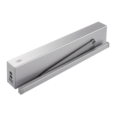
Provia QDC 311 User manual

INSTALLATION INSTRUCTIONS
NON-RESIDENTIAL ENTRY DOOR
STANLEY®CLOSER HARDWARE
(QDC 311 AND QDC 312 HOLD OPEN)
* Find QR Codes inside for additional information,
helpful installation tips and videos.
Contact the local recycling waste management center for waste disposal in the area.
Always check local waste requirements and carefully dispose of waste in accordance
with Federal and other regulations.
Homes built before 1978 may contain lead paint. All replacement installations must
comply with the U.S. EPA’s Lead-Based Paint Renovation, Repair, and Painting
Program (RRP Rule). Read more about the RRP Rule and lead-safe work practices, on
the U.S. EPA’s website at: www.epa.gov/lead
Option A – Regular Arm Installation
Top Jamb Installation
Option B –
Machine X2
Machine X4
Machine X4
Wood X2
Wood X4
Wood X4
Optional
cover
(a)
screw.
(c)
(e)
(b)
(d)
(f)
(g) (h)
(i) (j)
X1
X1
X1
X1
L
R
S
S
R
L
L
R
S
S
R
L
S
R
L
ATTENTION!
YOU CAN ALSO SCAN
THE PACKAGING QR CODE
TO ACCESS THIS DOCUMENT
Printed instructions included
with each product will be
phased out in the
near future

1
GETTING STARTED
IMPORTANT NOTES BEFORE YOU BEGIN
• Inspect your package for any visible damages to the product. In addition, double check your paperwork
with label on product(s) and verify all information is a match. Open packaging to confirm order was shipped
complete. If damages or irregularities are found, please document with pictures and call
Customer Service, 1-800-669-4711.
• If you have ordered optional items, verify that they are included in packaging contents. This includes checking
for multiple packages (For example, 1 of 2 and 2 of 2).
• For additional information and helpful videos, visit our 'Homepage for Installers' by
scanning the Quick Reference Code shown, using your QR Code Scanner App.
• Tape Measure
• Pencil
• Drill and Drill Bits
•Level
• 1⁄4"-20 Tap and #7 Drill Bit
•Screwdriver
TOOLS & MATERIALS YOU WILL NEED
REMEMBER: ALWAYS USE THE APPROPRIATE PERSONAL PROTECTIVE EQUIPMENT.
Read these instructions carefully before starting installation. Product warranty does not cover damages
resulting from improper installation.

2
This document is to assist with specific instruction for the installation of
Stanley®Closer Hardware, Model QDC 311or Model QDC 312 Hold Open
to a ProVia®Non-Residential Door. This instruction provides (3) installation options.
Refer to the following pages for the installation procedure required:
IMPORTANT DOCUMENT INFORMATION
Option A – Regular Arm Installation
Top Jamb Installation
Option B –
Machine X2
Machine X4
Machine X4
Wood X2
Wood X4
Wood X4
Optional
cover
(a)
screw.
(c)
(e)
(b)
(d)
(f)
(g) (h)
(i) (j)
X1
X1
X1
X1
L
R
S
S
R
L
L
R
S
S
R
L
S
R
L
PUSH to OPEN
Option A – Regular Arm Installation
Top Jamb Installation
Option B –
Machine X2
Machine X4
Machine X4
Wood X2
Wood X4
Wood X4
Optional
cover
(a)
screw.
(c)
(e)
(b)
(d)
(f)
(g) (h)
(i) (j)
X1
X1
X1
X1
L
R
S
S
R
L
L
R
S
S
R
L
S
R
L
PUSH to OPEN
Option A – Regular Arm Installation
Top Jamb Installation
Option B –
Machine X2
Machine X4
Machine X4
Wood X2
Wood X4
Wood X4
Optional
cover
(a)
screw.
(c)
(e)
(b)
(d)
(f)
(g) (h)
(i) (j)
X1
X1
X1
X1
L
R
S
S
R
L
L
R
S
S
R
L
S
R
L
PULL to OPEN
QDC 311 Closer Installation Screw Packs and Part
Identification, Page 3
QDC 312 Hold Open Closer Installation Screw Packs and
Part Identification, Page 4
Section A - Parallel Arm Installation for Push Side Mount,
Pages 5 - 6
Section B - Top Jamb Installation for Push Side Mount,
Pages 7 - 8
Section C - Regular Arm Installation for Pull Side Mount,
Pages 9 - 10
Section D - Door Closer Adjustments, Page 11
Option A – Regular Arm Installation
Top Jamb Installation
Option B –
Machine X2
Machine X4
Machine X4
Wood X2
Wood X4
Wood X4
Optional
cover
(a)
screw.
(c)
(e)
(b)
(d)
(f)
(g) (h)
(i) (j)
X1
X1
X1
X1
L
R
S
S
R
L
L
R
S
S
R
L
S
R
L
Option A – Regular Arm Installation
Top Jamb Installation
Option B –
Machine X2
Machine X4
Machine X4
Wood X2
Wood X4
Wood X4
Optional
cover
(a)
screw.
(c)
(e)
(b)
(d)
(f)
(g) (h)
(i) (j)
X1
X1
X1
X1
L
R
S
S
R
L
L
R
S
S
R
L
S
R
L
•
•
•
•
•
•

3
QDC 311 CLOSER INSTALLATION SCREW PACKS
AND PART IDENTIFICATION
Closer Installation Screw Pack (Stanley provided, large bag)
Option A – Regular Arm Installation
Top Jamb Installation
Option B –
Machine X2
Machine X4
Machine X4
Wood X2
Wood X4
Wood X4
Optional
cover
(a)
screw.
(c)
(e)
(b)
(d)
(f)
(g) (h)
(i) (j)
X1
X1
X1
X1
L
R
S
S
R
L
L
R
S
S
R
L
S
R
L
Option A – Regular Arm Installation
Top Jamb Installation
Option B –
Machine X2
Machine X4
Machine X4
Wood X2
Wood X4
Wood X4
Optional
cover
(a)
screw.
(c)
(e)
(b)
(d)
(f)
(g) (h)
(i) (j)
X1
X1
X1
X1
L
R
S
S
R
L
L
R
S
S
R
L
S
R
L
Parallel Bracket
(For parallel arm
installation only)
Arm Shoe
(For top jamb or regular
arm installation)
Closer Body
Speed
Adjusting Valves
Main Arm
Forearm
Back Check
Adjusting Valve
Power
Adjusting Valve
Closer Pinion
Option A – Regular Arm Installation
Top Jamb Installation
Option B –
Machine X2
Machine X4
Machine X4
Wood X2
Wood X4
Wood X4
Optional
cover
(a)
screw.
(c)
(e)
(b)
(d)
(f)
(g) (h)
(i) (j)
X1
X1
X1
X1
L
R
S
S
R
L
L
R
S
S
R
L
S
R
L
Option A – Regular Arm Installation
Top Jamb Installation
Option B –
Machine X2
Machine X4
Machine X4
Wood X2
Wood X4
Wood X4
Optional
cover
(a)
screw.
(c)
(e)
(b)
(d)
(f)
(g) (h)
(i) (j)
X1
X1
X1
X1
L
R
S
S
R
L
L
R
S
S
R
L
S
R
L
Pan Head
Machine Screws
(Arm shoe install to steel)
Flat Head
Machine screws
(Closer install to steel)
Hex Screw
w/ Lock Washer
(Main arm to pinion)
Pan Head
Wood Screws
(Arm shoe install to wood or fiberglass)
Flat Head
Wood screws
(Closer install to wood or fiberglass)
Hex Screw
w/ Washer
(Forearm to main arm)
Option A – Regular Arm Installation
Top Jamb Installation
Option B –
Machine X2
Machine X4
Machine X4
Wood X2
Wood X4
Wood X4
Optional
cover
(a)
screw.
(c)
(e)
(b)
(d)
(f)
(g) (h)
(i) (j)
X1
X1
X1
X1
L
R
S
S
R
L
L
R
S
S
R
L
S
R
L
Option A – Regular Arm Installation
Top Jamb Installation
Option B –
Machine X2
Machine X4
Machine X4
Wood X2
Wood X4
Wood X4
Optional
cover
(a)
screw.
(c)
(e)
(b)
(d)
(f)
(g) (h)
(i) (j)
X1
X1
X1
X1
L
R
S
S
R
L
L
R
S
S
R
L
S
R
L
Flat Head
Machine Screws
(Parallel bracket install to steel)
Flat Head
Wood Screws
(Parallel bracket install to wd. or fb.)
Option A – Regular Arm Installation
Top Jamb Installation
Option B –
Machine X2
Machine X4
Machine X4
Wood X2
Wood X4
Wood X4
Optional
cover
(a)
screw.
(c)
(e)
(b)
(d)
(f)
(g) (h)
(i) (j)
X1
X1
X1
X1
L
R
S
S
R
L
L
R
S
S
R
L
S
R
L
Option A – Regular Arm Installation
Top Jamb Installation
Option B –
Machine X2
Machine X4
Machine X4
Wood X2
Wood X4
Wood X4
Optional
cover
(a)
screw.
(c)
(e)
(b)
(d)
(f)
(g) (h)
(i) (j)
X1
X1
X1
X1
L
R
S
S
R
L
L
R
S
S
R
L
S
R
L
Pan Head
Self-Taping Screws
(Arm shoe install to all types)
Flat Head
Self-Taping Screws
(Closer install to all types)
Hex Wrench
(Power adjustments)
(2)
(4)
(1)
(2)
(4)
(1)
(2)
(4)
(1)
Option A – Regular Arm Installation
Top Jamb Installation
Option B –
Machine X2
Machine X4
Machine X4
Wood X2
Wood X4
Wood X4
Optional
cover
(a)
screw.
(c)
(e)
(b)
(d)
(f)
(g) (h)
(i) (j)
X1
X1
X1
X1
L
R
S
S
R
L
L
R
S
S
R
L
S
R
L
Option A – Regular Arm Installation
Top Jamb Installation
Option B –
Machine X2
Machine X4
Machine X4
Wood X2
Wood X4
Wood X4
Optional
cover
(a)
screw.
(c)
(e)
(b)
(d)
(f)
(g) (h)
(i) (j)
X1
X1
X1
X1
L
R
S
S
R
L
L
R
S
S
R
L
S
R
L
Option A – Regular Arm Installation
Top Jamb Installation
Option B –
Machine X2
Machine X4
Machine X4
Wood X2
Wood X4
Wood X4
Optional
cover
(a)
screw.
(c)
(e)
(b)
(d)
(f)
(g) (h)
(i) (j)
X1
X1
X1
X1
L
R
S
S
R
L
L
R
S
S
R
L
S
R
L
Option A – Regular Arm Installation
Top Jamb Installation
Option B –
Machine X2
Machine X4
Machine X4
Wood X2
Wood X4
Wood X4
Optional
cover
(a)
screw.
(c)
(e)
(b)
(d)
(f)
(g) (h)
(i) (j)
X1
X1
X1
X1
L
R
S
S
R
L
L
R
S
S
R
L
S
R
L
Option A – Regular Arm Installation
Top Jamb Installation
Option B –
Machine X2
Machine X4
Machine X4
Wood X2
Wood X4
Wood X4
Optional
cover
(a)
screw.
(c)
(e)
(b)
(d)
(f)
(g) (h)
(i) (j)
X1
X1
X1
X1
L
R
S
S
R
L
L
R
S
S
R
L
S
R
L
Option A – Regular Arm Installation
Top Jamb Installation
Option B –
Machine X2
Machine X4
Machine X4
Wood X2
Wood X4
Wood X4
Optional
cover
(a)
screw.
(c)
(e)
(b)
(d)
(f)
(g) (h)
(i) (j)
X1
X1
X1
X1
L
R
S
S
R
L
L
R
S
S
R
L
S
R
L
Parallel Bracket Installation Screw Pack (Stanley provided, small bag)
Option A – Regular Arm Installation
Top Jamb Installation
Option B –
Machine X2
Machine X4
Machine X4
Wood X2
Wood X4
Wood X4
Optional
cover
(a)
screw.
(c)
(e)
(b)
(d)
(f)
(g) (h)
(i) (j)
X1
X1
X1
X1
L
R
S
S
R
L
L
R
S
S
R
L
S
R
L
(4) (4) Screw w/ Washer
(Forearm to bracket install)
(1)
Wood Frame Unit Screw Pack, Part # P-HW-ACCSZN-00 (ProVia provided with wood frame units only)
#14 x 3" Pan Head Screws
(Arm shoe install to wood jamb)
(2) #14 x 3" Flat Head Screws
(Parallel bracket install to wood jamb)
(4)
Through Bolt Screw Pack (Stanley provided) - DISCARD!
Option A – Regular Arm Installation
Top Jamb Installation
Option B –
Machine X2
Machine X4
Machine X4
Wood X2
Wood X4
Wood X4
Optional
cover
(a)
screw.
(c)
(e)
(b)
(d)
(f)
(g) (h)
(i) (j)
X1
X1
X1
X1
L
R
S
S
R
L
L
R
S
S
R
L
S
R
L
QDC 311 PART IDENTIFICATION
DO NOT USE for installation to a ProVia door.
ALL ProVia door units are internally reinforced.
Through Sleeve with Screw
(4)

4
Flat Head
Machine screws
(Closer install)
Flat Head
Self-Taping Screws
(Optional Cover)
Oval Head
Wood screws
(Closer install)
Hex Wrench
(Power adjustments)
Flat Head
Self-Taping Screws
(Closer install)
(4)
(1)
(4)
(1)
(4)
Option A – Regular Arm Installation
Top Jamb Installation
Option B –
Machine X2
Machine X4
Machine X4
Wood X2
Wood X4
Wood X4
Optional
cover
(a)
screw.
(c)
(e)
(b)
(d)
(f)
(g) (h)
(i) (j)
X1
X1
X1
X1
L
R
S
S
R
L
L
R
S
S
R
L
S
R
L
Option A – Regular Arm Installation
Top Jamb Installation
Option B –
Machine X2
Machine X4
Machine X4
Wood X2
Wood X4
Wood X4
Optional
cover
(a)
screw.
(c)
(e)
(b)
(d)
(f)
(g) (h)
(i) (j)
X1
X1
X1
X1
L
R
S
S
R
L
L
R
S
S
R
L
S
R
L
Option A – Regular Arm Installation
Top Jamb Installation
Option B –
Machine X2
Machine X4
Machine X4
Wood X2
Wood X4
Wood X4
Optional
cover
(a)
screw.
(c)
(e)
(b)
(d)
(f)
(g) (h)
(i) (j)
X1
X1
X1
X1
L
R
S
S
R
L
L
R
S
S
R
L
S
R
L
Option A – Regular Arm Installation
Top Jamb Installation
Option B –
Machine X2
Machine X4
Machine X4
Wood X2
Wood X4
Wood X4
Optional
cover
(a)
screw.
(c)
(e)
(b)
(d)
(f)
(g) (h)
(i) (j)
X1
X1
X1
X1
L
R
S
S
R
L
L
R
S
S
R
L
S
R
L
Option A – Regular Arm Installation
Top Jamb Installation
Option B –
Machine X2
Machine X4
Machine X4
Wood X2
Wood X4
Wood X4
Optional
cover
(a)
screw.
(c)
(e)
(b)
(d)
(f)
(g) (h)
(i) (j)
X1
X1
X1
X1
L
R
S
S
R
L
L
R
S
S
R
L
S
R
L
Flat Head
Machine Screws
(Parallel bracket install)
Locknut
(Arm assembly to
bracket install)
Oval Head
Wood Screws
(Parallel bracket install)
Hex Wrench
(6)
(2)
(4)
(1)
(1)
Option A – Regular Arm Installation
Top Jamb Installation
Option B –
Machine X2
Machine X4
Machine X4
Wood X2
Wood X4
Wood X4
Optional
cover
(a)
screw.
(c)
(e)
(b)
(d)
(f)
(g) (h)
(i) (j)
X1
X1
X1
X1
L
R
S
S
R
L
L
R
S
S
R
L
S
R
L
Option A – Regular Arm Installation
Top Jamb Installation
Option B –
Machine X2
Machine X4
Machine X4
Wood X2
Wood X4
Wood X4
Optional
cover
(a)
screw.
(c)
(e)
(b)
(d)
(f)
(g) (h)
(i) (j)
X1
X1
X1
X1
L
R
S
S
R
L
L
R
S
S
R
L
S
R
L
Option A – Regular Arm Installation
Top Jamb Installation
Option B –
Machine X2
Machine X4
Machine X4
Wood X2
Wood X4
Wood X4
Optional
cover
(a)
screw.
(c)
(e)
(b)
(d)
(f)
(g) (h)
(i) (j)
X1
X1
X1
X1
L
R
S
S
R
L
L
R
S
S
R
L
S
R
L
Option A – Regular Arm Installation
Top Jamb Installation
Option B –
Machine X2
Machine X4
Machine X4
Wood X2
Wood X4
Wood X4
Optional
cover
(a)
screw.
(c)
(e)
(b)
(d)
(f)
(g) (h)
(i) (j)
X1
X1
X1
X1
L
R
S
S
R
L
L
R
S
S
R
L
S
R
L
Option A – Regular Arm Installation
Top Jamb Installation
Option B –
Machine X2
Machine X4
Machine X4
Wood X2
Wood X4
Wood X4
Optional
cover
(a)
screw.
(c)
(e)
(b)
(d)
(f)
(g) (h)
(i) (j)
X1
X1
X1
X1
L
R
S
S
R
L
L
R
S
S
R
L
S
R
L
Wood Frame Unit Screw Pack, Part # P-HW-ACCSZN-00 (ProVia provided with wood frame units only)
#14 x 3" Pan Head Screws
(Arm shoe install to wood frame)
(2) #14 x 3" Flat Head Screws
(Parallel bracket install to wood frame)
(4)
Option A – Regular Arm Installation
Top Jamb Installation
Option B –
Machine X2
Machine X4
Machine X4
Wood X2
Wood X4
Wood X4
Optional
cover
(a)
screw.
(c)
(e)
(b)
(d)
(f)
(g) (h)
(i) (j)
X1
X1
X1
X1
L
R
S
S
R
L
L
R
S
S
R
L
S
R
L
QDC 312 HOLD OPEN CLOSER INSTALLATION SCREW PACKS
AND PART IDENTIFICATION
Closer Installation Screw Pack (Stanley provided, large bag)
Parallel Bracket Installation Screw Pack (Stanley provided, small bag)
QDC 312 PART IDENTIFICATION
Arm Assembly
Parallel Bracket
(For parallel arm
installation only)
Back Check
Adjusting Valve
Power
Adjusting Valve
Closer Body
Speed
Adjusting Valves
Main Arm
Closer Pinion Hold Open Nut
Hex Screw
w/ Lock Washer
(Main arm to pinion)
Option A – Regular Arm Installation
Top Jamb Installation
Option B –
Machine X2
Machine X4
Machine X4
Wood X2
Wood X4
Wood X4
Optional
cover
(a)
screw.
(c)
(e)
(b)
(d)
(f)
(g) (h)
(i) (j)
X1
X1
X1
X1
L
R
S
S
R
L
L
R
S
S
R
L
S
R
L
Through Bolt Screw Pack (Stanley provided) - DISCARD!
DO NOT USE for installation to a ProVia door.
ALL ProVia door units are internally reinforced.
Through Sleeve with Screw
(4)

5
A. PARALLEL ARM INSTALLATION FOR PUSH-SIDE MOUNT
Determine the door handing and degree of
opening required for the closer installation.
Refer to the correct 'Dimension Reference
Chart' above and to the appropriate Figure
A.1 or A.2 for the dimensions required.
(Figure A.1)
(Figure A.2)
LEFT Hand Out-Swing Door
Option A – Regular Arm Installation
Top Jamb Installation
Option B –
Machine X2
Machine X4
Machine X4
Wood X2
Wood X4
Wood X4
Optional
cover
(a)
screw.
(c)
(e)
(b)
(d)
(f)
(g) (h)
(i) (j)
X1
X1
X1
X1
L
R
S
S
R
L
L
R
S
S
R
L
S
R
L
Option A – Regular Arm Installation
Top Jamb Installation
Option B –
Machine X2
Machine X4
Machine X4
Wood X2
Wood X4
Wood X4
Optional
cover
(a)
screw.
(c)
(e)
(b)
(d)
(f)
(g) (h)
(i) (j)
X1
X1
X1
X1
L
R
S
S
R
L
L
R
S
S
R
L
S
R
L
C
L
'A'
1⁄2"
3/4"
'B' 91⁄16"
Parallel bracket
required
PUSH
to
OPEN
Hinge
or Pivot
Plan ViewElevation View
QDC 311 DIMENSION REFERENCE CHART
Door Opening Dim. 'A' Dim. 'B' Dim. 'C'
To 100° 91⁄4" 75⁄8" 31⁄4"
100° to 120° 73⁄4" 61⁄8" 31⁄4"
121° to 180° 53⁄4" 41⁄8" 31⁄4"
RIGHT Hand Out-Swing Door
Parallel bracket
required
Option A – Regular Arm Installation
Top Jamb Installation
Option B –
Machine X2
Machine X4
Machine X4
Wood X2
Wood X4
Wood X4
Optional
cover
(a)
screw.
(c)
(e)
(b)
(d)
(f)
(g) (h)
(i) (j)
X1
X1
X1
X1
L
R
S
S
R
L
L
R
S
S
R
L
S
R
L
PUSH
to
OPEN
Option A – Regular Arm Installation
Top Jamb Installation
Option B –
Machine X2
Machine X4
Machine X4
Wood X2
Wood X4
Wood X4
Optional
cover
(a)
screw.
(c)
(e)
(b)
(d)
(f)
(g) (h)
(i) (j)
X1
X1
X1
X1
L
R
S
S
R
L
L
R
S
S
R
L
S
R
L
Plan ViewElevation View
C
L
Hinge
or Pivot
'A'
1⁄2"
3/4"
'B'
91⁄16"
1Use dimensions as indicated on the Elevation
View to locate and mark the center of all (4)
closer screw holes on door slab. (Fig A.1 or A.2)
Parallel bracket
Closer
Closer
Parallel bracket
2Use dimensions as indicated on the Plan
View to locate and mark (1) parallel bracket
screw hole on underside of frame header.
Use bracket as template to locate remaining
screw hole locations. (Figure A.1 or A.2)
3Pre-drill all marked screw hole locations on
door slab and frame header. For wood or
fiberglass, use a 7⁄32" drill bit. For steel, drill
and tap #7 for 1⁄4"-20 machine screws.
4Install the parallel bracket to frame header
using the appropriate screws provided.
NOTE: For wood jamb application only, insert
wood blocking to fill space between jamb and
header at bracket location. Use ProVia wood
screws provided.
5Position and install closer to the door slab.
The speed adjustment valve MUST BE
positioned AWAY from the hinge-side. Use
the appropriate screws provided.
NOTE: DO NOT USE THROUGH BOLTS to
install closer to the door slab.
'C'
'C'
QDC 312 DIMENSION REFERENCE CHART
Door Opening Dim. 'A' Dim. 'B' Dim. 'C'
To 100° 91⁄4" 75⁄8" 31⁄2"
100° to 120° 73⁄4" 61⁄8" 31⁄2"
121° to 180° 53⁄4" 41⁄8" 31⁄2"

6
(Figure A.4)
(Figure A.5)
(Figure A.3)
A. PARALLEL ARM INSTALLATION FOR PUSH-SIDE MOUNT
6Set main arm on top closer pinion,
PARALLEL to door slab. Use wrench to
rotate bottom closer pinion approximately
45° towards hinge-side. As bottom closer
pinion is rotated, main arm will slide onto top
pinion. Use the 'L' and 'R' marked on main
arm to determine direction of swing. Main
arm will point away from hinge-side. Refer to
Figure A.3 for illustration of handing. Tightly
secure using (1) 3⁄4" hex screw with lock
washer. (Figure A.3 & A.4)
8For QDC 311, remove the arm shoe from the
forearm. Install and secure the forearm to
the parallel bracket pin using screw provided.
Open door to allow the forearm to slide into
the main arm. Loosely fasten the forearm
to the main arm using (1) 1⁄2" hex screw with
washer. Close door, rotate main arm until 1"
away from door slab. Tighten hex screw to
secure forearm in place.
For QDC 312, Install and secure the arm
assembly to the parallel bracket pin using
screw provided. (For LEFT hand door,
position the hold open nut down. For RIGHT
hand door, position the hold open nut up.)
Open door to allow the main arm to slide into
the arm assembly. Close door, rotate main
arm until 1" away from door slab. Tighten set
screw to secure the arm assembly in place.
(Figure A.5)
7
8Adjust door closing speed and power. Refer
to Section D, 'Closer Adjustments' for
instruction.
8
9Snap the pinion cap cover onto the bottom
closer pin or install the QDC 312 optional
cover with screw provided.
Option A – Regular Arm Installation
Top Jamb Installation
Option B –
Machine X2
Machine X4
Machine X4
Wood X2
Wood X4
Wood X4
Optional
cover
(a)
screw.
(c)
(e)
(b)
(d)
(f)
(g) (h)
(i) (j)
X1
X1
X1
X1
L
R
S
S
R
L
L
R
S
S
R
L
S
R
L
Main Arm Installation
(Left Hand Out-Swing Shown)
Option A – Regular Arm Installation
Top Jamb Installation
Option B –
Machine X2
Machine X4
Machine X4
Wood X2
Wood X4
Wood X4
Optional
cover
(a)
screw.
(c)
(e)
(b)
(d)
(f)
(g) (h)
(i) (j)
X1
X1
X1
X1
L
R
S
S
R
L
L
R
S
S
R
L
S
R
L
LH Out-Swing RH Out-Swing
Option A – Regular Arm Installation
Top Jamb Installation
Option B –
Machine X2
Machine X4
Machine X4
Wood X2
Wood X4
Wood X4
Optional
cover
(a)
screw.
(c)
(e)
(b)
(d)
(f)
(g) (h)
(i) (j)
X1
X1
X1
X1
L
R
S
S
R
L
L
R
S
S
R
L
S
R
L
Top view of main
arm placed parallel
to door slab
Hinge-Side
Hinge-Side
Set main arm on top of closer pin,
PARALLEL to door slab and away from hinge-side
CORRECT Main Arm Installation
CORRECT
Main arm is installed
parallel to slab. Closer is
loaded under pressure, will
fully close door slab.
NOT CORRECT
Main arm is installed
angled away from slab.
Closer has little pressure,
will not fully close door
slab.
Option A – Regular Arm Installation
Top Jamb Installation
Option B –
Machine X2
Machine X4
Machine X4
Wood X2
Wood X4
Wood X4
Optional
cover
(a)
screw.
(c)
(e)
(b)
(d)
(f)
(g) (h)
(i) (j)
X1
X1
X1
X1
L
R
S
S
R
L
L
R
S
S
R
L
S
R
L
Option A – Regular Arm Installation
Top Jamb Installation
Option B –
Machine X2
Machine X4
Machine X4
Wood X2
Wood X4
Wood X4
Optional
cover
(a)
screw.
(c)
(e)
(b)
(d)
(f)
(g) (h)
(i) (j)
X1
X1
X1
X1
L
R
S
S
R
L
L
R
S
S
R
L
S
R
L
Door Slab Door Slab
Closer with parallel arm installation is
COMPLETE.
QDC 312 Hold Open Arm Assembly
to Bracket
LEFT Hand
Position nut down
RIGHT Hand
Position nut up
Bracket Bracket
Arm Assembly Arm Assembly

7
B.TOP JAMB INSTALLATION FOR PUSH-SIDE MOUNT
Determine the door handing and
degree of opening required for the
closer installation. Refer to the correct
'Dimension Reference Chart' above and
to the appropriate Figure B.1 or B.2 for
the dimensions required to locate closer.
QDC 311 DIMENSION REFERENCE CHART
Door Opening Dim. 'A'
To 100° 71⁄2"
100° to 120° 6"
121° to 180° 31⁄2"
3Pre-drill all marked screw hole locations on
door slab and frame header. For wood or
fiberglass, use a 7⁄32" drill bit. For steel, drill
and tap #7 for 1⁄4"-20 machine screws.
4Position and install the closer onto the frame
header. The speed adjustment valve MUST
BE positioned TOWARDS the hinge-side.
Use the appropriate screws provided.
NOTE: For wood jamb application only, wood
blocking may be needed. Use the ProVia
wood jamb screws provided.
(Figure B.1)
(Figure B.2)
LEFT Hand OUT-Swing Door Elevation View
Option A – Regular Arm Installation
Top Jamb Installation
Option B –
Machine X2
Machine X4
Machine X4
Wood X2
Wood X4
Wood X4
Optional
cover
(a)
screw.
(c)
(e)
(b)
(d)
(f)
(g) (h)
(i) (j)
X1
X1
X1
X1
L
R
S
S
R
L
L
R
S
S
R
L
S
R
L
Option A – Regular Arm Installation
Top Jamb Installation
Option B –
Machine X2
Machine X4
Machine X4
Wood X2
Wood X4
Wood X4
Optional
cover
(a)
screw.
(c)
(e)
(b)
(d)
(f)
(g) (h)
(i) (j)
X1
X1
X1
X1
L
R
S
S
R
L
L
R
S
S
R
L
S
R
L
3/4"
'A'
6"
Arm shoe
required
PUSH
to
OPEN
RIGHT Hand OUT-Swing Door Elevation View
Arm shoe
required
Closer
C
L
Hinge
or Pivot
91⁄16"
Option A – Regular Arm Installation
Top Jamb Installation
Option B –
Machine X2
Machine X4
Machine X4
Wood X2
Wood X4
Wood X4
Optional
cover
(a)
screw.
(c)
(e)
(b)
(d)
(f)
(g) (h)
(i) (j)
X1
X1
X1
X1
L
R
S
S
R
L
L
R
S
S
R
L
S
R
L
PUSH
to
OPEN
1/2"
11/2"
Option A – Regular Arm Installation
Top Jamb Installation
Option B –
Machine X2
Machine X4
Machine X4
Wood X2
Wood X4
Wood X4
Optional
cover
(a)
screw.
(c)
(e)
(b)
(d)
(f)
(g) (h)
(i) (j)
X1
X1
X1
X1
L
R
S
S
R
L
L
R
S
S
R
L
S
R
L
3/4"
'A'
6"
Closer
C
L
Hinge
or Pivot
91⁄16"
1/2"
11/2"
QDC 312 DIMENSION REFERENCE CHART
Door Opening Dim. 'A' Hold Degree
To 100° 75⁄8" 90° - 100°
100° to 120° 61⁄8" 101° - 130°
121° to 180° 41⁄8" 131° - 180°
1Use dimensions as indicated on the
Elevation View to locate and mark the
center of all (4) closer screw holes on frame
header. (Figure B.1 or B.2)
2Use dimensions as indicated on the
Elevation View to locate and mark (1) arm
shoe screw hole on door slab. Use bracket
as template to locate remaining screw hole
location. (Figure B.1 or B.2)
Option A – Regular Arm Installation
Top Jamb Installation
Option B –
Machine X2
Machine X4
Machine X4
Wood X2
Wood X4
Wood X4
Optional
cover
(a)
screw.
(c)
(e)
(b)
(d)
(f)
(g) (h)
(i) (j)
X1
X1
X1
X1
L
R
S
S
R
L
L
R
S
S
R
L
S
R
L
Option A – Regular Arm Installation
Top Jamb Installation
Option B –
Machine X2
Machine X4
Machine X4
Wood X2
Wood X4
Wood X4
Optional
cover
(a)
screw.
(c)
(e)
(b)
(d)
(f)
(g) (h)
(i) (j)
X1
X1
X1
X1
L
R
S
S
R
L
L
R
S
S
R
L
S
R
L

8
5For QDC 311, Install the arm shoe with
forearm onto the door slab using the
appropriate screws provided.
For QDC 312, Install the arm assembly onto
the door slab using the appropriate screws
provided. For LEFT hand door, position the
hold open nut down. For RIGHT hand door,
position the hold open nut up. (Figure B.3)
NOTE: DO NOT USE THROUGH BOLTS
to install arm shoe or arm assembly to
the door slab.
B.TOP JAMB INSTALLATION FOR PUSH-SIDE MOUNT
6Install main arm onto the bottom closer
pinion, PERPENDICULAR to the door slab.
Tightly secure using (1) 3⁄4" hex screw with
lock washer. (Figure B.4)
8Adjust door closing speed and power. Refer
to Section D, 'Closer Adjustments' for
instruction.
8
7For QDC 311, open door to allow the
forearm to slide into the main arm. Loosely
fasten the forearm to the main arm using
(1) 1⁄2" hex screw with washer. Close door,
rotate main arm until the FOREARM is
PERPENDICULAR to door slab. Tighten
hex screw to secure forearm in place.
(Figure B.5)
For QDC 312, open door to allow the
main arm to slide into the arm assembly.
Close door, rotate main arm until the ARM
ASSEMBLY is PERPENDICULAR to door
slab. Tighten set screw to secure the arm
assembly in place.
Option A – Regular Arm Installation
Top Jamb Installation
Option B –
Machine X2
Machine X4
Machine X4
Wood X2
Wood X4
Wood X4
Optional
cover
(a)
screw.
(c)
(e)
(b)
(d)
(f)
(g) (h)
(i) (j)
X1
X1
X1
X1
L
R
S
S
R
L
L
R
S
S
R
L
S
R
L
Door Frame
Option A – Regular Arm Installation
Top Jamb Installation
Option B –
Machine X2
Machine X4
Machine X4
Wood X2
Wood X4
Wood X4
Optional
cover
(a)
screw.
(c)
(e)
(b)
(d)
(f)
(g) (h)
(i) (j)
X1
X1
X1
X1
L
R
S
S
R
L
L
R
S
S
R
L
S
R
L
QDC 311 Forearm Installation
Rotate forearm perpendicular to door slab
Secure forearm to main arm using
1⁄2" hex screw with washer
(Figure B.5)
(Figure B.3)
(Figure B.4)
QDC 312 Hold Open Arm Assembly
LEFT Hand
Position nut down
RIGHT Hand
Position nut up
Arm Assembly
CORRECT Main Arm Installation
CORRECT
Main arm is installed
perpendicular to slab.
Closer is pre-loaded, will
fully close door slab.
NOT CORRECT
Main arm is installed
angled away. Closer has
little pressure, will not
fully close door slab.
Option A – Regular Arm Installation
Top Jamb Installation
Option B –
Machine X2
Machine X4
Machine X4
Wood X2
Wood X4
Wood X4
Optional
cover
(a)
screw.
(c)
(e)
(b)
(d)
(f)
(g) (h)
(i) (j)
X1
X1
X1
X1
L
R
S
S
R
L
L
R
S
S
R
L
S
R
L
Door Frame
Arm Assembly
9Snap the pinion cap cover onto the bottom
closer pin or install the QDC 312 optional
cover with screw provided.
Closer with top jamb installation is
COMPLETE.

9
C. REGULAR ARM INSTALLATION FOR PULL-SIDE MOUNT
Determine the door handing and
degree of opening required for the
closer installation. Refer to the correct
'Dimension Reference Chart' above and
to the appropriate Figure C.1 or C.2 for
the dimensions required to locate closer.
QDC 311 DIMENSION REFERENCE CHART
Door Opening Dim. 'A'
To 100° 71⁄2"
100° to 120° 6"
121° to 180° 31⁄2"
3Pre-drill all marked screw hole locations on
door slab and frame header. For wood or
fiberglass, use a 7⁄32" drill bit. For steel, drill
and tap #7 for 1⁄4"-20 machine screws.
4Position and install the closer onto the door
slab. The speed adjustment valve MUST BE
positioned TOWARDS the hinge-side. Use
the appropriate screws provided.
NOTE: DO NOT USE THROUGH BOLTS to
install arm shoe to the door slab.
(Figure C.1)
(Figure C.2)
RIGHT Hand In-Swing Door Elevation View
Option A – Regular Arm Installation
Top Jamb Installation
Option B –
Machine X2
Machine X4
Machine X4
Wood X2
Wood X4
Wood X4
Optional
cover
(a)
screw.
(c)
(e)
(b)
(d)
(f)
(g) (h)
(i) (j)
X1
X1
X1
X1
L
R
S
S
R
L
L
R
S
S
R
L
S
R
L
Option A – Regular Arm Installation
Top Jamb Installation
Option B –
Machine X2
Machine X4
Machine X4
Wood X2
Wood X4
Wood X4
Optional
cover
(a)
screw.
(c)
(e)
(b)
(d)
(f)
(g) (h)
(i) (j)
X1
X1
X1
X1
L
R
S
S
R
L
L
R
S
S
R
L
S
R
L
11/4"
3/4"
'A' 91⁄16"
Arm shoe
required
PULL
to
OPEN
LEFT Hand In-Swing Door Elevation View
Arm shoe
required
Closer
C
L
Hinge
or Pivot
Option A – Regular Arm Installation
Top Jamb Installation
Option B –
Machine X2
Machine X4
Machine X4
Wood X2
Wood X4
Wood X4
Optional
cover
(a)
screw.
(c)
(e)
(b)
(d)
(f)
(g) (h)
(i) (j)
X1
X1
X1
X1
L
R
S
S
R
L
L
R
S
S
R
L
S
R
L
PULL
to
OPEN
6"
7/8"
1/8"
Option A – Regular Arm Installation
Top Jamb Installation
Option B –
Machine X2
Machine X4
Machine X4
Wood X2
Wood X4
Wood X4
Optional
cover
(a)
screw.
(c)
(e)
(b)
(d)
(f)
(g) (h)
(i) (j)
X1
X1
X1
X1
L
R
S
S
R
L
L
R
S
S
R
L
S
R
L
11/4"
3/4"
'A'
91⁄16"
Closer
C
L
Hinge
or Pivot
6"
7/8"
1/8"
QDC 312 DIMENSION REFERENCE CHART
Door Opening Dim. 'A' Hold Degree
To 100° 75⁄8" 90° - 100°
100° to 120° 61⁄8" 101° - 130°
121° to 180° 41⁄8" 131° - 180°
1Use dimensions as indicated on the
Elevation View to locate and mark the center
of all (4) closer screw holes on the door
slab. (Figure C.1 or C.2)
2Use dimensions as indicated on the
Elevation View to locate and mark (1) arm
shoe screw hole on frame header. Use
bracket as template to locate remaining
screw hole location. (Figure C.1 or C.2)

10
C. REGULAR ARM INSTALLATION FOR PULL-SIDE MOUNT
Closer with regular arm installation is
COMPLETE.
Option A – Regular Arm Installation
Top Jamb Installation
Option B –
Machine X2
Machine X4
Machine X4
Wood X2
Wood X4
Wood X4
Optional
cover
(a)
screw.
(c)
(e)
(b)
(d)
(f)
(g) (h)
(i) (j)
X1
X1
X1
X1
L
R
S
S
R
L
L
R
S
S
R
L
S
R
L
Door Frame
QDC 311 Forearm Installation
Rotate forearm perpendicular to door slab
Secure forearm to main arm using
1⁄2" hex screw with washer
(Figure C.5)
(Figure C.3)
(Figure C.4)
QDC 312 Hold Open Arm Assembly
LEFT Hand
Position nut down
RIGHT Hand
Position nut up
Arm Assembly
CORRECT Main Arm Installation
CORRECT
Main arm is installed
perpendicular to slab.
Closer is pre-loaded, will
fully close door slab.
NOT CORRECT
Main arm is installed
angled away. Closer has
little pressure, will not
fully close door slab.
Option A – Regular Arm Installation
Top Jamb Installation
Option B –
Machine X2
Machine X4
Machine X4
Wood X2
Wood X4
Wood X4
Optional
cover
(a)
screw.
(c)
(e)
(b)
(d)
(f)
(g) (h)
(i) (j)
X1
X1
X1
X1
L
R
S
S
R
L
L
R
S
S
R
L
S
R
L
Door Frame
Arm Assembly
Option A – Regular Arm Installation
Top Jamb Installation
Option B –
Machine X2
Machine X4
Machine X4
Wood X2
Wood X4
Wood X4
Optional
cover
(a)
screw.
(c)
(e)
(b)
(d)
(f)
(g) (h)
(i) (j)
X1
X1
X1
X1
L
R
S
S
R
L
L
R
S
S
R
L
S
R
L
5For QDC 311, Install the arm shoe with
forearm onto frame header using the
appropriate screws provided.
For QDC 312, Install the arm assembly onto
frame header using the appropriate screws
provided. For LEFT hand door, position the
hold open nut down. For RIGHT hand door,
position the hold open nut up. (Figure C.3)
NOTE: For wood jamb application only, insert
wood blocking to fill space between jamb and
header at arm shoe or arm assembly location.
Use ProVia wood screws provided.
NOTE: DO NOT USE THROUGH BOLTS
to install arm shoe or arm assembly to the
door slab.
6Install main arm onto the top closer pinion,
PERPENDICULAR to the door slab. Tightly
secure using (1) 3⁄4" hex screw with lock
washer. (Figure C.4)
8Adjust door closing speed and power. Refer
to Section D, 'Closer Adjustments' for
instruction.
8
7For QDC 311, open door to allow the
forearm to slide into the main arm. Loosely
fasten the forearm to the main arm using
(1) 1⁄2" hex screw with washer. Close door,
rotate main arm until the FOREARM is
PERPENDICULAR to door slab. Tighten hex
screw to secure forearm in place. (Figure C.5)
For QDC 312, open door to allow the
main arm to slide into the arm assembly.
Close door, rotate main arm until the ARM
ASSEMBLY is PERPENDICULAR to door
slab. Tighten set screw to secure the arm
assembly in place.
9Snap the pinion cap cover onto the bottom
closer pin or install the QDC 312 optional
cover with screw provided.

2150 State Route 39, Sugarcreek, OH 44681
Phone: 330.852.4711 • Fax: 877.735.2057
provia.com
Version 1.1 · 12.17.2021 · © 2021 Provia · P-MK-61027
D. DOOR CLOSER ADJUSTMENTS
L
S
POWER ADJUSTMENT CHART
Door
Closer Size
Full Turn of Power
Adjusting Screw
Applicable Door Leaf Width Applicable Door Weight
Interior Exterior (Out-Swing)
1 - 4 32" 28" 33 to 56 LBS
2 - 2 36" 32" 56 to 99 LBS
3 0 (Preset) 42" 36" 99 to 143 LBS
4 + 3 48" 42" 143 to 187 LBS
5 + 6 54" 48" 187 to 264 LBS
6 + 10 58" 54" 264 to 330 LBS
L
S
Clockwise for Full Numbers (+)
Counter-Clockwise for Full Numbers (-)
Use 5⁄32" Hex Wrench
for this adjustment
Power Adjusting
Screw
Closer Elevation Views - Adjustment Screws and Valve Identification
Delayed Action
Adjusting Valve
Latch
Adjusting Valve
Sweep
Adjusting Valve
Back Check
Adjusting Valve
Power
Adjusting Screw
L
S
Opening Cycle Adjustment
L
S
Closing Cycle Adjustment
Increase opening tension
Decrease opening tension
Slower
Faster
Back Check
Opening
Delay
Sweep
Latch
*Please call Customer Service for additional installation inquiries at 1-800-669-4711.
NOTE: When closer is paired with a panic hardware exit device, closer adjustments will affect the exit device
latching process.
This manual suits for next models
1
Table of contents
