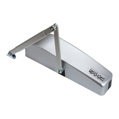
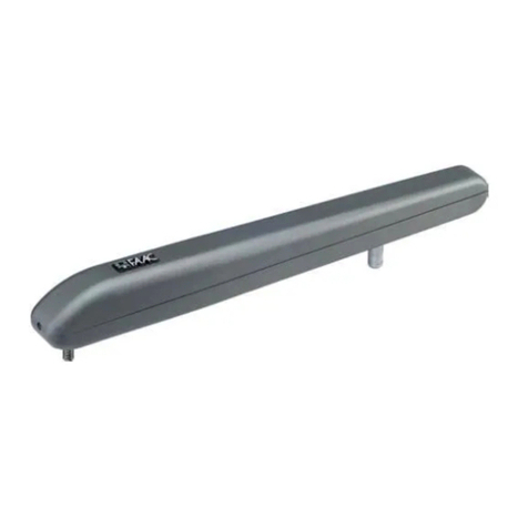
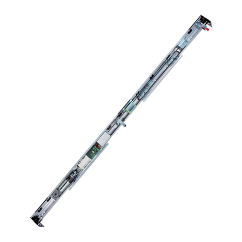
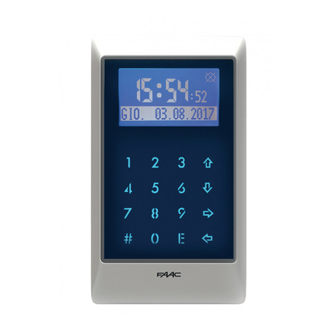
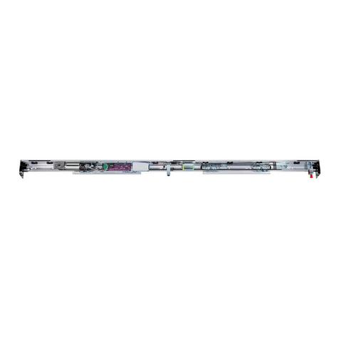
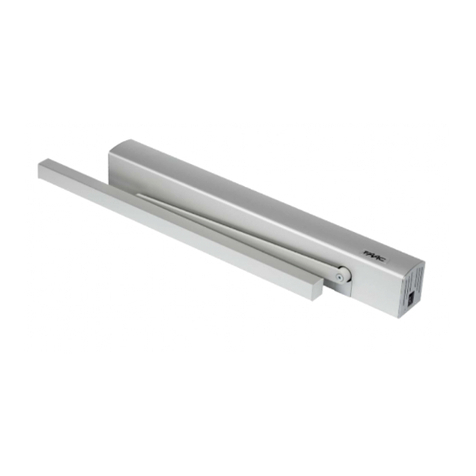
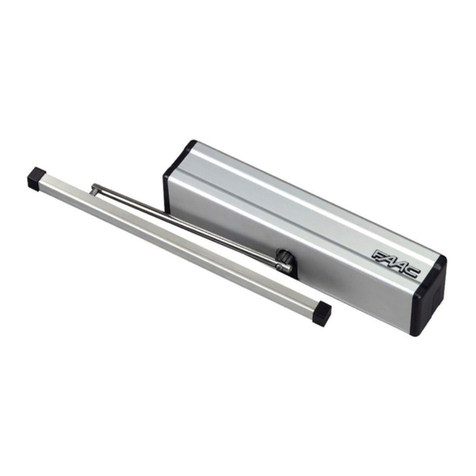
FAAC 950 BM User manual

950 BM
Swing Door Operator
(800) 878-7829
www.FastGateOpeners.com

2
FAAC MODEL 950 BM Door Operator
shielded
Fig. 2a
Fig. 3
1
122
Fig. 4 Fig. 4b
Fig. 4a
3
1
4
1
4
3
2
2
6
5
5
8
8
7
(800) 878-7829
www.FastGateOpeners.com

3
FAAC MODEL 950 BM Door Operator
Fig.5
Fig.6
(800) 878-7829
www.FastGateOpeners.com

4
FAAC MODEL 950 BM Door Operator
(*) Distance with standard extension.
If a greater distance between the
operator and the arm is required,
add the optional modular extensions.
Each modular extension increases
the standard height of 1 1/8 inches.
It is not rccommended to use more than
2 extensions.
TABLE A: LINTEL MOUNTING (PUSHING ARTICULATED ARM)
Dimensions in inches
(800) 878-7829
www.FastGateOpeners.com

5
FAAC MODEL 950 BM Door Operator
(*) Distance with standard extension.
If a greater distance between the
operator and the arm is required,
add the optional modular extensions.
Each modular extension increases
the standard height of 1 1/8 inches.
It is not rccommended to use more than
2 extensions.
TABLE B: LINTEL MOUNTING (SLIDING ARM)
Dimensions in inches
(800) 878-7829
www.FastGateOpeners.com

6
FAAC MODEL 950 BM Door Operator
950 BM
Fig. 1
1 Cable pass through hole
2 Supportprole
3 950 I/O electronic control unit
4Adjustment of internal mecha-
nical stops.
5Transmission shaft coupling
6Protection for drive system and
re-closure spring.
7 DC motor
8 950 MPS programming unit
9 Toroidal transformer
10 Mains power terminal board.
11 Casing securing bracket
12 Earth lug
13 Power cable terminal
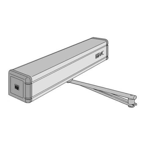
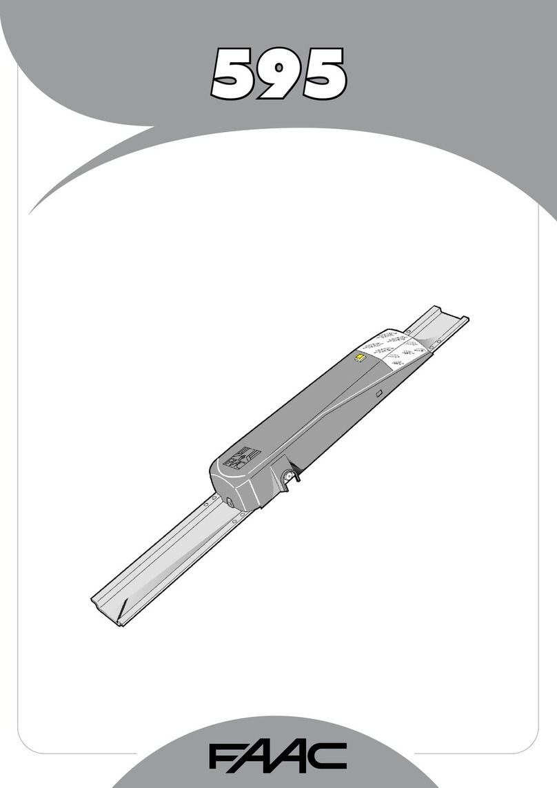
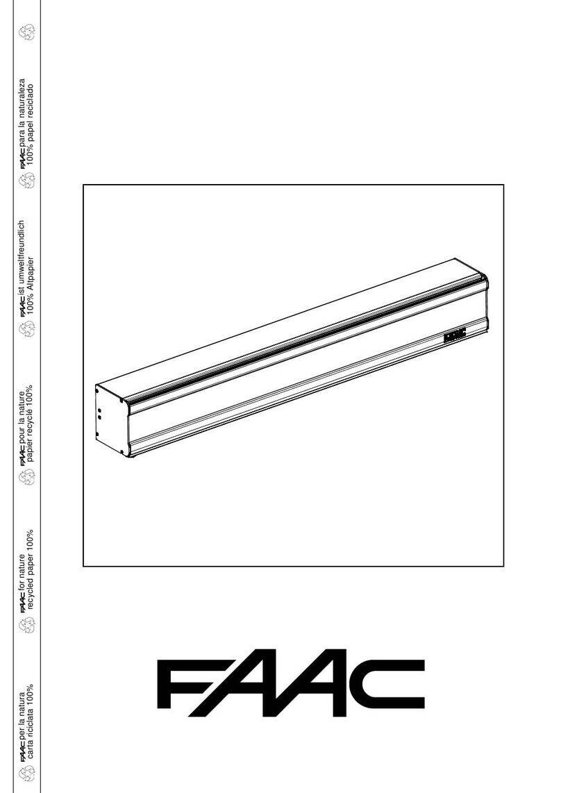
The 950 BM is an electro-mechanical automated system for swing-leaf
doors with direct current motor and return spring. It has an integrated
microprocessorcontrolunitwithself-diagnosisandcontinuousveri-
cation of all door functions and an anti-crushing safety device active
for both opening and closing.
The activation arms is in stainless steel, and it can be pushing or sliding .
The 950 BM is able to do a self-learning procedure of the open and
close positions and automatically measures the door weight for optimal
operation. An optional “closing stroke” function ensures that the door
stays closed even under strong wind. It also has an optional “push
and go” function and in case of power failure the door can be opened
manually then closed with the help of the spring
1. DESCRIPTION AND TECHNICAL CHARACTERISTICS
1.1. APPLICATION LIMITS
Important: To ensure correct application of the FAAC 950 BM unit the
weight of the door must not exceed the value given in Table 3 referred
to its length. The maximum length of the leaf is 55”.
The values of maximum weight vary according to the driving arm used.
For each driving arm there is also a different maximum value for the
depth of the jamb (Table 4) beyond which it is not possible to install
the system correctly.
Pushing
articulated
arm
Sliding
arm
0 - 9 3/4 0 - 6 1/4
inch
1234
5
6
7
8
9
10
11
12
13
Power supply 115 Vac (+6 -10%) - 60 Hz
Absorbed power 100 W
Absorbed current 1 A
Electric motor 24 Vdc with encoder
Dimensions 20 3/4 x 4 1/8 x 4 3/4 “ (length x height x depth)
Weight 22 lbs
Operating ambient temperature -4 to 131 °F
Protection class IP 23 (internal use only)
Dimensions and leaf max weight see Table 3 (paragraph 1.1)
Use frequency continuous
Operation in event of power failure Manual push/pull opening
Conguration of driving arms •pushingarticulatedarm
(version for jamb depth 0 - 9 3/4” )
•slidingarm(armlength17”)
Anti-crushing device standard
Opening angle see table 5-6
Opening speed 4 to 10 s (adjustable)
Closing speed 4 to 10 s (adjustable)
Power supply 115 Vac (+6 -10%) - 60 Hz
Accessories power supply 24 Vdc / 500mA max
Electric lock power supply (N.O./N.C.) 24 Vdc / 500mA max
Standard operating functions (selector switch) Open / Automatic
Manual (Night)
Adjustable functions (trimmer) Opening speed - Closing speed
Pause time
Selectable functions (microswitches) Closing stroke
Standard/slide initialisation procedure
Push and Go - Function selector switch (pos.”2”)
STOP safety device operation - RS232 port
Terminal block outputs Malfunction alarm signal
Electric lock power supply (N.O./N.C)
24 Vdc accessories power supply - Door status signal
Changeover relay controlled by Card Reader
“Two-leaf door” signal - “Interlock” Signal
Terminal block inputs Internal / External Commands
Emergency Command - Key Command
Card Reader Command - Fire-alarm Command
STOP Safety device - Closing Safety device
Rapid connectors KP-CONTROLLER (optional)
Minidec Decoder or RP cards connection
Functions selector switch connection
Leaf length
(inches)
Max leaf weight (lbs)
Articulated arm
Max leaf weight (lbs)
Sliding arm
27 1/2 809 -
29 1/2 705 -
31 1/2 619 -
33 1/2 548 428
35 1/2 489 381
37 1/2 438 342
39 1/2 396 309
41 359 280
43 328 256
45 299 234
47 275 214
49 254 198
51 236 183
53 218 170
55 203 157
Table 3: Application limits of 950 BM operator
Table 4: Max jamb depth
Table 1: Technical specications of 950 BM Operator
Table 2: Technical specications of Control Board 950 I/O
and Control Board 950 MPS
(800) 878-7829
www.FastGateOpeners.com

7
FAAC MODEL 950 BM Door Operator
1.2 DOOR MAX OPENING ANGLE
According to the type of mounting and following the installation dimen-
sions shown in Tables A or B, different door max. opening angles can
be obtained according to the lintel thickness. Table 5 and 6 shows
the maximum values of the opening angles that can be obtained in
thedifferentcongurations.
Tab.5: Door max opening angle with pushing articulated arm
Type of installation Jamb depth (mm) Max opening angle
operator on lintel 0 100°
operator on lintel 125 110°
operator on lintel 250 125°
Tab.6: Door max opening angle with sliding arm
Jamb depth (mm) Max opening angle
0 90°
160 105°
1950 BM operator
2 Microwave radar / Passive infrared sensor
3 T20E outdoor key-operated selector switch
(KEY command)
4 Emergency Closing/Opening pushbutton
5 KP-CONTROLLER programming unit (optional)
6 KP-CONTROLLER inhibition switch (optional)
7 24 Vdc electric lock
8 Junction box
Notes: 1)Tolayelectriccables,usesuitablerigidand/orexiblepiping.
2) Always keep the low voltage accessory connection cables
separate from the 115 V power cables. To avoid interference,
use separate sheaths.
3. INSTALLATION
3.1. PRELIMINARY CHECKS
To ensure correct operation of the automated system the structure of
the existing door must meet the following requirements:
- lengthandweightasspeciedinTable3(paragraph1.1.);
- max.jambdepthasspeciedinTable4;
- robustandrigidstructureoftheleaf;
- goodconditionoftheexistinghinges;
- smooth, uniform movement of the leaf with no abnormal friction
duringitsentiretravel;
- “neutral” position of the door during its entire travel. If the door tends
to close or open, check the alignment of the hinges.
- Presence of mechanical travel stops.
3.2. MOUNTING THE OPERATOR
1) For details on the mounting position of the operator and the type
of arm to use (pushing or sliding), refer to the relevant mounting
table and drill the holes required to mount the operator and the
arm.
NOTE:Thetwointermediateoperatorxingholesarenotinacentral
position (see Mounting tables). The holes are offset in order to ensure
that the operator is mounted with the correct direction of rotation of
the mechanism.
The mounting tables are the following:
Table A: LINTEL MOUNTING (PUSHING ARTICULATED ARM):
Outward opening.
Table B: LINTEL MOUNTING (SLIDING ARM):
Inward opening.
2) Mountthecasingxingbracketsasshowning.3accordingto
thetypeofmountingtobemade.Tightenthescrews(g.3-ref.1)
andtthescrews(g.3-ref2)withouttighteningthemcompletely.
3) Mount the operator using the six M6 screws and washers provided.
Warning:
- The structure of the lintel (or the door) at the operator mounting
positionmustnotexhibitanysignicantdeformation.
- Theoperatormustbemountedparalleltotheoor.
NOTE: If the sliding arm is to be used, the driving arm must be mounted
beforetheoperatorisxedonthelintel(seeparagraph3.3.2.).
3.3. MOUNTING THE DRIVING ARMS
3.3.1. MOUNTING THE PUSHING ARTICULATED ARM (g.5)
1) Close the door.
2) Freearms(1)and(2)bylooseningthexingdowel(3)asshown
ing.5.
3) Fit arm (1) on the coupling of the operator transmission shaft by
meansofthestandardshaft(8)andthescrew(4)provided(g.5).
The arm must be mounted perpendicular to the closed door.
Note: If a greater distance between the operator and the arm is requi-
red, use the shaft modular extensions, available as accessories, until
the required distance is reached. (see Table A/B).
4) Mount plate (5) of arm (2) on the door or the lintel using the two
M6 screws and the washers provided (g. 5). The installation
dimensions are given in Table A/B.
5) Slacken the xing screw (6) and assemble the two arms by
tighteningthedowel(3)(g.5).
6) Turn arm (1) until arm (2) is perpendicular to the closed door or
thelintelasshowning.5(a-b),slidingthespacer(7)alongarm
(2).
7) Tightenthexingscrew(6)betweenthetwoarms.
The length of arm (2) is given in the relevant mounting tables. If
necessary, cut off the section of the arm extending beyond the
articulationandthencoveritsendusingthecapprovided(g.5).
8) Check manually that the door is free to open and close fully and
that it comes to rest against the mechanical stops. If the door
does not close correctly, adjust the return spring as described in
paragraph 9.
Important: The two driving arms must never touch.
NOTE: it is advisable to always adjust the operator internal mechanical
stops(g.1-ref4),open/closed,sothattheyarereachedatthesame
time when the leaf mechanical stops are reached.
3.3.2. MOUNTING THE SLIDING ARM (g.6)
1) Mount arm (1) on the operator transmission shaft by means of
thestandardshaft(5)andthescrew(2)provided(g.6).The arm
mustbettedpointing45°outwardsasshowning.6(a).
Note: If a larger distance is required between the operator and the
arm use the shaft modular extensions available as accessories, until
the required distance is reached (see Table C/D).
Warning:Mountarm(1)onthetransmissionshaftbeforettingthe
operatoronthelintel(g.6).
2) Inserttheteonslide(3)insidetheslidingguide(4)(g.6).
3) Pullarm(1)inwardsmanuallyasshowning.6(b)andsecure
the sliding guide (4) by means of two M6 screws on the closed
door as shown in Table C/D.
4) Check manually that the door is free to open and close fully and
comes to rest against the mechanical travel stops. If the door
does not close correctly, adjust the return spring as described in
paragraph 9.
2. ELECTRICAL SETUP (g. 2a Standard system)
(800) 878-7829
www.FastGateOpeners.com

8
FAAC MODEL 950 BM Door Operator
4. START-UP
1) Make the electrical connections to the 950 I/O electronic control
unit as described in paragraph 6, and connect the mains power
supplytothespecicterminal(g.1-ref.10)ensuringtocrimpthe
earthwiretothelug(g.1-ref.12)screwedtothesupportprole
(g.1-ref.2).Thentightentheterminal(g.1-ref.13)
To gain access to the control unit, pass the cables through the
specialconduit(g.1-ref.1)orbreaktheknockoutareasonthe
casingsides(g.4-ref.6).
IMPORTANT: When mounting the sliding arm or for opening angles
greater than 90°, turn microswitch no. 2 to ON before connecting
power to the system.
2) Close the door.
3) Power up the operator.
4) Check that the green LEDs LD1 and LD3 on the board 950MPS
light up.
5) Check that the status signalling LEDs on the board 950I/O are
in the default status shown in Table 7 .
NOTE: The default status of the LEDs with the door closed at rest is
shown in bold type.
Table 7: Operation of the status signalling LEDs for 950 I/O board
LED ON OFF
LD1 Accessories power present Accessories power absent
LD2 Card Reader active Card Reader inactive
LD3 Internal sensor active Internal sensor inactive
LD4 External sensor active External sensor inactive
LD5 Emergency inactive Emergency active
LD6 STOP safety device inactive STOP safety device active
LD7 CL safety device inactive CL safety device active
LD8 Key active Key inactive
LD9 Fire-alarm active Fire-alarm active
6) Run a SET-UP cycle as indicated in paragraph 4.1.
4.1. SET UP PROCESS
Once the system is powered up, hold down SW1 button for at least
5 sec., until the LD2 red LED on the 950MPS board lights up. The
LEDwillstartashingtoindicatethatSETUPprocessisinprogress.
During this process the following parameters are set:
- measuringthemassofthedoor;
- determiningthetravelstoppositions;
The door opens at low speed, then closes half way before switching
back to opening.
Subsequent closure is performed by the return spring.
The process may be inhibited in any of the following conditions:
- function selector switch in the 2 (MANUAL/NIGHT) position or KP-
CONTROLLER programming unit in MANUAL or NIGHT position.
- incorrect connection of the accessories (electric lock, control/safety
devices);
- incorrect positioning of the programming unit microswitches.
NOTE: To repeat the initialisation procedure hold down the SW1 button
for more than 5 seconds.
Check that door opens and closes correctly by sending an opening
command to one of the following inputs: Internal Sensor, External
Sensor or Key command. Set the trimmers (par.5.2) and program the
microswitches (par.5.4) according requirements.
5. 950 MPS ELECTRONIC CONTROL UNIT (Fig. 8)
5.1 SETTING THE TRIMMERS
Theprogramming unitfeatures trimmers(g.8) which regulate the
following parameters:
Trimmer TR1 to set the opening speed.
Setting from 4 to 10 seconds.
Trimmer TR2 to set the closing speed.
Setting from 4 to 10 seconds.
Trimmer TR3 to set the pause time (AUTOMATIC logic).
Setting from 0 to 30 seconds.
5.2 SIGNALLING LEDs
LD1 Led = Green LED - electric motor power supply.
LD2 Led = Red LED - indicates SET-UP/Alarm.
LD3 Led = Green LED - 5V power supply.
950MPS ELECTRONIC CONTROL UNIT LAYOUT AND DESCRIPTION
MICROSWITCHES RS-232 CONNECTOR
ADJUSTING TRIMMER SIGNALLING LED
MOTOR CONNEC-
TOR
40VDC CONNEC-
TOR
Fig. 8
(800) 878-7829
www.FastGateOpeners.com

9
FAAC MODEL 950 BM Door Operator
5.4. PROGRAMMING THE MICROSWITCHES (g.9)
The 950BM has two series of microswitches, one on the 950MPS board
and one on the 950 I/O board.
The system is supplied with all the microswitches in the OFF position.
5.4.3. MICROSWITCH No. 3 - SELECTOR FUNCTION
This function allows the operating function to be selected with the
selector switch in the “2” position.
OFF = MANUAL Function
ON = NIGHT Function
5.4.4. MICROSWITCH No. 4 - PUSH AND GO
When activated, this function enables the opening command to be
givenbypushingthecloseddoormanually.Itissufcienttogivethe
door an initial push/pull in the opening direction.
OFF = Function DISABLED
ON = Function ENABLED
WARNING: It is advisable not to enable this function if the door is
subject to strong wind, according to its structure and dimensions, as this
could activate the system’s spontaneous opening or motion reversing.
5.4.5 . MICROSWITCHES Nos. 5/6//9 - INACTIVE
5.4.6. MICROSWITCH No. 7 - STOP SAFETY DEVICE
It makes it possible to detect activation of the STOP safety device
during the entire door travel (COMPLETE) or to disable detection
beyond 70° opening (REDUCED).
OFF = COMPLETE Function
ON = REDUCED Function
WhentheSTOPsafetycontrolisensuredbyanactivesensortted
on the leaf, if you enable the REDUCED function, the detection of any
obstacle (e.g. side wall) is prevented which would cause interruption
of the work cycle.
5.4.6. MICROSWITCH No. 8 - SCP Function
SCP Function (Selectable Close Power)
If the SCP function is enabled, the door can be closed even if
there is friction due to rigid seals or electric locks with a particularly
difcultconnection.WhentheSCPfunctionisoperating,theelectronic
anti-crush facility is still active, but is less sensitive. For reasons of safety,
we therefore advise you to use the function only in case of real need.
OFF = Function DISABLED
ON = Function ENABLED
6. 950 I/O ELECTRONIC CONTROL UNIT LAYOUT
5.4.1. MICROSWITCH No. 1 - CLOSING STROKE
This function enables the closed position force to be increased by
further loading the transmission system after the door has reached
the mechanical closure stop.
It is advisable to use this function to assist activation of the electric lock.
OFF = Function DISABLED
ON = Function ENABLED
5.4.2. MICROSWITCH No. 2 - SET-UP PROCESS
When mounting the “sliding” arm or for opening angles greater than
90°, this microswitch has to be enabled.
OFF = Function DISABLED
ON = Function ENABLED
MICROSWITCHES
OFF
ON Fig. 9
Fig. 10
N° Function OFF ON
1 Closing stroke Disabled Enabled
2 Setup process Standard Non-standard
3 Outside selector - pos. 2 Manual Night
4Push And Go Disabled Enabled
5 Not in use - -
6 Not in use - -
7 Safety STOP detection Complete Reduced
8 SCP Disabled Enabled
9 Not in use - -
10 RS232 Port Disabled Enabled
Tab. 8: DS1 on the 950MPS board
1 2 3 4 5 6 7 8 9 10
(800) 878-7829
www.FastGateOpeners.com

10
FAAC MODEL 950 BM Door Operator
5.4.7 MICROSWITCH No. 10 - RS232 PORT
It makes it possible to enable the RS232 port connection to PC for
software update. In normal use conditions, the dip switch is in OFF
position.
OFF = Port DISABLED
ON = Port ENABLED
6. 950 I/O ELECTRONIC CONTROL UNIT (Fig. 10)
6.1 LAYOUT AND DESCRIPTION
DS1
N° Function OFF ON
1 Push and Go pause time 2 seconds Automatic
2Opening delay with electric
lock
200ms 500ms
MICROSWITCH No. 1 - Push and go Pause time
Following the opening with the Push & Go function you can choose:
tohavetheautomatedsystemuseaxed2secondspausetime,
or the time used by opening with the pulse generator in automatic
operating mode (see chap. 10.7 - Diagram 3: Setup).
OFF = 2 sec. pause time
ON = Automatic pause time
MICROSWITCH No. 2 - Lock activation delay
If this dip-switch is ON (enabled), the door movement is delayed by
500msec with respect to the electric lock command. If OFF (disabled),
delay is 200 msec.
SW1 SET-UP pushbutton
Hold down the SET-UP button for 5 sec. to start the set-up cycle.
1 FUSE F1 T4A 125 Vac. - 5x20 (UL/CSA)
2 J1 CONNECTORTransformerSecondarywinding-g.10
3 J2 CONNECTOR Rapid Connector of Manual/Night, Open,
Automatic function selector switch
4 J3 CONNECTOR KP-Controller Connection
1- 2 Connector of KP-Controller programming unit (optional) as
showning.24.
Use a 2 x 0.5 mm² shielded cable (“bus” communication) for the
connection.Respecttheconnectionpolarityasshowningure
24.
Important: The maximum permissible length of the connection
cable is 150’.
To inhibit operation of the SD-KEEPER, make the jumper between
terminalsoftheLOCKswitch(g.24).
5 J4 TERMINAL BLOCKInputsConnection(gs.11,12,16)
7- 8 GND
Accessories power supply Negative and contacts Common
9 +24Vdc
+24Vdc accessories power supply
10 Internal Command - N.O. Contact
Any pulse generator (pushbutton, sensor, etc.) which, by closing
a contact, commands door opening.
To install several pulse generators as Internal Command, connect
the N.O. contacts in parallel.
11 External Command - N.O. Contact
Any pulse generator (pushbutton, sensor, etc.) which, by closing
a contact, commands door opening.
To install several pulse generators as External Command, connect
the N.O. contacts in parallel.
12 Emergency Command - N.C. Contact
Any pulse generator (normally a pushbutton) which, by opening
a contact, commands an emergency closure of the system.
Alternatively this input can be used to command emergency
opening by programming the system in a suitable manner using
the KP-CONTROLLER programming unit (optional).
To install several emergency command devices, connect the N.C.
contacts in series.
NOTE: If emergency command devices are not connected, jumper
inputs 7 and 12.
Attention: Using the KP-CONTROLLER programming unit, you
can change the type of contact from N.C. to N.O.
13 CLOSE Safety Command - N.C. Contact
Any device (safety sensor, photocell, etc.) which, by opening a
contact, has a safety effect on the closing movement of the door.
The safety device causes an immediate reversing of the closing
movement of the door, but has no effect on the opening movement
of the door.
To install several CLOSE safety devices, connect the N.C. contacts
in series.
N.B.: If the CLOSE safety devices are not installed, jumper inputs
7 and 14.
7 8 9 10 11 12 13 14 15 16 17 18 19
GND
GND
+ 24 Vdc
Internal Command
External Command
Closure Safety Command
STOP Safety Command
Emergency Command
Key Command
Fire-alarm Command
Card Reader Command
GND
GND
J4
Fig. 11
7 8 9 13 14 15
TX RX
PB SENSOR
+
-
C
+
+
-
-
C
J4
Fig. 12
7 8 9 10 11 12 13 14 15 16 17 18 19
(800) 878-7829
www.FastGateOpeners.com

11
FAAC MODEL 950 BM Door Operator
14 STOP Safety Command - N.C. Contact
Any device (safety sensor, photocell, etc.) which, by opening a
contact, has a safety effect on the operating cycle. In particular,
this safety device interrupts the opening/closing movement of the
door.
When the safety device is disengaged, the door resumes its
opening/closing movement and continues to the end of the cycle.
To install several STOP safety devices, connect the N.C. contacts
in series.
N.B.: If STOP safety devices are not installed, jumper inputs 7
and 13.
15 KEY Command - N.O. Contact
Any pulse generator (pushbutton, sensor, etc.) which, by closing
a contact, commands door opening.
To install several pulse generators as Internal Command, connect
the N.O. contacts in parallel.
16 FIRE-ALARM Command - N.O. Contact
Anydevice(re-alarmsensor,etc.)which,byclosingacontact,
commands door closing.
Permanence of the closed contact, inhibits operation of any other
pulse generator.
To install several devices as FIRE-ALARM Command, connect
the N.O. contacts in parallel.
17 CARD READER Command - N.O. Contact
Any device (card reader, digital buttonboards, etc.) which, by giving
a 24Vdc pulse, commands the door opening and the activation
of the changeover relay (terminals 20/21/22, J6 terminal board).
Theopenpausetimeisxedat10sec.
18 - 19 GND
Accessories power supply Negative and contacts Common
7 8 9 10
1 2 3 4 5 6J5 J4
max 0.5A/24Vdc
1 2 3 4 5 6 7 8 9 10
J5 J4
max 0.5A/24Vdc
1 2 3 4 5 6
DOOR
OPEN
DOOR
CLOSED
COM.
max 0.5 A/24 Vdc
15 16 17 18 19
CARD READER - 24Vdc Signal
C. R. Comand
GND
+ -
22 23 24 25 26
max 0.5 A/24 Vdc
ALARM Output
ALARM Output
+24 Vdc
GND
Fig. 13 Fig. 14
Fig. 15 Fig. 16
Fig. 17 Fig. 18 Fig. 19
J4
J5
J6 J6
J6 25 26 27 28
Interlock Signal
2 Leaf Signal
20 21 22
Com. changeover Relay
N.O.
changeover Relay
N.C.
changeover Relay
(800) 878-7829
www.FastGateOpeners.com

12
FAAC MODEL 950 BM Door Operator
6 J5 TERMINAL BLOCK Connectionto relayOutputs (gs.
13,14, 15)
1 Electric lock - Common
2 Electric lock - N.O. Contact (max. capacity 0.5 A/24 V)(g.13).
If no power is supplied the electric lock is active and therefore
guarantees closing mechanical locking.
In the NIGHT function the electric lock is active even if no power
is supplied. In the event of an opening command (Key or EMER-
GENCY command), the electric lock is temporarily powered to
enable the door to be opened. In this case a reverse stroke
command is also given to enable the mechanical release of the
system.
3 Electric lock - N.C. contact (max. capacity 0.5 A/24 V)(g.14).
The output is suitable for commanding a magnetic closure system.
If no power is supplied, the electric lock is not active. In the NIGHT
function the electric lock is powered and hence active. In the event
of an opening command (internal command or EMERGENCY
OPENING), the power supply to the electric lock is temporarily
cut off to allow the door to be opened.
4 Door status CLOSED - N.O. contact (max. capacity 0.5 A/24
V).
When the door CLOSED position is reached, the contact closes.
5 Door status - Common
6 Door status OPEN - N.O. contact (max. capacity 0.5 A/24 V).
When the door OPEN position is reached, the contact closes.
7 J6 TERMINAL BLOCK Relay outputs and special functions
(gs.17,18,19)
20 Changeover relay - Common
21 Changeover relay - N.O. Contact
This output is activated (N.C.) by the Card Reader input for 2 sec.
Attention: this output is not suitable for controlling electric locks.
22 Changeover relay - N.C. Contact
This output is activated (N.O.) by the Card Reader input for 2 sec.
Attention: this output is not suitable for controlling electric locks.
23 Alarm Output - Common
24 Alarm Output - N.O. Contact
This output is activated (N.C.) if an alarm is present. At the same
time LED2 on the 950 I/O board lights up to indicate the alarm
condition.
25 +24Vdc
+24Vdc accessories power supply
8. FUNCTION SELECTOR SWITCH
The950BMoperatorhasa3-positionfunctionselectorswitch(0-1-2)mountedononesideofthecover(g.4-ref.2).Theselectorswitch
positionisxed:however,dependingonthetypeofinstallation(ondoorpostoronlintel),theconnectioncabletothe950I/Ounitmustbe
positionedasshownings.4a/b.Theselectorswitchcanbeeasilyinspectedbyopeningtheprotectiondoor(g.4-ref.1).
Theselectableoperatingfunctionsareshowning.20.
1
0
2
POSITION “1”: OPEN
When this function is selected, the door opens and remains open.
POSITION “0”: AUTOMATIC
If this function is selected, when an internal/external command is given, the door opens and then re-
closes after the pause time.
POSITION “2”: MANUAL/NIGHT
The position “2” can be used to select two different operating functions according to the programming
carried out on the 950 MPS programming unit (see paragraph 5.4.3). The two functions are:
MANUAL: The door can be opened manually.
NIGHT: The external command is inactive. The door can be opened solely by activating the Key com-
mand(g.11).
7. INSTALLING THE COVER
Please refer to Fig. 4 for the cover assembly instructions. The
parts are:
1 Side cover support (2 included)
2 Side cover support screws (4 included - 2 per side)
3 Side cover (2 included)
4 Side selector cover screws (4 included - 2 per side)
5 Selector cover (2 included)
6 Selector switch
7 Aluminum cover
8 Cover screws (2 included)
For best results assemble the parts following the above order 1
thru 8.
26 GND
Accessories power supply Negative and contacts Common
27 “Interlock”output
This terminal is used to enable communication between two 950BM
automatedsystemsprogrammedin“Interlock”conguration,see
par. 11.1.
28 “2 Leaves” output
This terminal is used to enable communication between two 950BM
automatedsystemsprogrammedin“2Leaves”conguration,see
par. 11.2.
8 J7 ConnectorQuick-tconnectorforconnectingRPplug-in
ReceiversorMinidec/Decoderdecodingcards(g.10).
9 J9 TERMINAL BLOCKNOT-AUS(g.10)
N.C. contact for emergency stop. If there is no connection between
the two terminals, the automated system is locked and cannot
perform any electrical movement.
10 J10 ConnectorQuick-tconnectorfor40Vdcpowersupplyto
950MPSboard(g.10)
11 J11 Connector Quick-tconnectorfordoorstatussignalsto
950MPS(g.10)
Fig. 20
(800) 878-7829
www.FastGateOpeners.com

13
FAAC MODEL 950 BM Door Operator
9. ADJUSTING THE SPRING
9.1. SPRING PRELOADING
If the door movement is not uniform (e.g.: door not closing comple-
tely or closing with too much force) proceed as follows to adjust the
spring preloading:
1) Cut power to the automated system and release from the door
thearmsecureddirectlyonthetransmissionshaft;
2) Rotatethearmuntilthestop-pointscrew(g.21ref.4)isinline
withtheinspectionslot(g.21ref.3);
3) Removethescrew,whilekeepingthearminposition;
4) To increase preloading: rotate the arm in opening direction until
thenextxingpositionofthestop-pointscrew(g.21ref.5)isin
linewiththeinspectionslotandxthescrewagain.
To reduce preloading: rotate the arm in closing direction until
thenextxingpositionofthestop-pointscrew(g.21ref.5)isin
linewiththeinspectionslotandxthescrewagain.
5) Reinstallthearmcorrectly(seepar.3.3.);
6) Run a new SETUP cycle.
9.2. CHECKING SPRING EFFICIENCY
Weadviseyoutoperiodicallychecktheefciencyofthespring-
this is the procedure:
1) SelecttheManualfunction;
2) Removetheprotectivedeviceofthedrivesystem(seeg.1ref.
6);
1) Withthedoorclosed,traceaverticallineonthespring(g.22
ref.1);
2) Openthedoorcompletely;
3) Check the line you had traced.
Ifthedistortionisnotuniformalongthewholespringheight(g.
22ref.2),butisirregular(g.22ref.3),lubricatethespring
withspecicslidinggrease.
Fig. 22
a b c
1
2
3
1 Closing limit-switch
2 Opening limit-switch
3 Slot for inspection of stop-point screw
4 Stop-point screw
5 Fixing positions of stop-point screw
5
5
5
4
Fig.21
(800) 878-7829
www.FastGateOpeners.com

14
FAAC MODEL 950 BM Door Operator
10. KP-CONTROLLER PROGRAMMING UNIT
The KP-Controller is used for selecting operational functions, as
well as adjusting and programming the 950 Series automatic doors.
Itisdividedintotwoparts:axedpartusedforsignallingof
operational functions by means of pushbuttons and relevant
signalling LEDs (Fig. 23 ref.A), and a removable part with LCD
display and selection buttons to access complete programming
(Fig. 23 ref.B).
The KP-Controller display can be used as a temporary
programming unit if the parameter “Keep settings” in the
ADVANCED MENU is set to ON: after all programming and
adjustments have been carried out, KP-Controller can be fully
removed because the settings remain stored on the 950MPS
control board.
If KP-Controller is installed without display, a cover is provided (Fig.
23 ref.C).
KP-Controller can be disabled by a combination of keys (see the
special LOCK function) or by internally installing a jumper that acts
as a switch (Fig. 24 ref. LOCK).
10.1. MOUNTING
RefertoFig.24foranexplodedviewofmounting;twoknockout
areas marked A and B are provided for entry of connection cable.
10.2 . CONNECTIONS
Connect the KP-Controller to the 950 I/O control board by a
2x0.5mm² max 50m cable (Fig. 24).
If the two LOCK terminals are connected to each other as shown in
Fig.24, all keys on the programmer are disabled.
10.3 . DIAGNOSTICS
The KP-Controller (also without display) has a diagnostic function
which, in case of an alarm, interrupts the normal display of the fun-
ction every 2 seconds in order to show the fault status for 1 second
byacombinationofashingLEDs.
Consult Fig. 25 and table 9 to identify the type of alarm according
totheashingLEDs.Intheeventofseveralsimultaneousfaults,
thecodeoffaultdetectedrstisdisplayed.
2x0.5 mm2
max 50m
Fig. 24
A
B
Fig. 23
A
B
C
Table 9 DIAGNOSTICS Led =on = off
DESCRIPTION MEANING
3 FORCED OPEN Door forced opening in progress
7 EMERG. ON Emergency input active
9 OBST.INCLOS. Closingobstacledetected3successivetimes;Resetnecessarytorestoreoperation
10 v Lock locked in closed position
12 v Incorrect power supply to accessories (24Vdc absent)
15 v Setup not possibile
18 v Initialisation process not possible on motor: leaf stroke too long
20 v Initialisationprocessnotpossibleonmotor:insufcientleafstroke
22 v Leaf too heavy
24 v Motor failure
26 v 950 MPS control board failure
27 v No power supply
28 v Setup cycle required
29 v Encoder failure
30 v Driver motor failure
31 v EEPROM failure
32 v Master/Slave communication error
12 3 4 5 876
1
2
3
4
5
678
Fig. 25
(800) 878-7829
www.FastGateOpeners.com

15
FAAC MODEL 950 BM Door Operator
10.4 . OPERATIONAL FUNCTIONS
Selectionisperformedbypressingthekeysonthexedpartofthe
programmer - the function is indicated by the corresponding LED
lighting up.
Note: when the “Night” or “Manual” modes have been set, the rele-
vant selection keys must be pressed to exit the modes.
MANUAL
The door is free and can be activated manually.
BI-DIRECTIONAL
Pedestriantransitispossibleinbothdirections;theinsideand
outside radars are enabled.
ONE-WAY
Pedestriantransitispossibleinonedirectiononly;theexternal
radar is disabled.
PARTIAL OPENING
The door opens only partially (standard: 80%)
Partial opening can be adjusted in range from 60% to 90% of total.
TOTAL OPENING
The door opens completely.
AUTOMATIC
The door opens (partially or totally) and then re-closes after the set
pause time (standard: 2 sec.).
Pause time adjustment: form 0 to 30 sec.
DOOR OPEN
The door opens and stays open.
NIGHT
The door closes and the lock (if present) is activated. The internal
and external radars are disabled.
The Key command causes opening and closing after the night
pause time elapses (standard: 7 sec).
Adjusting range of night pause time: from 0 to 30 sec.
To obtain partial opening in this mode, before selecting the “Night”
function, activate the “Partial Opening” function.
10.5 . SPECIAL FUNCTIONS
SETUP
Setup is the door initialisation function during which parameters are
self-learned.
To activate, simultaneously press keys 1and 5for 5 sec.
RESET
Reset is the function for restoring normal operating conditions after
some types of alarm have been signalled.
To activate, simultaneously press keys 2 and 3.
LOCK
When active, the Lock function disables the KP-Controller.
To activate and de-activate, simultaneously press keys 3and 4for
5 sec.
10.6 . INSERTING AND CHANGING BATTERY
To keep the clock inside KP-Controller active even in the event
of a power failure, a 3V model CR1216 lithium battery has to be
installed.Toinsertorreplacethebattery,ndthecompartmenton
the printed circuit (Fig. 27) and follow the indicated polarity.
Fig. 27
Fig. 26
MANUAL
BI-DIRECTIONAL
ONE-WAY
PARTIAL OPENING
TOTAL OPENING
AUTOMATIC
DOOR OPEN
NIGHT
1
2
3
4
5
1
2 3 4
5
(800) 878-7829
www.FastGateOpeners.com

16
FAAC MODEL 950 BM Door Operator
10.7. PROGRAMMING
To access programming while the standard view is shown on the
display, press any of keys ^, vor OK.
Programming is subdivided into main menus (see Chart 1) split into
subjects.
After selecting the menu with keys ^or v to access it press OK.
Each menu is, in turn, subdivided into sub-menus at different para-
meter setting levels.
Use keys ^or v toselect(sub-menuorparameter)andconrm
with the OK key.
An asterisk on the display indicates the currently active setting.
To exit programming, select the “exit” function at each level. Other-
wise, after about 2 minutes, the display automatically returns to
standard view.
Thefollowingow-chartsandnotesshowthevariousprogramming
menus and options.
Diagram 2: Language selection
Diagram 1: Programming
DAY HOUR
VER DATE
SETUP
TIMER
LANGUAGE
TIMER
PROGRAMMING
CLOCK
ADVANCED MENU
DIAGNOSTICS
LOCK
ITALIANO
ENGLISH
DEUTSCH
FRANCAIS
ESPANOL
LANGUAGE
(800) 878-7829
www.FastGateOpeners.com

17
FAAC MODEL 950 BM Door Operator
Diagram 3: Setup
Diagram 4: Lock
SETUP 80%
7 SEC.
*
*
2 SEC. *
CLOSING:
STANDARD
NO STANDARD
*
OBSTACLE
DETECTION
NIGHT PAUSE
TIME
PARTIAL
OPENING
PAUSE TIME
EXIT
LOCK
OFF
ON *
*
ALWAYS
ONE WAY+NIGHT
NIGHT
KIT
LOCK
EXIT
(800) 878-7829
www.FastGateOpeners.com

18
FAAC MODEL 950 BM Door Operator
Diagram 5: Diagnostics
Diagram 6: Operation parameters
RESET
950 v.
DIAGNOSTICS NR. CYCLE
XXXX
ALARM N.
(alarm description)
PASSWORD
0000
PASSWORD
0000
PASSWORD
0000
PASSWORD
0000
KEEP
SETTINGS
OFF
ON
8
8
EXIT
*
*
*
ADVANCED MENU
OPERATION
PARAMETERS CLOSING SPEED
OPENING SPEED
correct code
incorrect code
IN/OUT SETUP
VARIOUS
EXIT
CHANGE
PASSWORD
(800) 878-7829
www.FastGateOpeners.com

19
FAAC MODEL 950 BM Door Operator
Diagram 7: In/Out Setup
PASSWORD
0000
PASSWORD
0000
PASSWORD
0000
PASSWORD
0000
IN/OUT SETUP EMERG OPEN
CLOSE
OUT OP/CL NO
OUT ALARM NO
NC
USCITA
*
*
NC
NO
NC
*
*
ADVANCED MENU
OPERATION
PARAMETERS
VARIOUS
EXIT
CHANGE
PASSWORD
correct code
incorrect code
(800) 878-7829
www.FastGateOpeners.com

20
FAAC MODEL 950 BM Door Operator
codice errato
codice corretto
Diagram 8: Various - Change passwod - Test prog
PASSWORD
0000
PASSWORD
0000
PASSWORD
0000
PASSWORD
0000
IN/OUT SETUP
STAND SETUP STANDARD
NO STANDARD
INTERLOCK
MASTER
SLAVE
NO MEMORY
WITH MEMORY
EXIT
NEW PASSWORD
0000
NEW PASSWORD
0000
NEW PASSWORD
0000
NEW PASSWORD
0000
*
*
MASTER
SLAVE
ON
OFF *
ON
OFF *
2 LEAVES
*
TEST PROG
ON
OFF *
ADVANCED MENU
OPERATION
PARAMETERS
VARIOUS
EXIT
CHANGE
PASSWORD
correct code
incorrect code
restores
standard
parameters
(800) 878-7829
www.FastGateOpeners.com
Other manuals for 950 BM
1
Table of contents
Other FAAC Door Opening System manuals
Popular Door Opening System manuals by other brands

Sesamo
Sesamo PROSWING operating instructions

Bohle
Bohle Santos instruction manual

Dormakaba
Dormakaba G-SR EMR Series Fixing instructions

Tormax
Tormax iMotion 1301.FIRE Instructions for use

Hailo
Hailo HFO Instructions for assembly and use

Assa Abloy
Assa Abloy Corbin Russwin PED5200 installation instructions