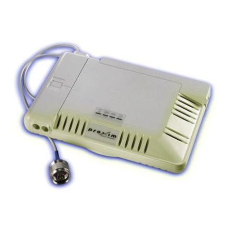
Proxim MP11 5012-SUI User manual

Quick Install Guide
Tsunami MP.11 5012-SUI and 5054-SUI
Version 4.0.0
Part Number 73883 (Print version)
Part Number 73881 (CD version)

Page 2 Copyright © 2007 Proxim Wireless
NOTICES
Copyright
Copyright ©2007 Proxim Wireless Corporation, San Jose, CA. All rights
reserved. Covered by one or more of the following U.S. patents: 5,231,634;
5,875,179; 6,006,090; 5,809,060; 6,075,812; 5,077,753. This manual and
the software described herein are copyrighted with all rights reserved. No
part of this publication may be reproduced, transmitted, transcribed, stored in
a retrieval system, or translated into any language in any form by any means
without the written permission of Proxim Wireless Corporation.
Trademarks
Tsunami, Proxim, and the Proxim logo are trademarks of Proxim Wireless
Corporation. All other trademarks mentioned herein are the property of their
respective owners.

All rights reserved Page 3
CONTENTS
INTRODUCTION.................................................................. 4
Key Features.................................................................................................... 4
PACKAGE CONTENTS ....................................................... 5
HARDWARE AND SOFTWARE INSTALLATION ............... 7
Step 1: Choose a Location............................................................................... 8
Step 2: Unpack Shipping Box ......................................................................... 9
Step 3: Attach Cables..................................................................................... 10
Step 4: Install the Security Cover (Optional) .................................................. 12
Step 5: Mount the Unit ................................................................................... 13
Step 6: Power On the Unit ............................................................................. 15
Step 7: View LEDs ........................................................................................ 15
Step 8: Connect the Pigtail Cable .................................................................. 17
Step 9: Align the Antenna............................................................................... 19
Step 10: Install Documentation and Software ................................................ 20
INITIALIZATION................................................................. 21
Setting the IP Address.................................................................................... 21
Accessing the Web Browser ......................................................................... 22
Accessing the Command Line Interface ....................................................... 22
BASIC CONFIGURATION ................................................. 23
System Conguration..................................................................................... 23
Dynamic Frequency Selection (DFS)............................................................. 23
Transmit Power Control.................................................................................. 23
IP Conguration ............................................................................................. 24
Interface Conguration................................................................................... 24
VLAN Conguration ....................................................................................... 24
Security Settings ............................................................................................ 25
Upgrading Embedded software...................................................................... 25
Applying Changes .......................................................................................... 25
DEFAULT SETTINGS ........................................................ 26
TECHNICAL SERVICES AND SUPPORT......................... 28
Support Options ............................................................................................. 28

Page 4 Copyright © 2007 Proxim Wireless
INTRODUCTION
The Tsunami MP.11 5012-SUI and 5054-SUI are a exible wireless indoor client
that let you design solutions for point-to-point links and point-to-multipoint
networks. It is the client or satellite side in a wireless link.
The 5012-SUI and 5054-SUI are parts of the Tsunami MP.11 product family,
which is comprised of several additional products, including:
The 5054 Base Station (BSU) and the 5054 Subscriber Unit (SU) for indoor
installation
The 954-R, 2454-R, 4954-R, 5054-R, and 5054-R-LR Base Station and
Subscriber Station Units for outdoor installation
5012-SUR Subscriber Unit for outdoor installation
KEY FEATURES
Some of the key features of the unit are:
The use of a highly optimized protocol for outdoor applications
Routing and bridging capability
Asymmetric bandwidth management
Management through a Web Interface, a Command Line Interface (CLI), or
Simple Network Management Protocol (SNMP)
Software and conguration upgrade through le transfer (TFTP)
VLAN support
This document shows the basics of setting up the 5012/5054-SUI. For detailed
information, see the Installation and Management Guide.
▪
▪
▪
▪
▪
▪
▪
▪
▪

All rights reserved Page 5
PACKAGE CONTENTS
Each 5012/5054-SUI shipment includes the items in the following table. Verify
that you have received all parts of the shipment.
Note:
Unless listed here, cables are not included with the unit.
Tsunami MP.11 5012-SUI or
5054-SUI unit
N-type Male Terminated
Pigtail (for external antenna
connection)
Power Adaptor
Security Cover
Ceiling/Wall Mount Plate
Unit Wall- or Ceiling-
Mounting Hardware
Qty. Description
2 ea Mounting Plug
2 ea. Pan-head Screw
Installation CD and Quick
Installation Guide

Page 6 Copyright © 2007 Proxim Wireless
15 dBi Window Antenna
(included with 5012-SUI-
WA-xx and 5054-SUI-WA-
xx; available for order
separately)
Outdoor Antenna
Mounting Hardware and
Documentation (included
with 5012-SUI-WA-xx and
5054-SUI-WA-xx)
Qty. Description
2 ea. L-Type Mounting Plate (top)
2 ea. L-Type Mounting Plate
(bottom)
6 ea. M5 Screw (with washer)
2 ea. Screw
2 ea. Wall Mounting Plug
1 ea Outdoor Mounting Conguration Flyer
Indoor Antenna
Mounting Hardware and
Documentation (included
with 5012-SUI-WA-xx and
5054-SUI-WA-xx)
Qty. Description
2 ea. Screw
2 ea. Washer
2 ea. Suction Cup/Rotation Bar
1 ea. Indoor Mounting Conguration Flyer

All rights reserved Page 7
HARDWARE AND SOFTWARE INSTALLATION
Note:
Be sure to read the Release Notes as they contains software version and
driver information that may not have been available when this document
was produced.
IMPORTANT!
Before installing this product, see Safety and Regulatory Compliance
Information on the product CD for important information.
IMPORTANT!
Before installing this product, see Safety and Regulatory Compliance
Information on the product CD for important information.
IMPORTANT!
All units must be installed by a suitably trained professional installation
technician or by a qualied installation service.
IMPORTANT!
All units must be installed by a suitably trained professional installation
technician or by a qualied installation service.
WARNING!
For your own safety, when using DC power, use only the power adaptor
supplied with the unit.
WARNING!
For your own safety, when using DC power, use only the power adaptor
supplied with the unit.

Page 8 Copyright © 2007 Proxim Wireless
Step 1: Choose a Location
To make optimal use of the 5012/5054-SUI, you must nd a suitable location
for the hardware. The range of the unit largely depends upon the position of
the antenna. Proxim recommends you do a site survey, observing the following
requirements, before mounting the 5012/5054-SUI hardware.
The location must allow easy disconnection of the unit from the power
outlet if necessary.
The unit must not be covered and the air must be able to ow freely around
the unit.
The unit must be kept away from vibration, excessive heat, and humidity,
and kept free from dust buildup.
The installation must conform to local regulations at all times.
Caution!
Local regulations may require the use of a lightning arrestor at
the building ingress point. Be sure to comply with this and all local
regulations. You can purchase the Proxim Lightning Protector
MP.11/QB.11 (70251); see the documentation that comes with
the Lightning Protector for more information and installation
instructions.
▪
▪
▪
▪

All rights reserved Page 9
Step 2: Unpack Shipping Box
Unpack the unit and accessories from the shipping box.
Note the Ethernet and MAC addresses of the unit, as well as the serial
number. The addresses may be used when conguring the unit. The serial
number is required to obtain support from Proxim. Keep this information in
a safe place.
1.
2.

Page 10 Copyright © 2007 Proxim Wireless
Step 3: Attach Cables
Cabling without Power Over Ethernet (PoE)
Plug the barrel of the power cable from the power supply into the power
jack (the leftmost port in the back of the unit, see gure).
Connect one end of an Ethernet cable (not supplied) to the unit’s LAN
port (see gure). The other end of the cable should not be connected to
another device until after installation is complete:
Use a straight-through Ethernet cable if you intend to connect the
5012/5054-SUI to a switch, hub, or patch panel
Use a cross-over Ethernet cable or adapter if you intend to connect the
5012/5054-SUI to a single computer.
Continue with “Install the Security Cover”.
Cabling without Power Over Ethernet (PoE)
You must use an Active Ethernet adapter such as the ORiNOCO 1-Port
Active Ethernet DC Injector (ordered separately). Connect one end of an
Ethernet cable (not supplied) to the unit’s LAN port. Connect the other end
to the Data and Power Out port of the DC Injector (see gure).
Connect one end of a second Ethernet cable (not supplied) to the Data In
port of the DC Injector (see gure). The other end of the cable should not
be connected to another device until after installation is complete:
Use a straight-through Ethernet cable if you intend to connect the
5012/5054-SUI to a switch, hub, or patch panel.
Use a cross-over Ethernet cable or adapter if you intend to connect the
5012/5054-SUI to a single computer.
1.
2.
º
º
3.
1.
2.
º
º

All rights reserved Page 11
Continue with “Install the Security Cover”.4.

Page 12 Copyright © 2007 Proxim Wireless
Step 4: Install the Security Cover (Optional)
You can optionally install a security cover to deter unauthorized access to the
5012/5054-SUI. The security cover is a plastic enclosure that prevents access
to the cabling and the Reset and Reload buttons.
Open the split end of the security cover just enough to slide the power
cable (if not using PoE) and the Ethernet cable through the opening until
they t inside the straight clamping portion of the cover. Exercise care
as you slide the cable(s) so you do not accidentally break the cover (see
gure).
Slide the hinging end of the security cover into the hole on the rear panel
of the 5012/5054-SUI to the left of the connectors. Once in place, pivot
the right side of the cover to bring it close to the rear panel of the unit.
Use the two attached screws to fasten the security cover onto the rear
panel of the unit.
1.
2.
3.

All rights reserved Page 13
Step 5: Mount the Unit
The following are the mounting options:
Wall Mount
Ceiling Mount
Wall Mounting
Follow these steps to mount the unit on a wall:
If the unit’s power supply is plugged in, unplug it.
Identify the location at which you intend to mount the unit.Use a Phillips
screwdriver to remove the metal base from the underside of the unit (if
you have not already done so).
Put the mounting plate up to the wall so that the embossed letter “L” is on
top (see gure). If the plate is correctly oriented, the circular tab that is
vertically aligned with the square hole should be on top.
Fasten the mounting plate with two screws through the circular holes of
the plate. Depending on the type of wall you may need to use the two
fasteners provided.
Holding the 5012/5054-SUI so that the connectors on the rear are facing
left, align the two holes on the bottom of the unit with the two tabs on the
mounting plate. Press the unit down so it is ushed with the plate.
Carefully slide the unit to your right until the tabs snap securely onto the
narrow holes of the unit. If the 5012/5054-SUI is mounted correctly no
portion of the mounting plate should protrude from any of the sides of the
unit.
▪
▪
1.
2.
3.
4.
5.
6.

Page 14 Copyright © 2007 Proxim Wireless
Ceiling Mounting
Follow these steps to mount the unit to a ceiling:
If the unit’s power supply is plugged in, unplug it.
Identify the location at which you intend to mount the unit.
Snap the rectangular tabs on the back of the mounting plate onto a ceiling
T-bar. You may need to slightly rotate the plate until it securely snaps onto
the T-bar.
Fasten the mounting plate to the ceiling tile with two screws through the
circular holes of the plate.
Position yourself so that the embossed letter “L” on the mounting plate is
facing up (see previous gure). Holding the 5012/5054-SUI so that the
connectors on the rear are facing to your left, align the two holes on the
bottom of the unit with the two tabs on the mounting plate. Press the unit
up so it is ushed with the plate.
Carefully slide the unit to your right until the tabs snap securely onto the
narrow holes of the unit. If the 5012/5054-SUI is mounted correctly no
portion of the mounting plate should protrude from any of the sides of the
unit.
1.
2.
3.
4.
5.
6.

All rights reserved Page 15
Step 6: Power On the Unit
The unit can be powered by a power supply (just plug the power cord of the
power supply into an AC power outlet), or by Active Ethernet (connect an Active
Ethernet splitter to the Ethernet cabling).
Step 7: View LEDs
When the unit is powered on, it performs startup diagnostics. When startup is
completed, the LEDs show the operational state of the unit (see the following
gure).
The following table shows the status of the LEDs when the unit is operational.
Status Ethernet Link Wireless Link Power
Starting up N/A N/A Three red blinks
followed by
temporary solid
amber
Radio scanning N/A N/A US: Blinking
amber/green or
amber/yellow
EU/WD: Blinking
green or yellow
WORP link is up Off: No Ethernet
Solid amber: 10
Mbps
Solid green or
yellow: 100 Mbps
Blinking green or
yellow
US: Solid green
or yellow
EU/WD: Solid
green or yellow

Page 16 Copyright © 2007 Proxim Wireless
Status Ethernet Link Wireless Link Power
No WORP link Off: No Ethernet
Solid amber: 10
Mbps
Solid green or
yellow: 100 Mbps
N/A US: Blinking
amber/green or
amber/yellow
EU/WD: Blinking
green or yellow
WORP linked,
no trafc on
interface
Off: No Ethernet
Solid amber: 10
Mbps
Solid green or
yellow: 100 Mbps
Blinking green or
yellow
US: Solid green
or yellow
EU/WD: Solid
green or yellow
WORP linked,
normal operation;
passing trafc
Off: No Ethernet
Solid amber: 10
Mbps
Solid green or
yellow: 100 Mbps
Blinking green or
yellow
US: Solid green
or yellow
EU/WD: Solid
green or yellow
System failure N/A N/A Solid Red
Bootloader mode N/A N/A Permanent Solid
Amber
Notes:
“Blinking amber/green” indicates that the LED alternates between amber
and green blinks.
“Blinking amber/yellow” indicates that the LED alternates between amber
and yellow blinks.
“Solid green or yellow” indicates that the LED displays either solid green or
solid yellow, depending on the hardware variant.
“Blinking green or yellow” indicates that the LED blinks either green or
yellow, depending on the hardware variant.
▪
▪
▪
▪

All rights reserved Page 17
Step 8: Connect the Pigtail Cable
The pigtail cable has a sub-miniature A-type (SMA) connector on one end and
an N-type connector on the other. It is used to connect an external antenna to
the 5012/5054-SUI (see gure).
To install the pigtail cable:
Place the 5012/5054-SUI on a table. The compartment cover closer
to the LED panel contains the antenna connector. Press down near the
center of the compartment cover and slide it forward to open the antenna
compartment. The two small plastic caps on the front will fall out at the
same time (see gure).
Plug the SMA connector end of the pigtail cable onto the antenna jack
inside the compartment (see gure). Exercise caution when pressing down
the connector to avoid breaking it accidentally. Make sure the cable rests
on the notch across the jack so you will be able to close the cover.
1.
2.

Page 18 Copyright © 2007 Proxim Wireless
Replace the cover by aligning the two bottom tabs inside the holes (A) on
each side of the compartment. Ensure that the cable will not get pinched
by the cover. Slide the cover towards the center of the unit until it snaps
on place. Replace one of the small plastic caps onto the remaining open
hole on the front.
Refer to the Tsunami MP.11 Antenna Installation Guide for information on
how to cable the pigtail to the antenna, as well as for the mounting and
connection of antennas.
3.
4.

All rights reserved Page 19
Step 9: Align the Antenna
Antenna Alignment Display (AAD) provides a measurement of signal quality
in an easy-to-interpret manner—a numeric printed signal value at the CLI and
serial ports. The SNR is numerically displayed on the CLI or serial port by two
decimal characters representing a number from 00 to 99. On the serial port,
AAD is enabled by default after booting.
To start the display, you must enable AAD and a wireless link must be
established between the BSU and the SU.
Aiming is complete if moving in any direction results in a falling SNR value.
Antenna Alignment Commands
The following CLI commands are used to initiate and stop the antenna
alignment process. After the process has been successfully initiated, the CLI
displays the current-local/current-remote/average SNR values (in 500 ms
intervals) to indicate the link quality.
set aad enable local
Enables display of the local SNR (the SNR measured by the receiver at the
near end).
set aad enable remote
Enables display of the remote SNR (the SNR as measured by the receiver
at the far end).
set aad enable average
Enables display of the average SNR (the average of local and remote SNR).
set aad disable
Disables Antenna Alignment Display (Ctrl-C also disables AAD).

Page 20 Copyright © 2007 Proxim Wireless
Step 10: Install Documentation and Software
To install the documentation and software on a computer or network:
Place the CD in a CD-ROM drive. The installer normally starts
automatically. (If the installation program does not start automatically,
double click setup.exe on the installation CD.)
The following documentation and software products are installed:
Available from Start > All Programs > Tsunami > MP.11 [Model]:
Documentation (in Docs subdirectory):
Installation and Management Guide
Quick Installation Guide
Safety and Regulatory Guide
Recommended Antenna Guide
Antenna Installation Guide
Online Help
Scan Tool (in Scan Tool subdirectory)
TFTP Server (in TFTP Server subdirectory)
All of these items are also available from C:\Program Files\Tsunami\
MP.11 [Model].
Available from C:\Program Files\Tsunami\MP.11 [Model]:
Documentation (in Docs folder): See list above
Help les (in Help folder; click on index.htm to access)
MIB les (in MIBs folder)
TFTP Server (in Extras folder)
1.
2.
▪
–
▪
▪
▪
▪
▪
–
–
–
▪
–
–
–
–
Other manuals for MP11 5012-SUI
4
This manual suits for next models
1
Table of contents
Other Proxim Network Hardware manuals

Proxim
Proxim Tsunami QB-8100 User manual

Proxim
Proxim Tsunami QuickBridge.11-R Series User manual

Proxim
Proxim 6221e User manual

Proxim
Proxim ORiNOCO AP-4000 User manual

Proxim
Proxim 6221e User manual

Proxim
Proxim Lynx.GX 4T Programming manual

Proxim
Proxim Symphony HomeRF Base Station User manual

Proxim
Proxim Tsunami QuickBridge II T1/E1 User manual

Proxim
Proxim Antenna Tsunami MP.11 Programming manual

Proxim
Proxim Antenna Tsunami MP.11 Programming manual