manuals.online logo
Brands
  1. Home
  2. •
  3. Brands
  4. •
  5. Proxim
  6. •
  7. Network Hardware
  8. •
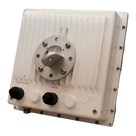
  9. Proxim Tsunami QB-8100 User manual

Proxim Tsunami QB-8100 User manual

Version 1.1 P/N 77062 1 Copyrights © 2009 Proxim Wireless 2 3
Tsunami QB-8100
Quick Installation Guide
Introduction
The Tsunami QuickBridge 8100 is a wireless point-to-point networking solution for any
enterprise or small business markets. Two pre-configured bridges enable users to easily,
quickly, and economically install a wireless LAN extension between two locations,
eliminating the need for costly leased line or cable alternatives. The QuickBridge 8100 kit
contains everything you need to establish a point-to-point connection.
Products Covered in This Guide
Package Contents
Each QuickBridge 8100 Product package includes the items listed in the following table.
Verify that you have received all parts of the product package.
Note: Ethernet cables are not included with the product package.
Note: QB-8150-LNK Model contains two sets of the above accessories.
Unit’s Hardware Description
Note: In the connectorized version, if you use Single Polarization antenna,
always use the antenna port A1. If you use Dual Polarization antenna,
use the antenna port A1 and A3.
Install the Documentation and Software
1. Insert the CD into the CD-ROM drive. The installer starts automatically. If it does not,
double-click on the setup.exe on the installation CD and wait for the installation to
complete.
The following documentation and software products are installed:
• Documentation (in DOCS subdirectory):
— Installation and Management Guide
— Quick Installation Guide
— Reference Manual
— Antenna Installation Guide
— Recommended Antennas Guide
• Help (in Help subdirectory) – double-click on index.htm to access
• Scan Tool (in ScanTool subdirectory)
• TFTP Server (in Extras subdirectory)
• Adobe Reader (in Extras subdirectory)
Note: You need Acrobat Reader to view the PDF documents, which is
distributed with the Software CD.
Assemble the Cables
The following steps explain how to weatherproof the RJ45 connectors:
1. Slide the sealing nut (E) over the bare end of the Cat5e/Cat6 cable.
2. Slide the tube-shaped compression washer (C) into the compression ring (D) and onto
the Cat5e/Cat6 cable.
3. Insert the flat washer (A) into the connector body (B) to make it waterproof and screw
the connector body into the Ethernet connector hole.
4. Terminate the RJ45 connectors to both ends of the Cat5e/Cat6 cable and test for
proper wiring (cable should be a straight-through cable).
5. Slide the Cat5e/Cat6 cable through the Ethernet connector body (B) in to the Ethernet
jack inside the enclosure. The cable connector should latch into the jack.
6. Thread the sealing nut (E) onto the connector body (B) and hand tighten it to make a
waterproof compression around the cable.
7. Open the notch on both sides of the toroid and fix it on Ethernet Cat5e/Cat6 cable as
shown in the figure. Then, lock the notch of the Toroid by pressing it.
Note: The steps 1-6 apply for assembling the weatherproofing kit for Serial
cable. It is mandatory that both ethernet cables should be attached with
toroids that are provided in the product package.
Assemble the Mounting Hardware
Attach the mounting plate (A) using the provided screws and washers (Torque 9 N.m/75 in-
lbs), such that the unit’s antenna will be vertically and horizontally polarized when
mounted. Attach the extension arm (B) to mounting piece (A) with the screw, nut, and
washers provided, as shown below. The extension arm gives the unit more possible tilt,
letting you adjust for azimuth or elevation over a larger angle. Attach the mounting bracket
(C) to extension arm (B) with the screw, nut, and washers provided. Tighten the assembly
(Torque 15 N•m/130 in-lbs). The last figure shows the full assembly attached to the unit.
Note: This figure is for illustration only. Units should be mounted in square
position with connectors facing downward.
Mount the Unit
1. To pole-mount the unit, insert the provided screws through bracket (F). Fasten around
the pole to bracket (C) and secure (Torque 11 N.m/100 in-lbs).
2. To wall-mount the unit, mount the bracket to a wall using 4 screws (not provided), as
shown below.
Model Description
QB-8150-LNK Wireless Outdoor QuickBridge Link, Two Paired End Points
with Integrated Antenna, operating in 5 GHz band.
QB-8150-EPR Wireless Outdoor QuickBridge End Point with Integrated
Antenna operating in 5GHz Band.
QB-8100-EPA Wireless Outdoor QuickBridge End Point with 3 N-Type
connectors, operating in 2.4/5GHz Bands.
What’s in the Kit Image
Unit
Integrated Connectorized
Power Injector & Cord
RJ11 to DB9 serial connec-
tor
IMPORTANT
This device must be installed by a trained professional, value added reseller or
systems integrator who is familiar with RF planning issues and the regulatory
limits.
CAUTION!
For Regulatory Information and latest product updates, including firmware
and the MIBs, Proxim recommends visiting the Proxim Support site at
http://support.proxim.com.
WARNING!
When connecting a device to the second Ethernet port (Eth2), Proxim
recommends to verify if it is a 802.3af compatible device. If you are planning to
use any other device, please insert a power splitter (not supplied) between the
second Ethernet port and the device, otherwise it may damage the device.
or
Mounting Kit and Hardware
Installer CD and Quick
Installation Guide
Gigabit Ethernet PoE Surge
Arrestor
Grounding Kit
EMI Toroid
What’s in the Kit Image
4 5 6
1561 Buckeye Drive,
Milpitas, California 95035
Phone: (408) 383-7700
Fax: (408) 383-7680
Plug in the Cables
Note: Unscrew the sealing cap for installation of the cable.
1. Plug one end of the Cat5e/Cat6 cable (Eth1) into the Ethernet (RJ45) jack of the Eth1
interface inside the enclosure. Plugging in the second Cat5e/Cat6 cable to Eth2
interface is optional. Ensure that the cable connector is latched securely and the
Toroids are fixed on the cable. You can hear a click sound when the cable connector
latches into the jack, then tighten the sealing nut by hand.
2. Plug the Serial cable into the serial RJ11 telephone jack inside the enclosure. (leftmost
cable in the picture below) Tighten the sealing nut by hand.
3. Connect the other end of the first CAT5e/Cat6 cable (Eth1) to the “PWR LAN-OUT”
port on the power injector.
Warning: A tension of 48 VDC (15 W average) is present on the second ethernet
port (Eth2). Make sure the connected device can support this tension on its
ethernet port.
Warning: Connect network devices only into the LAN-IN port of the Power injector.
The PWR LAN-OUT port is meant to power the QB-8100 unit.
4. To connect the QB-8100 unit through a hub or a switch to a PC, connect an Ethernet
cable between the network interface card in the PC and the hub and between the
hub and the RJ45 “LAN-IN” port on the PoE adapter.
5. To connect the QB-8100 unit directly to a PC, connect an Ethernet cable between the
network interface card in the PC and the RJ45 “LAN-IN” port on the power injector.
Connect the Antenna (Connectorized Version Only)
Connect the antenna with N-male cables to the antenna connectors on the device.
Note: Write down the ports to which you have connected the antenna. This
will be useful during the configuration of MIMO parameters.
Units with integrated antennas must always be mounted in square position to achieve
Horizontal and Vertical polarization.
Install Surge Protector
Proxim recommends two approved lightning surge protectors to be installed, one near to
the device (supplied with the product package) and the other near to the building ingress
point.
Perform the following steps to ensure proper surge protection:
1. Mount the provided surge protector near the outdoor equipment and use 10 AWG or
larger wire to connect the protector’s ground lug to the appropriate mounting ground
point. The outdoor equipment and co-located surge protector should have a common
grounding point using the shortest possible grounding cable
2. Mount a second surge protector near the building ingress and use 10 AWG or larger
wire to connect the protector’s ground lug to earth ground as shown in the following
figure.
Note: Use Outdoor-rated, UV protected, shielded Cat5e/Cat6 cable for the
following.
3. Connect an RJ45 terminated cable between the indoor equipment and to the port on
the surge protector at the building ingress.
4. Connect a short RJ45 terminated cable between the outdoor equipment and the port
on the co-located surge protector.
5. Connect an RJ45 terminated cable between the two surge protectors on their
remaining ports.
Ground the Unit
To ensure proper grounding, use either of the ground points which are situated at the
bottom corners of the unit and the grounding screw provided to attach a ground wire of at
least 10 AWG stranded to the unit. It is important that the following ground guidelines are
followed during installations:
1. Cut any extra ground wire length when finished connecting it to the single point earth
ground.
2. Avoid sharp bends and never loop or coil up the ground wire, always connect it
straight to ground.
3. A good earth ground impedance is less than 1.0 ohm.
4. Measure ground impedance at the point where the protector ground wire is
connected and not at the ground rod.
5. Connect the protector ground wire and equipment ground (both power ground and
telecomm ground) to a single common ground.
6. Make sure all connections are fastened securely and are tight.
7. Never install during a storm and always follow your local safety codes.
Connect the grounding wire, which is supplied with the product package, to the grounding
lug as shown below:
.
Power on the Unit
Plug in the power cord into a power outlet after having connected the Power Injector and
the Radio device using Cat5e/Cat6 cable. There is no ON/OFF switch on the unit. To
disconnect power, unplug the RJ45 connector from the “PWR LAN-OUT” port on the
power injector.
View LEDs
When the device is powered on, it performs startup diagnostics. When startup is complete,
the LEDs show the unit’s operational state. The LEDs are available at the unit’s Ethernet
connector inside the enclosure. You can see the LEDs through the ethernet connector. The
LEDs will not be visible when the weather-sealing caps are installed.
The following table describes the status of LEDs:
Align the Antenna
The units have an audible antenna alignment tool that can be activated by plugging in the
serial dongle (supplied) or by issuing the CLI command for antenna alignment (see
“Antenna Alignment Commands” in Tsunami QB-8100 Installation & Management Guide).
Initialize the Device
IP address of the device can be configured using HTTP, TELNET, SNMP, or CLI and also using
scan tool.
The following are the default access values of the device:
• IP Address: End Point A 169.254.128.132
End Point B 169.254.128.131
• Gateway: 169.254.128.132
• Username: admin
• Password: public
• SNMP Read Write Community String: public
Technical Support
Proxim eService Web Site Support
• Proxim eService Website is available 7x24x365 at: http://support.proxim.com
Telephone Support
•US and Canada: 408-383-7700, 866-674-6626 (Toll Free)
Hours of Operations: 6.00 AM-6.00 PM, Monday-Friday, Pacific Time
•APAC Countries: +91 40 23115490
Hours of Operations: 9.00 AM-6.00 PM, Monday-Friday, IST Time (UTC/GMT
+5.30 Hrs.)
•International: 408-383-7700
Hours of Operations: 6.00 AM-6.00 PM, Monday-Friday, Pacific Time
ServPak Support
• Advanced Replacement and Extended Warranty
• 7x24x365 Technical Support
• Priority Queuing
To learn more, call Proxim Support at 408-383-7700 or send an email to
[email protected]. To purchase ServPak support services, contact your authorized
Proxim distributor.
LED State Eth1
Wireless LED Power/Ethernet LED
Yellow Power is on & unit
detects Reload signal
Unit is self heating (Cold Start)
Off Radio is not present or
failed to detect
No Power
Blinking
Green-Fast
Radio is on and wireless
link has not been estab-
lished yet
Power is on and the Ethernet Eth1 link is
down
Blinking
Green-Slow
NA Bootloader detected no image
Green A wireless link has been
established
Power is on and the Ethernet link Eth1 is
up
LED State Eth2
Wireless LED Power/Ethernet LED
Yell ow NA -
Off Normal Operation No Power
Blinking
Green-Fast
NA Power is on and the Ethernet link Eth2 is
down
Blinking
Green-Slow
NA Bootloader detected no image
Green NA Power is on and the Ethernet link Eth2 is
up

Other Proxim Network Hardware manuals

Proxim Antenna Tsunami MP.11 Programming manual

Proxim

Proxim Antenna Tsunami MP.11 Programming manual

Proxim 6221e User manual

Proxim

Proxim 6221e User manual

Proxim Tsunami QuickBridge 2454-R Programming manual

Proxim

Proxim Tsunami QuickBridge 2454-R Programming manual

Proxim Tsunami QuickBridge II T1/E1 User manual

Proxim

Proxim Tsunami QuickBridge II T1/E1 User manual

Proxim ORiNOCO AP-4000 User manual

Proxim

Proxim ORiNOCO AP-4000 User manual

Proxim Lynx.GX 4T Programming manual

Proxim

Proxim Lynx.GX 4T Programming manual

Proxim Symphony HomeRF Base Station User manual

Proxim

Proxim Symphony HomeRF Base Station User manual

Proxim Tsunami QuickBridge 2454-R User manual

Proxim

Proxim Tsunami QuickBridge 2454-R User manual

Proxim 6221e User manual

Proxim

Proxim 6221e User manual

Proxim MP11 5012-SUI User manual

Proxim

Proxim MP11 5012-SUI User manual

Proxim Tsunami QuickBridge.11-R Series User manual

Proxim

Proxim Tsunami QuickBridge.11-R Series User manual

Proxim Antenna Tsunami MP.11 Programming manual

Proxim

Proxim Antenna Tsunami MP.11 Programming manual

Popular Network Hardware manuals by other brands

HP Mv2120 - Media Vault Network Drive user guide

HP

HP Mv2120 - Media Vault Network Drive user guide

KT&C ENRSeries user manual

KT&C

KT&C ENRSeries user manual

Advantech FWA-3232 Startup manual

Advantech

Advantech FWA-3232 Startup manual

Garland INT40G2SR44 user guide

Garland

Garland INT40G2SR44 user guide

Sure-Fi, Inc. SFI-AB401-01 Operator's manual

Sure-Fi, Inc.

Sure-Fi, Inc. SFI-AB401-01 Operator's manual

Polycom V2IU 4300T Series user guide

Polycom

Polycom V2IU 4300T Series user guide

Avocent MERGEPOINT 53XX SP MANAGER Installer/user guide

Avocent

Avocent MERGEPOINT 53XX SP MANAGER Installer/user guide

Detexi Nework Video Recorder user manual

Detexi

Detexi Nework Video Recorder user manual

Bauhn ASPP4-0722-B user guide

Bauhn

Bauhn ASPP4-0722-B user guide

ADC OmniReach oFDT-48 Specification sheet

ADC

ADC OmniReach oFDT-48 Specification sheet

Grandstream Networks UCM6510 user manual

Grandstream Networks

Grandstream Networks UCM6510 user manual

Seagate Mirra Specifications

Seagate

Seagate Mirra Specifications

ABB iPAQ user manual

ABB

ABB iPAQ user manual

Pacific Communications SmartIP-8SD user manual

Pacific Communications

Pacific Communications SmartIP-8SD user manual

D-Link ShareCenter Quattro DNS-345 Specifications

D-Link

D-Link ShareCenter Quattro DNS-345 Specifications

Nokia G-240W-J Quick reference guide

Nokia

Nokia G-240W-J Quick reference guide

FieldServer X-25 Startup guide

FieldServer

FieldServer X-25 Startup guide

ZyXEL Communications Prestige 1600 Configuration guide

ZyXEL Communications

ZyXEL Communications Prestige 1600 Configuration guide

manuals.online logo
manuals.online logoBrands
  • About & Mission
  • Contact us
  • Privacy Policy
  • Terms and Conditions

Copyright 2025 Manuals.Online. All Rights Reserved.