Prozone RCQD User manual

92-100105-05-00
INSTALLATION INSTRUCTIONS
FOR RCQD COILS
RECOGNIZE THIS SYMBOL AS AN INDICATION OF IMPORTANT SAFETY INFORMATION!
!
DO NOT DESTROY THIS MANUAL
PLEASE READ CAREFULLY AND KEEP IN A SAFE PLACE FOR FUTURE REFERENCE BY A SERVICEMAN
THESE INSTRUCTIONS ARE INTENDED AS AN AID TO
QUALIFIED, LICENSED SERVICE PERSONNEL FOR PROPER
INSTALLATION, ADJUSTMENT AND OPERATION OF THIS UNIT.
READ THESE INSTRUCTIONS THOROUGHLY BEFORE
ATTEMPTING INSTALLATION OR OPERATION. FAILURE TO FOL-
LOW THESE INSTRUCTIONS MAY RESULT IN IMPROPER
INSTALLATION, ADJUSTMENT, SERVICE OR MAINTENANCE
POSSIBLY RESULTING IN FIRE, ELECTRICAL SHOCK,
PROPERTY DAMAGE, PERSONAL INJURY OR DEATH.
WARNING
!
refrigerant
f
2
TABLE OF CONTENTS
Model Number Explanation . . . . . . . . . . . . . . . . . . . . . . . 2
Unit Specifications . . . . . . . . . . . . . . . . . . . . . . . . . . . . . . 3
Airflow Pressure Drop . . . . . . . . . . . . . . . . . . . . . . . . . . . 4
Coil Application. . . . . . . . . . . . . . . . . . . . . . . . . . . . . . . . . 5
INSPECTION . . . . . . . . . . . . . . . . . . . . . . . . . . . . . . . . . . 5
GENERAL INFORMATION . . . . . . . . . . . . . . . . . . . . . . . 5
Codes/Regulations. . . . . . . . . . . . . . . . . . . . . . . . . . . . . . 5
Replacement Parts. . . . . . . . . . . . . . . . . . . . . . . . . . . . . . 5
INSTALLATION. . . . . . . . . . . . . . . . . . . . . . . . . . . . . . . . 6
Vertical Upflow/Downflow. . . . . . . . . . . . . . . . . . . . . . . . . 6
Horizontal. . . . . . . . . . . . . . . . . . . . . . . . . . . . . . . . . . . . . 6
Refrigerant Connections. . . . . . . . . . . . . . . . . . . . . . . . . . 7
Horizontal Drain Pan Extension . . . . . . . . . . . . . . . . . . . . 7
TXV Sensing Bulb . . . . . . . . . . . . . . . . . . . . . . . . . . . . . . 7
Condensate Drain Tubing . . . . . . . . . . . . . . . . . . . . . . . . 7
MAINTENANCE. . . . . . . . . . . . . . . . . . . . . . . . . . . . . . . . 8
Air Filter . . . . . . . . . . . . . . . . . . . . . . . . . . . . . . . . . . . . . . 8
Indoor Coil . . . . . . . . . . . . . . . . . . . . . . . . . . . . . . . . . . . . 8
ACCESSORIES . . . . . . . . . . . . . . . . . . . . . . . . . . . . . . . . 8
Plenum Adapter Accessory . . . . . . . . . . . . . . . . . . . . . . . 8
Sweat
Variation
A - 16 & 18 SEER Application
Coil Casing
17 = 17" [431.8 mm]
21 = 21" [533.4 mm]
24 = 24" [609.6 mm]
Nominal Capacity
24 = 24,000 BTUH
[7.03 kW]
36 = 36,000 BTUH
[10.55 kW]
48 = 48,000 BTUH
[14.06 kW]
Design Series
Type of Coil
Q = High Efficiency AC/Heat Pump Coil
with Expansion Valve
Coil
TRADE NAME
FIGURE 1
MODEL NUMBER EXPLANATION
RCQD—2417AS

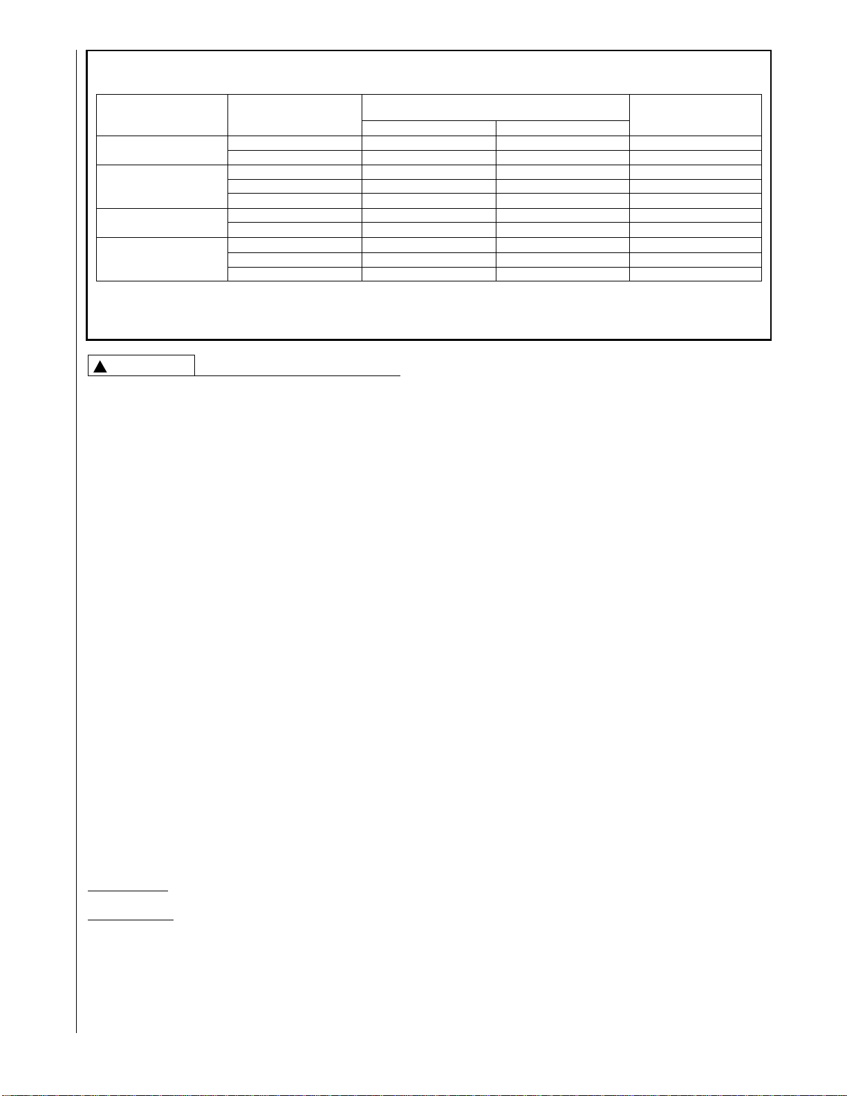
FIGURE 2
UNIT SPECIFICATIONS
3
3/4 NPT DRAIN
(SECONDARY)
3/4 NPT DRAIN
(PRIMARY)
3-3/8
A
B
SUCTION LINE
LIQUID LINE
1-51/64
C
7-5/8 5-5/8
22
AIRFLOW
FRONT VIEW
PLENUM WIDTH
SIDE VIEW
197/8
Coil
Model
Number
Connections Dimensions (in.) [mm] – Weight (lbs.) [Kg]
Sweat (in.) [mm]
ABC
Coil Weight
(lbs.) [Kg] Shipping Weight
(lbs.) [Kg]
Liquid Suction
I.D. I.D.
RCQD-2417AS 3/8 [9.53] 3/4 [19.05] 17-1/2 [445] 19-7/8 [505] 28 [711] 59 [27] 67 [30]
RCQD-3621AS 3/8 [9.53] 7/8 [22.23] 21 [533] 24-3/4 [629] 28 [711] 74 [34] 83 [38]
RCQD-3624AS 3/8 [9.53] 7/8 [22.23] 24-1/2 [622] 24-3/4 [629] 28 [711] 80 [36] 90 [41]
RCQD-4821AS 3/8 [9.53] 7/8 [22.23] 21 [533] 24-3/4 [629] 28 [711] 74 [34] 83 [38]
RCQD-4824AS 3/8 [9.53] 7/8 [22.23] 24-1/2 [622] 24-3/4 [629] 28 [711] 80 [36] 90 [41]
DIMENSIONS AND WEIGHTS DATA
“A” Minus One Inch

4
TABLE 1
COIL SPECIFICATIONS / AIRFLOW PRESSURE DROP
Model
Number
RCQD-
2417AS U-H 450/800 4.38 14/3 0.06 0.10 0.14 0.17 0.21 0.25 0.29
[212/378] [0.41] [.015] [.024] [.035] [.042] [.052] [.062] [.072]
3621AS U-H 720/1200 5.83 14/3 0.08 0.10 0.13 0.16 0.18 0.21
[340/566] [0.54] [.02] [.025] [.032] [.04] [.045] [.052]
3624AS U-H 720/1200 5.83 14/3 0.07 0.09 0.11 0.13 0.15 0.17
[340/566] [0.54] [.017] [.022] [0.27] [0.32] [0.37] [0.42]
4821AS U-H 960/1600 5.83 14/3 0.14 0.17 0.19 0.22 0.25 0.29 .032
[453/755] [0.54] [.035] [.042] [.047] [.055] [.062] [.072] [.08]
4824AS U-H 960/1600 5.83 14/3 .11 .13 .15 .17 .19 .23 .25
[453/755] [0.54] [.027] [.032] [.037] [.042] [.047] [.057] [.062]
HIGH EFFICIENCY COOLING COILS
Type
Air
Flow
➀
Approx.
Design
Air Flow
CFM [L/s]
Range
Face
Area
Sq. Ft.
[m2]
Fins-in.
Rows
Deep 600
[283] 700
[330] 800
[378] 900
[425] 1000
[472] 1100
[519] 1200
[566] 1300
[614] 1400
[661] 1500
[708] 1600
[755] 1700
[802] 1800
[850] 1900
[897]
Static Pressure Drop Through Wet Cooling Coil [kPa] (Inches H2O) CFM [L/s]
➀H = Horizontal airflow, U = Upflow
5
TABLE 2
COIL APPLICATION
Coil Model
RCQD Type Air
Flow* Oil Gas
Furnace Width
inches [mm] Plenum Adapter
Upflow
2417AS
3621AS
4821AS
3624AS, 4824AS
U-H
U-H
U-H
U-H
U-H
U-H
U-H
U-H
U-H
U-H
14 [356]
21 [533]
17-1/2 [445]
21 [533]
17-1/2 [445]
24-1/2 [622]
21 [533]
RXBA-AC
21 [533]
21 [533]
24-1/2 [622]
17-1/2 [445] N/A
N/A
RXBA-AC
N/A
RXBA-AC
N/A
N/A
RXBA-AC
N/A
NOTES:
* U = UPFLOW
H = HORIZONTAL
PROPOSITION 65: THIS APPLIANCE CONTAINS
FIBERGLASS INSULATION. RESPIRABLE PARTI-
CLES OF FIBERGLASS ARE KNOWN TO THE STATE
OF CALIFORNIA TO CAUSE CANCER.
All Rheem products meet current Federal OSHA
Guidelines for safety. California Proposition 65 warnings
are required for certain products, which are not covered
by the OSHA standards.
California's Proposition 65 requires warnings for products
sold in California that contain or produce any of over 600
listed chemicals known to the State of California to cause
cancer or birth defects such as fiberglass insulation, lead
in brass, and combustion products from natural gas.
All “new equipment” shipped for sale in California will
have labels stating that the product contains and/or pro-
duces Proposition 65 chemicals. Although we have not
changed our processes, having the same label on all our
products facilitates manufacturing and shipping. We can-
not always know “when, or if” products will be sold in the
California market.
You may receive inquiries from customers about chemi-
cals found in, or produced by, some of our heating and
air-conditioning equipment, or found in natural gas used
with some of our products. Listed below are those chemi-
cals and substances commonly associated with similar
equipment in our industry and other manufacturers.
• Glass Wool (Fiberglass) Insulation
• Carbon Monoxide (CO).
• Formaldehyde
• Benzene
More details are available at the websites for OSHA
(Occupational Safety and Health Administration), at
www.osha.gov and the State of California’s OEHHA
(Office of Environmental Health Hazard Assessment), at
www.oehha.org. Consumer education is important since
the chemicals and substances on the list are found in our
daily lives. Most consumers are aware that products pre-
sent safety and health risks, when improperly used, han-
dled and maintained.
I. INSPECTION
Immediately upon receipt, all cartons, and contents should
be inspected for transit damage. Units with damaged car-
tons should be opened immediately. If damage is found, it
should be noted on the delivery papers and a damage
claim filed with the last carrier.
• After unit has been delivered to job site, remove carton
taking care not to damage unit.
• Check the unit rating plate to be sure equipment match-
es what is required for the job specification.
• Read the entire instructions before starting the installa-
tion. This is particularly important if this is the first instal-
lation for this specific model series.
• Many installation steps done prior to setting the unit in
place can save time and simplify the installation.
II. GENERAL INFORMATION
CODES/REGULATIONS
Units should be installed in accordance with any local
code which may apply and the national codes. Latest edi-
tions are available from: “National Fire Protection
Association, Inc., Batterymarch Park, Quincy, MA 02269.”
These publications are:
• ANSI/NFPA Latest Edition (NEC) National Electrical
Code.
• NFPA90A Installation of Air conditioning and
Ventilating Systems.
• NFPA90B Installation of Warm Air Heating and Air
Conditioning Systems.
REPLACEMENT PARTS
Any replacement part must be the same as or an
approved alternate to the original part supplied. The man-
ufacturer will not be responsible for replacement parts not
designed to physically fit or operate within the design
parameters the original parts were selected for.
When ordering replacement parts, it is necessary to order
by part number and include the complete model number
and serial number from the unit rating plate. (See parts list
for unit component part numbers.)
WARNING
!

6
FIGURE 4
HORIZONTAL RIGHT INSTALLATION
III. INSTALLATION
COIL INSTALLATION
WHEN INSTALLING A UNIT WITH COOLING COIL OVER
A FINISHED CEILING AND/OR LIVING SPACE, INSTAL-
LATION OF A SECONDARY FIELD FABRICATED DRAIN
PAN UNDER THE ENTIRE UNIT, TO AVOID DAMAGE TO
CEILING, IS RECOMMENDED.
RCQD- coils can be applied in various upflow and horizon-
tal flow configurations. (See Figure 3. Refer to Table 2 for
approved applications).
FOR HORIZONTAL APPLICATIONS, THE HORIZONTAL
DRAIN PAN MUST BE LOCATED UNDER THE INDOOR
COIL. FAILURE TO PLACE THE PAN UNDER THE COIL
CAN RESULT IN PROPERTY DAMAGE.
FIGURE 3
FACTORY SHIPPED COIL INSTALLATION
UPFLOW
HORIZONTAL LEFT
CAUTION
!
CAUTION
!
VERTICAL UPFLOW AND
HORIZONTAL LEFT INSTALLATION
(SEE FIGURE 3)
1. For vertical or horizontal left installation, no modifica-
tion from current factory configuration is required.
2. Seal the gap around the refrigerant lines with the per-
magum provided in the parts bag.
NOTE: The coil is shipped from factory for the vertical or
horizontal left position. The coil must be converted for use
in horizontal right position.
VERTICAL DOWNFLOW
IMPORTANT: The RCQD-series coil is not approved for
vertical downflow applications.
SEVERE CONDENSATE BLOWOFF CAN OCCUR IF THE
RCQD COIL IS APPLIED IN A VERTICAL DOWNFLOW
APPLICATION.
CAUTION
!
7
HORIZONTAL LEFT INSTALLATION
All RCQD-series coils are shipped for vertical and horizon-
tal left applications. Conversion is required for horizontal
right applications.
HORIZONTAL RIGHT INSTALLATION
(SEE FIGURE 4)
THE FOLLOWING COIL MODIFICATIONS MUST BE IMPLEMENTED:
1. Remove the entire front panel assembly by removing
all necessary screws.
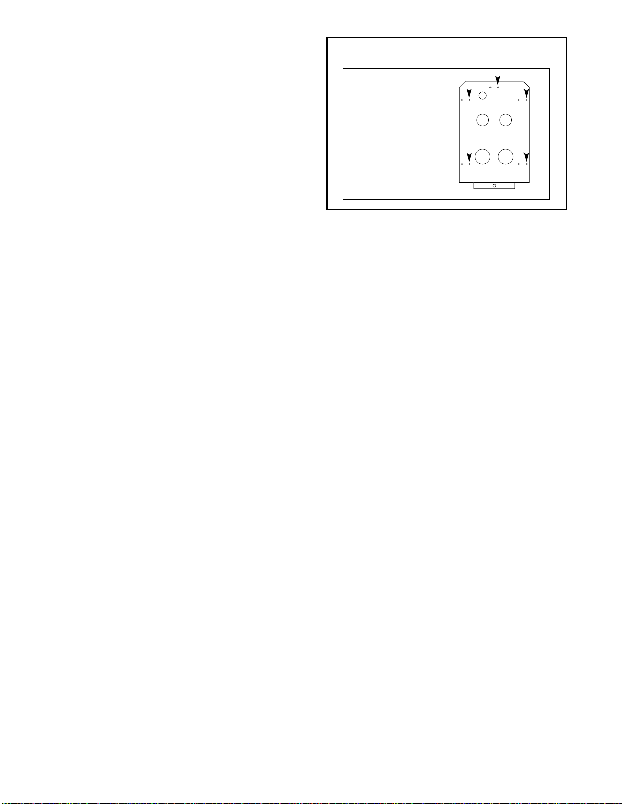
2. Remove the refrigerant access panel from the front
panel and reinstall it with the right-hand side mounting
holes (see Figure 5).
3. Switch the positions of the left condensate plate and
right blank plate on the front panel.
4. Slide the coil outside of the coil box.
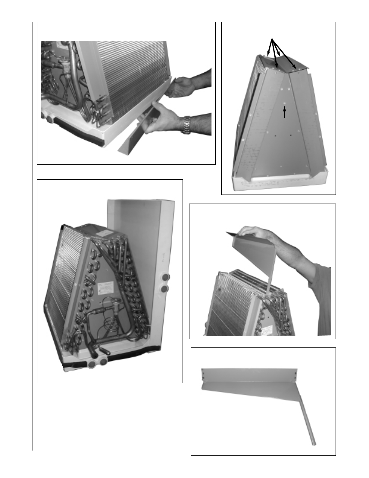
5. Remove the vertical bracket on the right side of the
vertical drain pan (see Figure 6).
6. Remove the horizontal drain pan and place it on the
right side of the coil (see Figure 7).
7. Re-install the vertical bracket on the left side of the
vertical drain pan.
8. Remove all screws from the top of the air stop (see
Figure 8).
9. Remove the center drain trough by removing the
screw located at the back triangular plate (see Figure
8). Ensure glue stop on the bottom of the drain trough.
10. Rotate the center drain trough 180°, front to back (see
Figure 9).
NOTE: Failure to properly rotate the center drain
trough may permit condensate water to blow off the
cooling coil.
11. Apply permagum supplied in parts bag to underside of
drain trough (see Figure 10) in four corners.
12. Re-install the center drain trough and secure it by
tightening the screw through the hole located on the
front triangular plate. Reinstall the top air stop.
13. Replace the coil assembly into the coil box (be sure to
align the vertical brackets properly with the side rail),
taking care not to tear insulation.
14. Locate TXV sensing bulb and slide it through the uni-
versal grommet on the access panel.
15. Reinstall front panel.
16. Seal the gap around the refrigerant lines with the per-
magum provided in the parts bag.
REFRIGERANT CONNECTIONS
Keep the coil connections sealed until refrigerant connec-
tions are to be made. See the Installation Instructions for
the outdoor unit for details on line sizing, tubing installation,
and charging information.
Install refrigerant tubing so that it does not block service
access to the front of the unit.
Use a brazing shield to protect the cabinet’s paint from
being damaged by torch flames.
Coil is shipped with a low (5 - 10 PSIG) pressure charge of
dry nitrogen. Evacuate the system before charging with R-
410A refrigerant.
TXV SENSING BULB
IMPORTANT: Do not perform any brazing with the TXV bulb
attached to the line.
After brazing operations have been completed, clamp the TXV
bulb securely on the suction line at the 2 o’clock position with
the strap provided in the parts bag.
Insulate the TXV sensing bulb and suction line with the provid-
ed pressure sensitive insulation (size 4” x 7”) and secure with
provided wire ties.
NOTE: TXV sensing bulb should be located on a horizontal
section of suction line, just outside of coil box.
CONDENSATE DRAIN TUBING
Consult local codes or ordinances for specific requirements.
IMPORTANT: When making drain fitting connections to drain
pan, use a thin layer of teflon paste, silicone or teflon tape and
install hand tight.
IMPORTANT: When making drain fitting connections to drain
pan, do not overtighten. Overtightening fittings can split pipe
connections on drain pan.
• Do not reduce drain line size less than connection size pro-
vided on condensate drain pan.
• All drain lines must be pitched downward away from the unit
a minimum of 1/8” per foot of line to ensure proper drainage.
• Do not connect condensate drain line to a closed or
open sewer pipe. Run condensate to an open drain or
outdoors.
• The drain line should be insulated where necessary to
prevent sweating and damage due to condensate form-
ing on the outside surface of the line.
• Make provisions for disconnecting and cleaning of the
primary drain line should it become necessary. Install a
2 in. trap in the primary drain line as close to the unit as
possible. Make sure that the top of the trap is below
connection to the drain pan to allow complete drainage
of pan (see Figure 5).
FIGURE 5
REFRIGERANT ACCESS PANEL
NOTE: WHEN CON-
VERTING TO HORIZON-
TAL RIGHT INSTALLA-
TION, USE THE RIGHT-
HAND SIDE MOUNTING
HOLES IN THE REFRIG-
ERANT ACCESS
PANEL
8
FIGURE 6
VERTICAL BRACKET
FIGURE 10
PERMAGUM APPLICATION
FIGURE 9
ROTATE DRAIN TROUGH
FIGURE 7
DRAIN PAN PLACEMENT
FIGURE 8
AIR STOP
SCREWS SCREW
REMOVAL
DRAIN
TROUGH
SCREW

9
FIGURE 11
CONDENSATE DRAIN TRAP
DO NOT OPERATE UNIT WITHOUT
CONDENSATE DRAIN TRAP.
UNIT MUST BE SLOPED
TOWARD DRAIN CONNECTION.
DO NOT OVERTIGHTEN DRAIN FITTING
UNIT
2''
• Auxiliary drain if used should be run to a place
where it will be noticeable if it becomes operational.
Occupant should be warned that a problem exists if
water should begin running from the auxiliary drain
line.
• Test condensate drain pan and drain line after instal-
lation is complete. Pour several quarts of water into
drain pan, enough to fill drain trap and line. Check to
make sure drain pan is draining completely, no leaks
are found in drain line fittings, and water is draining
from the termination of the primary drain line.
V. ACCESSORIES
PLENUM ADAPTER ACCESSORY
RXBA-AC
This plenum adapter accessory is for installation on
cased indoor cooling and heat pump coils. This allows a
nominal size cased coil to be installed on the next small-
er size gas or oil furnace. NOTE: This accessory is for
installation on coil casings to fit gas or oil furnaces
only - this accessory must not be used on electric
furnaces or heat pump air handlers. Consult the instal-
lation instructions packaged with the accessory for prop-
er installation. The RXBA-AC (upflow) can be ordered
factory installed by designation as “with adapters” in the
coil model number.
PLENUM ADAPTER ACCESSORY
RXBA-AE
This plenum adapter accessory is for use with the 24-1/2"
wide cased indoor cooling and heat pump coils. This
allows a 24-1/2” wide cased coil to be installed on a 28”
wide oil furnace. This is a field installed accessory only.

10

11

12 CM 1004
Table of contents
Other Prozone Industrial Equipment manuals


