Prozone ProR221J User manual

Zones
Heating and Cooling Stages
Rev G Aug 2015
Bypass Control
Optional Sensors
Panel Power
Warranty
Wiring
Humidity Rating
Temperature Ratings
Dampers per Zone
Compatible Equipment
Equipment Selection
The panel can be used with traditional mechanical barometric
dampers, adjusting the close position limit on each zone
damper or use the non-calling zone dampers for bypass.
Discharge air (Model TS2) and outdoor air temperature sensor
(Model TS3) can be used. A pressure sensor (Model PS2) can
be used to monitor duct pressure.
24VAC (18 to 30), 10VA
5-year warranty limited to repair or replacement of panel due to
defective material or workmanship.
Use 18 or 20 AWG solid thermostat wire.
5 to 90% RH non-condensing.
Shipping o o o o
-20 to 150 F (-29 to 66 C)
o o o o
0 to 165 F (-32 to 74 C)
Operating
Multiple dampers may be used to configure a zone. The total
number of dampers that can be used depends on the VA
rating of the 24VAC transformer used. Up to six dampers can
be daisy chained to configure a zone.
All panels operate with gas/electric systems, conventional heat
pumps and dual fuel heat pumps.
Selected using the jumper plugs on the panel. See table
below.
See table below.
See table below.
HVAC PANEL ZONE DAMPERS
1 12 23
Fresh
Air
3
THERMOSTATS
Quick View
Zoning Panel
ProZone
7-5/8 (193)
9-5/8 (244)
1-5/8 (41)
Compatible Dampers
The ProR80J-XX dampers with plug and play cables. Each
damper is supplied with a 25-foot cable.
Compatible Thermostats
Compatible Thermostat Types
When gas/electric equipment is selected, heat/cool thermostats
are used in all zones. When heat pump equipment is selected,
a heat pump or heat/cool thermostat may be used in Zone1
and heat/cool thermostats are used in all other zones.
Single stage, 24VAC powered or battery powered thermostats.
ZonePro
I n t e l l i g e n t Z o n i n g
Installation Guide
ProR221J, ProR212J, ProR321J and ProR312J
Zones on Panel Two Two
No No
Two One
One Two
One Two
One None One None
Two
One
One
One
Two
Two
No. No.
Three Three
Model ProR221J Model ProR212J Model ProR321J Model ProR312J
Expandable
Heating Stages
Compressor Stages
Cooling Stages
Auxiliary Heating Stages
Gas/Electric Equipment
Heat Pump Equipment

Relay
Relay
Relay
Relay
DMPR1
DMPR2
DMPR3
PANEL
FAD HVAC
TSTAT1
TSTAT2
TSTAT3
R
O
B/W1
Y
G
HVAC EQUIPMENT
ZONE
DAMPER
1
ZONE
DAMPER
2
ZONE
DAMPER
3
FRESH
AIR
DAMPER
W2/E
COM
COM
24V
24VAC
GND
PRS
OAT
LAT
OAT
LAT
+VDC
SENSORS
ProZone
ProR321J
R
R
R
C
C
C
W1/OB
W
W
W2/E
Y
Y
Y
G
G
G
ZONE1 TSTAT
ZONE2 TSTAT ZONE3 TSTAT
Features
ProR Series Zoning Panels
Model ProR321J Shown
Multi-color LEDs indicate zone
thermostat call status.
Green for cooling call.
Blinks yellow during timing delays, purge
or supply air temperature limit.
Red for heating call.
Blinks red if sensor failure detected.
Blinks green when operating normally.
Green when damper open.
Off when damper is closed.
Yellow for fan call.
Blinks for staged call or Em Heat.
LED is green when fresh air
damper is open.
LEDs indicate zone
damper position.
Multi-color LEDs indicate
equipment call status.
Jumper plugs for selecting
type of equipment.
Multi-color LEDs indicate
zoning panel status.
Terminals for gas/electric
systems or heat pumps.
2-heat, 1-cool or
1-heat, 2-cool.
Connectors for plug and
play dampers.
Connector for plug and
play damper for fresh air
intake and exhaust per
ASHRAE 62.2 and Title24 .
24VAC power for panel
and dampers.
Electronic circuit breaker/fuse.
Connectors for PDMi3 carried by installer for setting
advanced options, cloning and monitoring installation.
Provided free to qualified contractors.
Terminals for optional duct pressure
sensor (PS2).
Terminal for optional outdoor temperature
sensor (TS3) for dual fuel HPs.
Terminals for leaving air temperature sensor
(TS2) to prevent over-heating the plenum or
freezing the indoor coil.
Color coded terminals for
heat/cool or heat pump
thermostat. Thermostat
type automatically selected.
Color coded terminals for
heat/cool thermostat.
Use 24VAC powered or
battery powered thermostats.
2

COM
COM
24V
24VAC
Mounting Panel Selecting Transformer
Remove the top cover and attach the panel to a wall close to
the unit using four #8 screws.
The VA rating of the transformer depends on the number of
actuators being used. The table below shows the VA required
for each zoning component including the ProR80J dampers.
The table below shows the number of dampers that can be
used with a 3 -zone installation using a 40, 60 or 75VA
transformer and ProR80J dampers.
Install the 24VAC transformer according to local electrical
codes and connect the 24VAC output to the terminals on the
panel using 2-conductor, 18 gage, thermostat wire as shown
below.
1. 3.
HVAC PANEL ZONE DAMPERS
11
22
3
FAD 3
THERMOSTATS
Quick Vi ew
ProR321J Zoning Panel
ProZone
Two #8 screws
Two #8 screws
Panel
3-Zone
Maximum VA
40VA Transformer
60VA Transformer
75VA Transformer
10VA
11 Dampers 19 Dampers 26 Dampers
1.8VA
2.4VA
Typical VA
10VA
1.0VA
1.0VA
Zone Thermostat
Zone Damper
Line
24VAC
2-conductor, 18 gage
Thermostat Wire
3
Selecting Equipment
Jumper plugs are used to select the equipment type. The panel
is shipped with the jumper plugs in the Gas/Electric position. To
change equipment type, remove the jumper plug(s) and place
in the correct position as shown below. Use the PDMi3 to
change zone sizes, bypass options, fresh air control, staging
and much more.
2.
Jumper plug
GE
CHP
HP
DFHP
Gas/Electric selected.
GE
CHP
HP
DFHP
Conventional Heat Pump selected.
GE
CHP
Dual Fuel Heat Pump selected.
HP
DFHP

R
C
W1/OB
W2/E
Y
G
ZONE1 TSTAT
R
C
W1/OB
W2/E
Y
G
ZONE1 TSTAT
Zone 2 or 3 Thermostat
Heat/Cool
24VAC
R
C
W1/OB
W2/E
Y1
Y2
G
Zoning Panel
Wiring Zone Thermostats
Heat/Cool Thermostats
Heat Pump Thermostats with Auxiliary Heating
Gas/electric systems using Heat/Cool thermostats. Wiring for
these thermostats is shown below.
Heat/Cool thermostats can be used in all zones. A heat pump
thermostat can be used in Zone1 with heat pump equipment to
control emergency heating. The type of thermostat can be
selected using the PDMi3.
6.
A heat pump thermostat should be used in Zone1 when heat
pump equipment is selected. Wiring of a heat pump zone
thermostat is shown below.
R
C
W1
Y1
G
ZONE2 TSTAT
R
C
W
Y
G
R
C
W1
Y1
G
Zoning Panel
Thermostat
R
C
Y or Y1
G
Zoning Panel
R
C
24VAC
24VAC Common
Cooling, Stage1
Indoor Fan
Y
G
Terminal Function
W1 Stage1 Heating
W
Zoning Panel
Zone 1 Thermostat
Heat/Cool
24VAC
Thermostat
R
C
Y or Y1
G
Zoning Panel
R
C
24VAC
24VAC Common
Cooling, Stage1
Indoor Fan
Y
G
Terminal Function
W1/OB Stage1 Heating
W1/OB
Inside
Day
Th
MODEMENU FAN SYSTEM
Schedule Auto
Heat
Heat
Set To
AM
Inside
Day
Th
MODEMENU FAN SYSTEM
Schedule Auto
Heat
Heat
Set To
AM
Inside
Day
Th
MODEMENU FAN SYSTEM
Schedule Auto
Heat
Heat
Set To
AM
4
ZONE
DAMPER
3
Installing Dampers
Wiring Dampers
One or more dampers can be used to define a zone. Dampers
should be installed in the duct or ducts and sealed to insure no
air leakage. Shown below is the ProR80J-XX damper.
The dampers are connected to the zoning panel with the cables
provided with each damper.
4.
5.
Zoning Panel
25-foot RJ12 cable
supplied with damper.
Plug damper cable into the
Zone Damper connector on
the zoning panel.
Daisy chained dampers
when more than one
damper required to
configure a zone.
AIRFLOW
Model ProR80J-008
ProZone
Inte lligent Zoning
IN
OUT
Model A80-MJ
Modulating Position
Damper Actuator
24VAC, 2.2VA
Made in USA
ProZone
IN
OUT
Model A80-MJ
Modulating Position
Damper Actuator
24VAC, 2.2VA
Made in USA
ProZone

R
O
B/W1
Y
G
HVAC EQUIPMENT
W2/E
Heat Pump System with Auxiliary Heat
Conventional and dual fuel heat pumps are wired the same as
shown below. The Auxiliary heat or Emergency heat on a
conventional heat pump is an electric strip heater and a gas
furnace on a dual fuel heat pump and connected to the W2/E
terminal on the panel.
6-conductor
18 gage
Thermostat Wire
Model ProR221J
or ProR321J
Line
24VAC
O Rev Valve
O
R
E
Y1
G
Aux Heat
Compressor1
Indoor Fan
Zoning Panel
O
R
W2/E
Y
G
Equipment Terminal Function
O-type Reversing Valve
24VAC
Auxiliary Heating
Compressor Stage1
Indoor Fan
O
R
W1 or E
Y1
G
Optional Sensors
Outdoor Temperature Sensor (Model TS3)
The outdoor temperature sensor (TS3) is required for dual fuel
heat pumps. The panel automatically switches to fossil fuel
heating when the outdoor temperature drops below the preset
o
40 F. The temperature limit can be changed using the PDMi3
carried by the installer.
The outdoor temperature can also be used to limit staging in
moderate weather. This option can be turned on using the
PDMi3 carried by the installer.
8.
1
2
3
Wall
45
6
5
G
G
HVAC EQUIPMENTHVAC EQUIPMENT
W2/E
Y2
R
R
O
O
B/W1
B/W
Y
Y1
Wiring HVAC Equipment
Gas/Electric System, Two-Stage Heat
Gas/Electric System, Two-Stage Cool
Gas/Electric systems using a single 24VAC transformer are
wired as shown below.
Gas/Electric systems using a single 24VAC transformer are
wired as shown below.
When using a heat pump thermostat, on the thermostat select
O operation of the reversing valve. If both an O and B terminal
is provided on the thermostat, wire the thermostat O terminal to
the W1/OB terminal at the Zone1 thermostat terminals.
7.
Thermostat
R
C
OB
W2/E
Y1
G
Zoning Panel Terminal Function
24VAC
24VAC Common
Reversing valve.
Auxiliary Heating/Emergency Heating
Stage1 Compressor
Indoor Fan
R
C
W1/OB
W2/E
Y
G
5-conductor
18 gage
Thermostat Wire
5-conductor
18 gage
Thermostat Wire
Model ProR221J
or ProR321J
Model ProR212J
or ProR312J
Line
Line
24VAC
24VAC
Gas Valve1
Gas Valve1
W1
W1
R
R
W2
Y2
Y1
Y1
G
G
Gas Valve2
Compressor1
Compressor1
Compressor2
Indoor Fan
Indoor Fan
Zoning Panel
Zoning Panel
R
R
B/W1
B/W
W2/E
Y1
Y
Y2
G
G
Equipment
Equipment
Terminal Function
Terminal Function
24VAC for Thermostat and Terminals
Gas Valve, Stage1
Gas Valve, Stage1
Gas Valve, Stage2
Compressor Stage1
Compressor Stage2
Compressor Stage1
Indoor Fan
Indoor Fan
R
R
W1
W1
W2
Y1
Y1
Y2
G
G

Wiring the Discharge Air Temperature Sensor
Connect the red and white thermostat wires to the LAT Sensor
(TS2) terminals as shown below.
Outdoor Sensor
Red
White
Zoning Panel
LAT
LAT
Leaving Air Temperature Sensor Input
From Discharge
Temperature
Sensor (TS2)
Terminal Function
1
2
3
7
To Zoning Panel
Plenum
45
6
GND
PRS
OAT
LAT
OAT
LAT
+VDC
SENSORS
Zoning Panel
6
GND
PRS
OAT
LAT
OAT
LAT
+VDC
SENSORS
Installing the Outdoor Temperature Sensor
Wiring the Outdoor Temperature Sensor
The outdoor temperature sensor (TS3) should be placed in a
shaded location and protected from rain or snow such as under
the eves of a home. Select a location and drill a 5/16-inch
diameter hole to pass the sensor wires through.
Remove screw (1) and separate the base (5) and the cover (2).
Pass a 2-wire thermostat cable through the wall, through the
gasket (6) and through the base (5). Secure the base (5) to the
wall with the gasket (6) between the base and wall using the
two mounting screws (4). Connect the red and white
thermostat wires to the thermistor wires (no polarity) using the
wirenuts (3). Push the wirenuts and wire into the cover and
secure the cover with the screw (1).
Connect the red and white thermostat wires to the OAS Sensor
(TS3) terminals as shown below.
Zoning Panel
Outdoor Sensor
Red
White
Zoning Panel
OAT
OAT
Outdoor Temperature Sensor Input
From Outdoor
Temperature
Sensor (TS3)
Terminal Function
Discharge Air Temperature Sensor (Model TS2)
The optional discharge or leaving air temperature sensor (TS2)
can be used to limit discharge air temperature in heating and
cooling to prevent over-heating the plenum or freezing the
indoor coil when only a small number of zones are calling.
o
The panel is factory set for 160 F heating limit for gas heating
o
and 140 F for compressor heating. If the discharge
temperature exceeds these limits, the panel will down-stage or
turn the heating off (fan continues to operate) until the
temperature is within limits. In cooling the factory limit is set to
o
45 F. The PDMi3 can be used to digitally adjust these limits.
Installing the Discharge Air Temperature Sensor
Warning!
Drill a 3/8-inch diameter hole in the plenum or supply duct.
Remove the screw (1) to separate the cover (2) and base (5).
Insert the sensor tube (7) through the gasket and the drilled
hole. Attach the base to the plenum or duct using the two
mounting screws (4). Use the wire nuts (3) to connect the red
and white thermostat wires to the two thermistor wires. Place
the wires into the cover and through the U-shaped tab at the
bottom of the base. Install the cover using the screw (1).
The discharge temperature sensor (TS2) has a 6-inch long,
stainless steel tube that goes into the discharge airstream in
the plenum or main supply duct.
Be careful when drilling holes in the plenum to avoid
puncturing the indoor coil or damaging other components.

Relay
Relay
Relay
Relay
DMPR1
DMPR2
DMPR3
PANEL
FAD HVAC
TSTAT1
TSTAT2
TSTAT3
R
O
B/W1
Y
G
HVAC EQUIPMENT
ZONE
DAMPER
1
ZONE
DAMPER
2
ZONE
DAMPER
3
FRESH
AIR
DAMPER
W2/E
COM
COM
24V
24VAC
GND
PRS
OAT
LAT
OAT
LAT
+VDC
SENSORS
ProZone
ProR321J
R
R
R
C
C
C
W1/OB
W
W
W2/E
Y
Y
Y
G
G
G
ZONE1 TSTAT
ZONE2 TSTAT ZONE3 TSTAT
Ready to Power-Up and Operate
Using the PDMi3
Value being set.
Keys that can be used
to set values or navigate.
Press the CANCEL to cancel settings
and return to the main menu.
The panel is ready to operate and control the equipment
selected. The PDMi3 can be used to change factory settings,
customize the panel, clone it from a previously saved
configuration, change option settings, monitor performance and
test the installation.
The PDMi3 is shown below plugged into a panel. The PDMi3 is
supplied at no cost to qualified contractors.
The PDMi3 plugs into the panel and reads all the panel settings
and the allowable settings for the options. Pressing the MENU
key for 4 seconds accesses the Installer menu. Pressing and
releasing the MENU key accesses the User menu where
settings and data can be viewed but not changed.
9.
EXT PDMi
MENU
MENU
NEXT
NEXT
SAVE
SAVE
PDM Programming/Display Module
CANCEL
CANCEL
UP / YES
UP / YES
DOWN / NO
DOWN / NO
ProZone
ProR321J V201
Compressor 1
Stages U/D/NEXT
7
GND
PRS
OAT
LAT
OAT
LAT
+VDC
SENSORS
Zoning Panel
Pressure Sensor
+5V
PRS
GND
Zoning Panel
Red, +VDC
White,PRS
Black, GND
+5 VDC Sensor Power
Pressure Sensor Input
Ground
Terminal Function
From Duct
Pressure
Sensor (PS2)
1
3
8
7
6
5
To Panel
9
4
2
Duct Pressure Sensor (Model PS2)
The Duct Pressure sensor (PS2) is installed in the main supply
duct, at least 3 feet before the first split and is connected to the
panel.
Installing the Duct Pressure Sensor
Drill a 3/8-inch diameter hole in the supply duct (7) and thread
the pressure pickup (6) into the hole. Use a small amount of
sealant if required. Attach the pressure tube (3) to the pressure
pickup (6).
Remove the screw (1) and slide the cover (2) up the pressure
tube (3). Use the two screws (4) to attach the pressure sensor
base (5) to the duct (7). Using 3-conductor thermostat wire,
connect the red, white and green thermostat wires to the
terminals. Slide the cover over the base and secure the screw.

Factory Settings
Gas/Electric
20 minutes
60 seconds
ProR80J-XX
Heating
2 minutes
2 minutes
Off
Gas
o
160 F
o
45 F
Zone1
External Barometric
Equal
Off
Off
Weighted Zones
o
55 F
On
Off
Gas/Electric, conventional or dual fuel heat pumps.
o
40 to 60 F. Requires outdoor temperature sensor.
External Barometric or adjusting damper close position. .
Selections
Options and Factory Settings, All Zoning Panels
30 to 240 seconds.
Equal or different.
5 to 240 minutes.
Heating or cooling.
0 to 10 minutes.
0 to 10 minutes.
On or Off.
Gas or electric.
Weighted Zones calling.
o
110 to 180 F
o
37 to 55 F
ProR80J-XX
On or Off
On or Off.
On or Off.
On or Off
Zone1.
Opposite System Service
Moderate Weather Limit
Moderate Weather Temp
Opposite System Time
Staging Calculations
Minimum Run Time
Minimum Off Time
Fresh Air Control
Indoor Fan Mode
Em Heat Control
Timed Upstaging
High DAT Limit
Low DAT Limit
Dampers Used
Purge After Call
Priority System
Zone Sizes
Purge Time
Equipment
Bypass
Option
Select Equipment
By Clone Y/N
Change Equipment
Options Y/N
Change Zone Size
Y/N
Change Tstat
Options Y/N
Installer Menu
Press and hold the MENU key for 4 seconds to access the
Installer menu. The PDMi3 displays “Waiting for Data” while it
reads the panel settings. The MAIN menus are shown below.
Press Yes to use a previously saved
configuration to clone this panel to the
same settings. Press No to continue.
Press Yes to set the number of stages of
heating and cooling, the fan operation,
the supply air temperature limits, outdoor
changeover temperature for dual fuel
heat pumps and number of zones being
used. Press No to continue.
Press Yes to change the size of each
zone. The zone size is set in a weighted
value from 0.5 to 2.0. A small zone might
be 0.5 and a large zone might be 1.5
zones. Be sure the total is equal to the
total number of zones. Press No to
continue.
Press Yes to change the type of
thermostats used. When heat pump
equipment is selected, the Zone1
thermostat may be a heat/cool or heat
pump type and the reversing valve
operation (O or B) can be selected.
Change Staging
Options Y/N
Change Bypass
Options Y/N
Press Yes to change the staging using
the weighted zones calling and the timer.
Each stage can be set to turn on at the
same or different weighted zones calling
at the time. Or a stage can be delayed
and set to turn on after the call has been
active for a number of minutes.
The delayed option can be used to meet
the new Title24 requirement to delay
auxiliary strip heating in a conventional
heat pump.
Timers can be set to override capacity
staging and activate each stage after the
call time has reached a number of
minutes. Press No to continue.
Press Yes to change the bypass options.
Bypass can be achieved using the non-
calling zone dampers, using the Close
stop position or a bypass duct between
the supply and return controlled by a
barometric damper. Press No for other
menu selections.
8
See page 10 for more information.
See page 11 for more information.
See page 10 for more information.
See page 9 for more information.

Display Data And
Selections Y/N
Monitor HVAC
Performance Y/N
Restore Defaults
Y/N
Save Options Now
Y/N
Save Selections
As Clone Y/N
Change Advanced
Options Y/N
Fresh Air Off
Y-On/N-Off
Press Yes to display all the option
settings, sensor data, call status,
error messages and much more.
Press No to continue.
Press Yes to display the leaving air
temperature, duct pressure and the
position of the non-calling zone
dampers when used for bypass. The
data is automatically updated every 5
seconds. Press No to continue.
Press Yes to restore the panel to the
factory settings. Press No to
continue.
Press Yes to save the options and
settings selected. Press No to
return to the main menu.
Press Yes to save the options and
settings as a Clone. The Clone can
be identified with a 16-character
name for future use. Press No to
return to the main menu.
Press Yes to select advanced
options such as purge, opposite
system service, heat or cooling
priority, automatic emergency heat
control, moderate weather staging
inhibit, fresh air control and others.
Press No to continue.
Press Yes to select fresh air control to
meet the new requirements of Title24
and ASHRAE 62.2 without the use of
a dedicated fresh air controller. Press
No to continue.
The PDMi3 can be used to calcualte
the minimum CFM of fresh air and the
number of minutes of fresh air intake
per hour. Or the minutes of fresh air
each hour can be entered.
The outdoor temperature can also be
used to limit fresh air operation if the
outdoor temperature exceeds the high
or low limit set.
Setting Equipment Options
Access the Installer menu and select the menu below. Press Y to
set equipment options. The options will be different based on the
type of equipment selected. Selecting the correct stages is
important for proper staging control.
The equipment type is set by the
jumper plugs and cannot be changed
with PDMi3. Press Yes to continue to
select additional options.
Press Yes to select conventional heat
pump. If equipment type is incorrect,
press Cancel and see Selecting
Equipment on page 3.
Press Yes to select gas/electric
equipment. If equipment type is incorrect,
press Cancel and see Selecting
Equipment on page 3.
Press Up or Down to change the
number of stages. Press NEXT to
continue.
Press Up or Down to change the
number of stages. Press NEXT to
continue.
Press Up or Down to change the
number of stages. Press NEXT to
continue.
Press Up or Down to change the
number of auxiliary heating stages.
Press NEXT to continue.
Press No to display the options– Gas
or Elec. Press Yes to select either
Gas or Electric.
Press Up or Down to change the
heating temperature limit. Press
NEXT to continue.
Press Up or Down to change the
heating temperature limit. Press
NEXT to continue.
Press Up or Down to change the
cooling temperature limit. Press
NEXT to continue.
Press Up or Down to change the
cooling temperature limit. Press
NEXT to continue.
Press Up or Down to change the
number of zones being used. Press
NEXT to continue.
Press Up or Down to change the
number of zones being used. Press
NEXT to continue.
When the leaving air temperature
exceeds the limits, the equipment will
down stage and, if necessary, turn
the heating or cooling source off
while operating the fan.
Select Equipment
Options Y/N
Equipment Type
GasElec Y/N
Equipment Type
ConvHP Y/N
Compressor 1
Stages U/D/NEXT
Compressor 1
Stages U/D/NEXT
Heating 1
Stages U/D/NEXT
Aux Heating 1
Stages U/D/NEXT
Fan Mode Gas
N/NEXT
Htg Temp Lmt 160
U/D/NEXT
Htg Temp Lmt 160
U/D/NEXT
Clg Temp Lmt 45
U/D/NEXT
Clg Temp Lmt 45
U/D/NEXT
Total Zones 3
Used U/D/NEXT
Total Zones 3
Used U/D/NEXT
9
Change Fresh Air
Options Y/N
Press Yes to select fresh air control.
Press No to continue.
See page 12 for more information.
See page 13 for more information.

Changing Zone Sizes
Selecting Type of Thermostat
Zone1
Zone2
Zone3
400 CFM
Zone CFM
3 x 400/1200
Calculate
Weighted Value
3 x 600/1200
3 x 200/1200
1.0 zones
Zone Size
1.5 zones
0.5 zones
3.0 zones
600 CFM
200 CFM
1200 CFM
Zones can be set to the same size or each zone can be set
differently. The size of the zones are in a weighted zone value.
If zones are equal size, the weighted zone value is 1.0 zones.
The examples below show a 3-zone installation with different
zone sizes.
If gas/electric equipment is selected, only a heat/cool thermostat
can be used in all zones. If heat pump equipment is selected, a
heat/cool or a heat pump type thermostat can be used in Zone1.
Thermostats in Zones 2 and 3 are always heat/cool types.
Zone size is calculated by multiplying the total number of zones
(3) by the zone CFM (400) divided by the total CFM (1200). The
calculation can also be done using square footage or percent
demand.
Important!
The total of the zone sizes should always equal the total number
of zones.
Press Yes to select the thermostat type
used in each zone.
Press Yes to change the zone sizes or
press NEXT to continue to next menu
selection.
Press Yes to set all zone sizes the
same or press No to set the size of
each zone.
Press Up or Down to set the size of
the zone. Press NEXT to set the size
of the next zone.
Press Up or Down to set the size of
the zone. Press NEXT to set the size
of the next zone.
Press Up or Down to set the size of
the zone. Press NEXT to continue to
the next menu selection.
Press Up or Down to change the
number of stages. Press NEXT to
continue.
Press Yes to select the heat/cool
thermostat for that zone. Press No to
see other thermostats that can be
used in that zone.
Press Up or Down to change the
number of auxiliary heating stages.
Press NEXT to continue.
Press Up or Down to change the
heating temperature limit. Press
NEXT to continue.
Press Up or Down to change the
outdoor temperature to switch to
fossil fuel heating. Press NEXT to
continue.
Press Up or Down to change the
cooling temperature limit. Press
NEXT to continue.
Press Up or Down to change the
number of zones being used. Press
NEXT to continue.
Equipment Type
DFHP Y/N
Select Tstat
Options Y/N
Change Zone Size
Y/N
Are All Zones
Equal Size Y/N
Zone 1 1.0
Size U/D/NEXT
Zone 2 1.5
Size U/D/NEXT
Zone 3 0.5
Size U/D/NEXT
Compressor 1
Stages U/D/NEXT
Zone 1 1Stg HC
Tstat Y/N
Aux Heating 1
Stages U/D/NEXT
Htg Temp Lmt 160
U/D/NEXT
Fossil Fuel 35
OBP U/D/NEXT
Clg Temp Lmt 45
U/D/NEXT
Total Zones 3
Used U/D/NEXT
10
There are a number of bypass methods that can be used with the
panel as shown below.
If the ducts are sized for larger airflow and there is only 2 or 3
zones, no bypass may be acceptable. Or each zone damper
can be set to not fully close. The actuator has a cam that can
set the closed position from fully closed to about 50% closed
to provide some bypass.
If a mechanical bypass damper is being used with a bypass
duct, select Ext Baro.
The bypass damper must be sized to bypass the total system
CFM minus the CFM of the smallest zone. The weights on the
arm of the bypass damper should be set so the damper is
fully open and open enough to eliminate any noise that may
occur when only the smallest zone damper is open.
Bypass Control
No Bypass
Barometric Damper with Bypass Duct
With actuator in the Open position,
loosen screw, rotate cam CW and
tighten screw.
Model ProBMR-XX
Bypass Mechanical Damper
Press Yes to select dual fuel heat
pump. If equipment type is incorrect,
press Cancel and see Selecting
Equipment on page 3.

11
Staging is controlled by the number of zones calling for heating or
cooling and by a timer that monitors the amount of time a call has
been active. Each stage can be set to activate based on the total
of the weighted zones calling or set to only be activated by the
timer.
Title24 now requires delaying auxiliary electric strip heating in a
heat pump so it does not activate on a recovery from a setback
temperature. The stage used for auxiliary heat can be set to
activate only by the timer.
The non-calling zone dampers can be opened just enough to
keep the airflow in the calling zones from being too high or noisy.
The PDMi3 can be used set the bypass position for each zone in
heating and cooling during installation.
When non-calling zone dampers are used for bypass, the amount
of bypass can be set for each zone being used in heating and
cooling.
Although both the calling and non-calling zones are receiving
conditioned airflow, the calling zone is being conditioned typically
3-4 times faster than the non-calling zones.
Increase the bypass positions.
Decrease the bypass positions.
Staging is controlled by the number of zones calling for
heating or cooling.
Staging Heating and Cooling CallsBypass Using the Non-Calling Zone Dampers
Selecting the Bypass Option
Staging Based on Zone Calls
To Reduce the Airflow into the Calling Zones
To Reduce the Airflow into the Non-Calling Zones
Press Yes to change the staging of
heating and cooling calls or press No to
continue to next menu selection.
Press Yes to change the Bypass options
or press No to continue to next menu
selection.
Press Yes if bypass is controlled by a
bypass duct and barometric damper or
using the Close stop position on the
actuators. Or press No to display other
bypass options.
Press Yes if bypass is achieved using the
non-calling zone dampers. Or press No
to return to the first option.
Press Up or Down to adjust the bypass
position of the damper when it is being
used for bypass. Press Next to set the
bypass position of the next damper.
Press Up or Down to adjust the bypass
position of the damper when it is being
used for bypass. Press Next to set the
bypass position of the next damper.
Press Up or Down to adjust the bypass
position of the damper when it is being
used for bypass. Press Next to set the
bypass position of the next damper.
Press Up or Down to adjust the bypass
position of the damper when it is being
used for bypass. Press Next to set the
bypass position of the next damper.
Press Up or Down to adjust the bypass
position of the damper when it is being
used for bypass. Press Next to set the
bypass position of the next damper.
Press Up or Down to adjust the bypass
position of the damper when it is being
used for bypass. Press Next to display
the next menu selection.
Press Yes to select staging based on the
number of zones calling or press No to
display other staging options.
Press Yes to select staging based on
the number of zones calling.
Press Up or Down to set the
weighted zones required to activate a
Stage1 call. In installations with three
or more zones and one small zone,
the limit can be set above the small
zone’s size to prevent it, alone, from
activating a call and have excessive
bypass. Press NEXT to continue.
Press Up or Down to set the
weighted zones required to activate a
Stage2 call. Press NEXT to continue.
Press Up or Down to set the
weighted zones required to activate a
Stage3 call. Holding Up, the limit will
increase to the maximum value (3.0
for a 3-zone panel) and then display
“Tmr” to indicate this staging is
controlled by the staging timer and
not the weighted zones calling.
Press NEXT to continue to the next
menu.
Press Yes to select timed upstaging or
press No to display other staging
options.
Press Yes to select limiting upstaging
based on outdoor temperature or press
No to display the first staging option.
Change Staging
Y/N
Change Bypass
Options Y/N
Bypass Ext Baro
Y/N
Bypass ZoneDmprs
Y/N
Zone1 Htg 50%
BP Pos U/D/NEXT
Zone1 Clg 50%
BP Pos U/D/NEXT
Zone2 Htg 50%
BP Pos U/D/NEXT
Zone2 Clg 50%
BP Pos U/D/NEXT
Zone3 Htg 50%
BP Pos U/D/NEXT
Zone3 Clg 50%
BP Pos U/D/NEXT
Limit Staging By
Zones Y/N
Limit Staging By
Zones Y/N
Stage 1 Lmt 1.0
Zones U/D/NEXT
Stage 2 Lmt 3.0
Zones U/D/NEXT
Stage 3 Lmt Tmr
Zones U/D/NEXT
Timed
UpStaging Y/N
Limit Staging
OD Temp Y/N

12
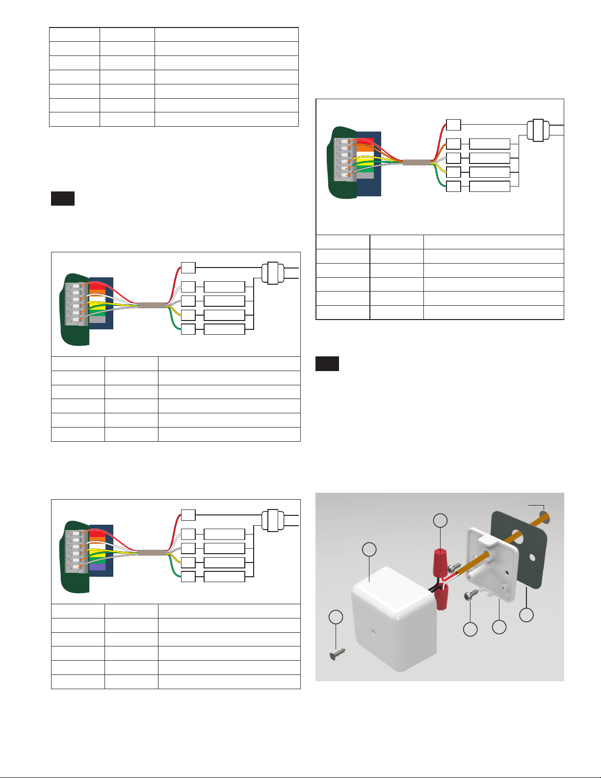
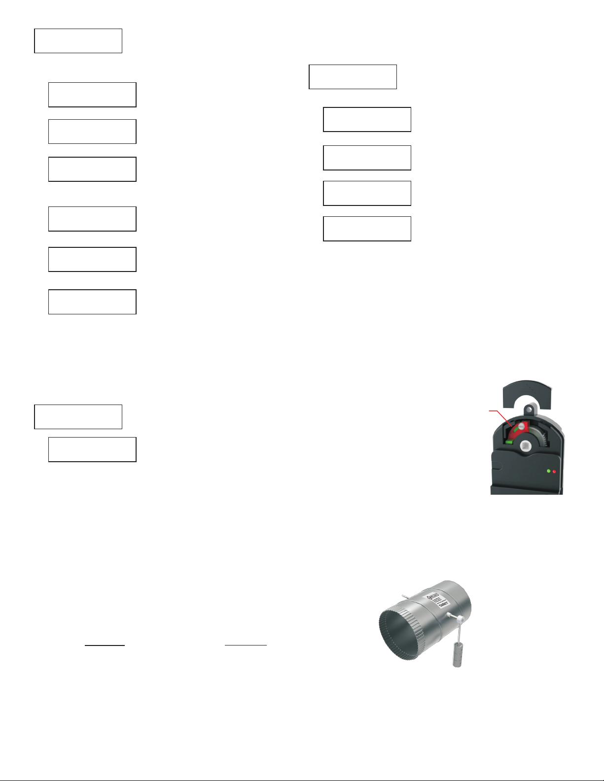
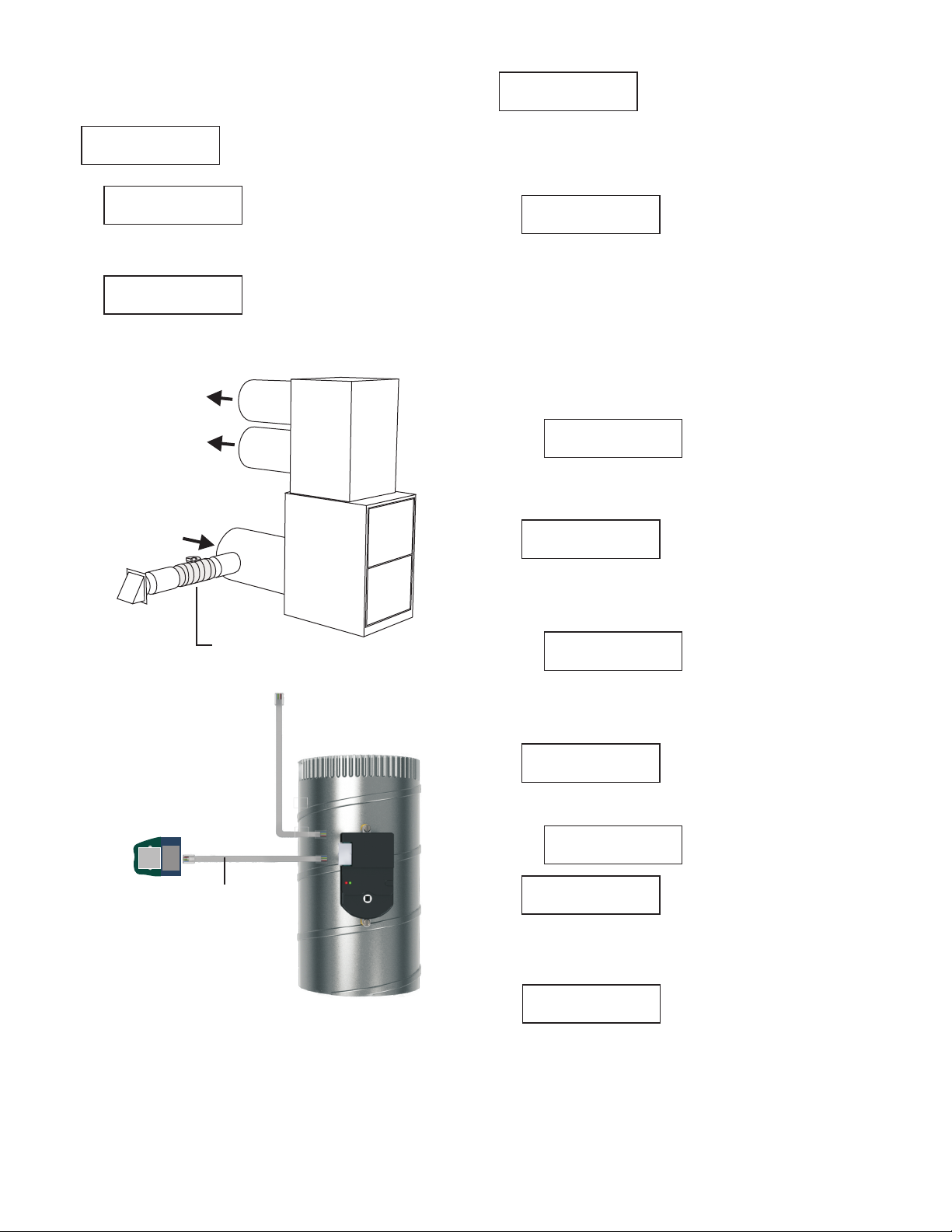
A damper can be used to bring outdoor air into the return to
maintain a healthy home. The equipment fan draws in the
outdoor air and mixes it with the return air from the home.
The panel attemps to fulfill the required fresh air during
heating and cooling calls. As the end of each hour
approaches, the panel will open the fresh air damper and
activate the indoor fan (G) if additional fresh air minutes are
required.
The PDMi3 allows the installer to directly set the minutes
per hour the fresh air damper is open or the PDMi3 can
calculate the required CFM of fresh air based on the area
of the home and the number of bedrooms.
Fresh air operation is factory set to Off.
If the contractor has calculated the CFM for fresh air and sized
the damper to operate for a number of minutes each hour, the
minutes can be directly entered.
The PDMi3 allows the installer to calculate the required CFM of
fresh air based on the area of the home and the number of
bedrooms. The calculated CFM is the CFM required if the fresh
air damper is continuously open and the indoor fan operating to
draw in fresh air.
The PDMi3 tutors the installer to set the area of the home in
square feet and the number of bedrooms. It then calculates and
displays the minimum amount of outdoor air required to meet the
requirement for the home. This is the amount required if the
indoor fan was running continuously.
If the fresh air intake is increased, the fresh air operation can
occur mostly during calls to minimize dis-comfort. The PDMi3 will
then display the number of minutes of fresh air operation required
each hour based on the minimum CFM and the selected CFM.
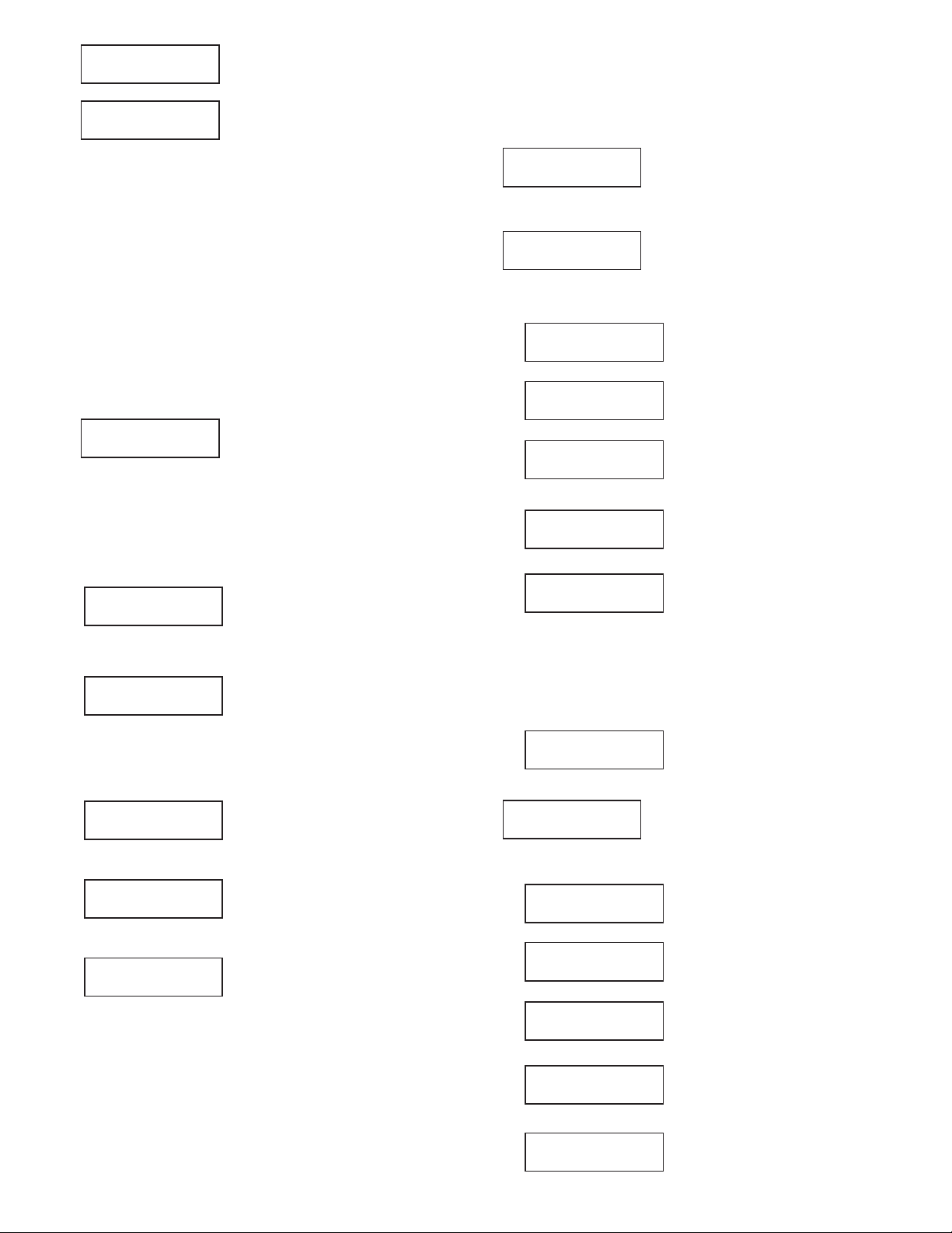
Fresh Air Control for Title24 and ASHRAE 62.2
Change or Set Fresh Air Operation
Direct Entry of Minutes per Hour of Fresh Air
PDMi3 Calculates Minutes per Hour of Fresh Air
Press Up or Down to set the area of
the home. Press NEXT to continue.
Press Yes to have the PDMi3 calculate
the fresh air requirements. Press No to
directly set the minutes per hour of fresh
air operation.continue.
Press Up or Down to set the
number of minutes the fresh air
damper and indoor fan must
operate each hour to meet the fresh
air requirements. Press NEXT to
continue.
Press Yes to enter the minutes of
fresh air operation required each
hour. Press No to select calculating
the CFM and minutes per hour.
Press Yes to change the Fresh Air
Option. Press no to continue to
another option.
Press Yes to turn the Fresh Air
Option On or No to turn it Off.
Press Up or Down to set the
bedrooms in the home. Press NEXT
to continue.
The PDMi3 shows the minimum CFM
required when the fresh air duct is
operating continuously.
Press Up or Down to adjust the fresh
air CFM. Increasing the CFM to 210
would lower the number of minutes
per hour of fresh air operation
allowing it to be accomplished during
calls. Press NEXT to continue.
The PDMi3 shows the number of
minutes of fresh air operation each
hour. Press Up or Down to adjust the
fresh air minutes each hour. Press
NEXT to continue to the next menu
selection.
Fresh Air Calc
Y/N
Fresh Air Enter
Min/Hr Y/N
Change Fresh Air
Option Y/N
Fresh Air Off
Y-On/N-Off
Area 2200
SqFt U/D/NEXT
Bedrooms 4
U/D/NEXT
Fresh Air 70
CFM U/D/NEXT
Fresh Air 20
Min/Hr U/D/NEXT
Fresh Air 20
Min/Hr U/D/NEXT
Fresh Air 210
CFM U/D/NEXT
Press Yes to select limiting upstaging
based on outdoor temperature.
Staging is controlled by the number of minutes heating or
cooling has been calling. The Timer monitors the continuous
call time and forces staging when the call time exceeds the
preset limits.
Staging can be disabled if the outdoor temperature exceeds
the preset limits.
Limit Staging Based on Outdoor Temperature
Press Yes to select timed upstaging.
Press Up or Down to set the number
of minutes of continuous call time
required to upstage to Stage2. Press
NEXT to continue.
Press Up or Down to set the number
of minutes of continuous call time
required to upstage to Stage3. Press
NEXT to continue to the next menu
selection.
Press Up or Down to set the outdoor
temperature to disable staging
heating. If the outdoor temperature is
above the limit, staging of heating is
disabled. Press NEXT to continue.
Press Up or Down to set the outdoor
temperature to disable staging
cooling. If the outdoor temperature
is below the limit, staging of cooling
is disabled. Press NEXT to continue
to the next menu selection.
Staging Based on Call Timer
Timed
UpStaging Y/N
Stage 2 20
Minutes U/D/NEXT
Stage 3 30
Minutes U/D/NEXT
Limit Staging
OD Temp Y/N
OD Temp Lmt 60
Heating U/D/NEXT
OD Temp Lmt 55
Cooling U/D/NEXT

Fresh air operation can be disabled if the outdoor temperature
exceeds the high and low temperature limits. A TS3 outdoor
temperature sensor is required.
Limit Fresh Air Based on Outdoor Temperature
Press Up or Down to set the low
outdoor temperature limit for fresh
air operation. Press NEXT to
continue.
Press Up or Down to set the high
outdoor temperature limit for fresh
air operation. Press NEXT to
continue.
Press Yes to set outdoor temperature
limits for fresh air operation or No to
continue to next option.
Limit Fresh Air
By ODTemp Y/N
Low ODTemp 30
Limit U/D/NEXT
High ODTemp 30
Limit U/D/NEXT
Change Advanced
Options Y/N
Auto Em Heat
Control Y/N
Auto Em Heat 35
OD Temp U/D/NEXT
Op System
Option Y/N
Op System 20
Minutes U/D/NEXT
Purge After
Call Y/N
Priority Heating
Equal Calls Y/N
Purge Time 60
Sec U/D/NEXT
Press Yes to select advanced options
such as purge, opposite system service,
heat or cooling priority, automatic
emergency heat control, moderate
weather staging inhibit and others. Press
No to continue to next menu selection.
Select automatic Emergency heat
operation when the outdoor
temperature drops below the
temperature set.
Press Yes to select opposite system
service. The panel normally services
heating or cooling calls based on the
number of calls from the zones. If
there are more heating calls than
cooling it will service heating and vice
versa.
Opposite System option forces it to
service the minority calls after it has
been calling for a period longer than
the set limit. Press No to continue.
Press Up or Down to set the
number of minutes the opposing
system must call before switching
to service it. Press NEXT to
continue.
Press Up or Down to set the
number of seconds the fan
operates at the end of a heating
or cooling call. Press NEXT to
continue.
Press Yes or No to select Purge.
Purge continues to operate the indoor
fan after a heating or cooling call to
recover heat or cold stored in the
mechanical system. Press NEXT to
continue.
This option determines whether a
heating or cooling call is activated
when an equal number of zones are
calling for heating and cooling. Press
No to display Heating or cooling.
Press Yes to select the system
displayed and continue.
13
FRESH
AIR
DAMPER
Zoning
Panel
25-foot Cable
provided with damper.
To optional
exhaust damper.
Fresh Air Damper
Model ProR80J-XX
Return air
Leaving air
Changing Advanced Options
Auto Em Heat
Control Y/N
When set to Yes, all heating calls are
treated as Em heat calls until the
Zone that called for Em heat calls for
non-Em heat or cooling.

14
Change Timing
Options Y/N
Min Run Time 2
Minutes U/D/Next
Min Off Time 2
Minutes U/D/Next
Press Up or Down to set the
number of minutes a heating or
cooling call must run. Press
NEXT to continue.
Press Up or Down to set the
number of minutes a heating or
cooling call must be off before
another call is started. Press
NEXT to continue.
Press Yes to change the minimum
run and off times or press No to
continue.
Display Data And
Settings Y/N
Start Panel Test
Y/N
Start Dmpr Test
Y/N
Start Cooling
Test Y/N
Cooling Stg1 On
DA Temp 56 Next
Start Htg Test
Y/N
Heating Stg1 On
DATemp 110 NEXT
Start Bypass
Test Y/N
All Dampers Open
Cooling On Next
Damper 1 Open
Clg On U/D/NEXT
Damper 1 100%
Clg On U/D/NEXT
Damper 2 Closed
Clg On U/D/NEXT
Damper 2 Closed
Clg On U/D/NEXT
All Dampers Open
NEXT
Damper 1 Closed
NEXT
Damper 2 Closed
NEXT
Press Yes to display all the option
settings, sensor data, call status, error
messages and much more. This option
only displays settings and data. No
setting can be changed. Press No to
continue.
Press Yes to start a test of damper
operation, cooling system and the
heating system.
Press Yes to start a test of the
dampers to insure they are opening
and closing.
Press Yes to start a test of the
cooling system to insure discharge
temperature is correct
Press Next to test stage2 cooling or
start a heating test (if only 1 cooling
stage).
Press Yes to start a test of the
heating system to insure discharge
temperature is correct.
Press Next to start a test stage2
heating to insure discharge
temperature is correct or return to
the main menu if only one stage of
heating is used.
Press Yes to start a bypass test. A
test will be started based on the type
of bypass being used.
Press Next to select which dampers
are open and closed.
Press the Up and Down keys to
open or close a damper. Press the
Next key to change the next damper.
To test various bypass settings, use
the Up and Down keys to set the
position of each zone damper. Fully
open is 100% and fully closed is 0%.
Press Next to set the next damper.
After setting the position of each
damper, press the Save key to have
the panel position the dampers.
Check the airflow in both calling
zones and non-calling zones to
insure the airflow is acceptable.
Press the Cancel key to cancel the
test and return to the main menu.
Press the Up and Down keys to
open or close a damper. Press the
Next key to change the next damper.
After setting the dampers to open
and close, press the Save key to
have the panel position the
dampers.
Adjust the barometric damper and
check that the airflow to the non-
calling zones is low enough.
Press Cancel to end the test and
return to the main menu.
All the dampers open and the fan is
activated. Check that you have air
from the registers in all zones. Press
Next to continue.
Damper1 closes. Check that there
is no air from the registers in Zone1.
Press Next to continue.
Damper1 opens and Damper2
closes. Check that there is no air
from the registers in Zone2. Press
Next to continue to test each zone
damper.
Testing the Installation
Bypass Testing
Bypass Testing with External Barometric Damper
Bypass Testing Modulating the
Non-Calling Zone Dampers

15
Restore Defaults
Y/N
Press Yes to restore the panel to the
factory settings. Press No to continue.
Save Options Now
Y/N
Save Selections
As Clone Y/N
Description For
Clone 1 NEXT
A
U/D/NEXT/SAVE
Press Yes to save the options and
settings selected. Press No to return to
the main menu.
Press Yes to save the options as a
new clone to be used later. Press
No to return to the main menu.
Press NEXT to enter the name for
Clone 1.
Press Up or Down to select the letter
or number. Press NEXT to go to the
next letter in the name. Press SAVE
to save the clone name.
Monitor HVAC
Performance Y/N
LAT 122 Prs 0.55
BP Pos 0% NEXT
Press Yes to display the leaving air
temperature, duct pressure and the
position of the non-calling zone
dampers when used for bypass.
Press No to continue.
Displays the leaving air
temperature and duct pressure (if
sensor installed). Bypass position
can be viewed by pressing the
Menu key. Press No to continue to
Show Zone Damper Status. The
date is automatically updated
every 5 seconds. Press Next to
return to the main menu.
Save Clone
Description Y/N
Press Yes to save the clone data
and the name. Press No to return to
the main menu.

26072 Merit Circle #110 / Laguna Hills, CA 92653
949-916-0945 Fax 949-458-8502 www.ProZone-US.com
Limited 5-Year Warranty
The 5-year warranty is limited to the repair or replacement of
defective product due to parts failure or defective workmanship.
ProZone
This manual suits for next models
3
Table of contents
Other Prozone Industrial Equipment manuals
Popular Industrial Equipment manuals by other brands

Siemens
Siemens 8MF1 Series operating instructions

Jäger
Jäger Z80-K440.21 S4 manual

Endress+Hauser
Endress+Hauser Hart Proline Promag P 500 Special Documentation

Otec
Otec ECO mini dry operating instructions

PCB Piezotronics
PCB Piezotronics 320C34 Installation and operating manual

ABB
ABB HT613266 Operation manual