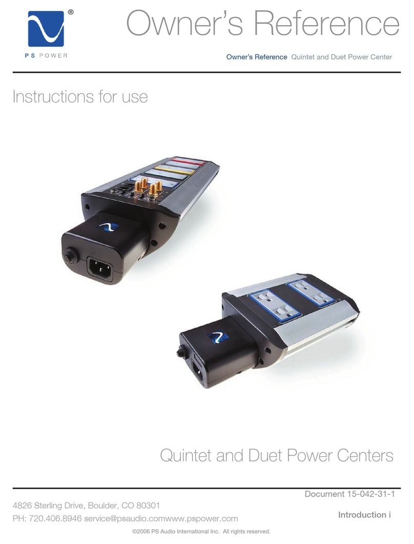
PS Audio Power Plant P300 Quick start guide

1
Power Port Upgrade Instructions for P300 and P600 Power Plants
Please read these instructions before attempting to install the new PS Audio Power Port AC
receptacles in your P300 or P600 Power Plant. These new receptacles replace the existing
hospital grade receptacles and are designed to improve the performance of your Power Plant.
Your kit contains the following:
• Power Ports
• New mounting hardware: 2 black screws (3 for P300) and two nuts for each Power Port
• Instruction manual
Tools required:
• One small and one medium Phillips screwdriver
• Large heavy duty pair of wire-cutters or tin snips (pliers will also work)
• P600 only – Allen wrench originally supplied for removing top cover
General Walk through
The replacement of the rear-mounted outlets is rather simple. Here are the basic steps you will
be taking:
1. Disconnect your Power Plant from its power supply.
2. Place unit in a well-lit workspace and obtain all necessary tools.
3. Remove the bottom cover of a P300, or the top cover of a P600.
4. Remove the existing hospital grade outlets and replace with a Power Port.
5. Replace the top or bottom cover.
6. You are done.
The procedure for replacing the hospital grade outlets with Power Ports, once inside the unit, is
very similar for each model. The differences per model are in gaining access to the inside of the
unit, and re-attaching the plugs back onto the rear panel.
Gaining access to inside the P300
Step One
Disconnect the Power Plant.
IMPORTANT! To correctly discharge the internal energy storage and prevent a potential shock
hazard, you must unplug the Power Plant while it is turned on and providing power for at least
one product. This will not damage the Power Plant or the connected device. However to ensure
that your equipment does not get damaged we recommend you use a simple load device such as
a table lamp for this step. (It will typically take less then 5 seconds for the unit to fully discharge.)
Once your Power Plant has cooled sufficiently to the touch, Place it in a well-lit place such as on
a table or open floor where you can have easy access and plenty of space to work on it. Make
sure you have all required tools available.

2
Step Two
Remove the bottom cover.
To remove the bottom cover of the P300, turn the unit upside down. Note the Phillips screws
along the outer edge of the bottom cover. Remove these screws. Place the screws in a cup or
safe area. Gently pull the bottom cover off of the P300. The bottom cover is used to secure the
internal oscillator board of the P300, so you may feel a small amount of resistance when you
attempt to remove the bottom cover. Try to remove the bottom cover without unseating this
internal PC board. Should the PC board come loose you must reinsert it back into its socket.
The board goes in only one way. The board components face the front panel of the P300.
Failure to replace the board properly will damage the P300. If in doubt please call PS Audio.
If your P300 is equipped with a fan kit, follow the two white wires attached to the bottom plate and
remove the white plug from the motherboard. Note that this plug attaches to the connector
labeled “J9.” Be sure to replace the plug into the J9 slot when reinstalling the fan.
Gaining access to inside the P600
Step One
Disconnect the Power Plant.
IMPORTANT! To correctly discharge the internal capacitive energy storage you must unplug the
Power Plant while it is turned on and providing power for at least one product. This will not
damage the Power Plant or the connected device. However to ensure that your equipment does
not get damaged we recommend you use a simple load device such as a table lamp for this step.
Once your Power Plant has cooled sufficiently to the touch, Place it in a well-lit place such as on
a table or open floor where you can have easy access and plenty of space to work on it. Make
sure you have all required tools.
Step Two
Remove the top cover.
Note: Your P600 top cover is made from a very high-grade aluminum and scratches very easily.
Use caution when removing and place on top of something soft like a towel to avoid scratching.
Using the original equipment supplied Allen wrench (7/64” size), remove all the Allen screws that
affix the top cover. Remove the top cover.
Once inside the Power Plant you are ready for the upgrade
**NOTE: You may remove the rear panel of the P300 to gain easier access to the
receptacles. This can be accomplished by removing the four screws (one on each corner)
that attach the plate to the sidewalls of the chassis. Replace the rear panel using the same
screws and in the same orientation. You CANNOT remove the rear panel for a P600.
Step One
Remove the existing hospital grade outlets.
To remove the existing hospital grade outlets, simply unscrew the Phillips screws on the back
panel that hold the outlet in place. You must, at the same time, hold the screw’s nut while
removing the screw. (For the P300 only, you will also need to remove the screws in between two
plugs of each outlet on the back panel.)
Physically remove all outlets from chassis without disconnecting any wires just yet!
3
Step Two
Remove the wires on one outlet at a time.
There are four wires connecting the outlet: black, white and two green*. Remove the black and
white wires, by loosening the side-mounted screws on the outlet. The wires will pull out easily.
The green wires are removed by unscrewing the green Phillips screw.
* The lower outlet on the P300 has more green wires and requires slightly different
instructions noted later in this document. This is not of concern until you are ready to mount the
replacement Power Port.
Step Three
Prepare the Power Port.
To prepare the Power Port, remove the silver mounting screw on each end of the Power Port.
Dispose of the screws. Remove the one silver U-shaped clip found at the bottom of the Power
Port (this is called a Tinnerman nut and is only needed for in-wall installation). Discard the
Tinnerman nut.
Step Four
Attach the wires to the Power Port. It is VERY IMPORTANT that all wires are securely mounted.
Loose wires will result with an intermittent connection that may cause severe damage to the
Power Plant and may also pose a potential shock hazard by connecting live voltage to the
chassis.
Loosen the silver colored side-mounted screw on the Power Port. Insert the white wire in the rear
hole. Tighten the silver screw on the side. Tug on the wire and make sure it is firmly help in
place. Repeat the same process with the black wire, and the side mounted gold colored screws.
The green ground wires are run in series (“Daisy Chained”) through each receptacle. Both green
wires have a lug attached to them. If the lug is an open spade type connector, simply push the
lug onto the green screw on the Power Port and tighten the green screw until the lug and green
wire are held firmly in place. If the green wire lug is a ring type and not open on one end, then
you will need to first remove the green screw completely from the Power Port and place the screw
through the ring terminal and then tighten the green screw.
Make sure each receptacle has two green ground wires attached to its ground post.
P300 attach the Power Ports
Step One
Snip the corners of the top Power Port.
On many versions of the P300, the top “ears” of the Power Port will collide with the rear panel
binding post and the sidewall. It will be necessary to “snip” the ear off in order to fit. Look closely
at the ear and note that there is a scored marking on the ear. Take your wire cutter or tin snips*,
and simply cut the ear off at the scored marking.
* (If you do not have access to snips or cutters that are capable of cutting this metal, then you
may also use a pair of pliers or dikes to bend the metal back and forth along the scored line until
fatigue causes it to break.)
Step Two
Using the new hardware provided in the kit, replace the screw and nut that hold the Power Port in
place. (P300 only – you will also need to re-insert the screws found between the plugs)

4
Attach the two ground tabs (two green wires each) to the mounting screw of the bottom outlet.
Use the screw that is nearest the ground terminal. The tabs go on after the Power Port and
mounting screw is inserted and right before the nut. This completes the ground for the CATV
filter and chassis.
Tighten the screws with your Phillips screwdriver while holding the inside nut in place with your
finger. The nut has a locking star washer that will dig into when tightened allowing you to easily
hold it in place with just your fingers.
Step Three
Check your work.
Make sure that the white wire is going to the side of the Power Port with the silver colored screw.
The black wire goes to the gold colored screw side. The green wires attach to the bottom corner
of the Power Port on a green screw.
Step Four
Replace the bottom cover, making certain that the oscillator PC board is firmly in place and the
fan is plugged into J9. You are done.
P600 attach the Power Port.
It is easiest if you attach outlets one and two first, four next, and three last, looking at the rear
panel from behind the Power Plant, reading left to right. Using this convention, you will find that
the most difficult outlet to attach is number four, behind the large transformer. If you do this one
before attaching the third one (from the left as you face the rear panel) you will find more room for
your fingers.
Step Two
Using the new hardware provided in the kit, replace the screw and nut that hold the Power Port in
place.
Tighten the screws with your Phillips screwdriver while holding the inside nut in place with your
finger. The nut has a locking star washer that will dig into when tightened allowing you to easily
hold it in place with just your fingers.
Step Three
Check your work.
Make sure that the white wire is going to the side of the Power Port with the silver colored screw.
The black wire goes to the gold colored screw side. The green wires attach to the bottom corner
of the Power Port on a green screw.
Make sure the fourth Power Port has its second green wire attached to the green binding post on
the rear panel.
Step Four
Replace the top cover. Congratulations, you are done. Your Power Plant is now equipped with
the latest power delivery technology available!!
PS Audio International, 3050 Broadway, Suite 201, Boulder Colorado, 80304 USA. 720-406-8946.
WWW.PSAUDIO.COM
Made in USA
Other manuals for Power Plant P300
4
This manual suits for next models
1
Table of contents
Other PS Audio Power Supply manuals

PS Audio
PS Audio Dectet Power Center Quick start guide

PS Audio
PS Audio Power Plant P1000 Manual

PS Audio
PS Audio Power Plant Premier Quick start guide

PS Audio
PS Audio UPC-200 Quick start guide

PS Audio
PS Audio Power Plant P300 User manual

PS Audio
PS Audio UPC-HB Power Center Quick start guide

PS Audio
PS Audio Quintessence Power Center Quick start guide

PS Audio
PS Audio Power Plant P300 User manual

PS Audio
PS Audio Stellar PowerPlant 3 Quick start guide

PS Audio
PS Audio Analog HCPS User manual