PS TMB PS 045 Instruction Manual

Citroen Berlingo I (1996 – 2008)
Peugeot Partner I (1996 – 2008)
MONTÁŽNÍ A UŽIVATELSKÝ NÁVOD
MONTAGE UND BEDIENUNGSANLEITUNG
USER’S GUIDE INSTALLATION INSTRUCTIONS
TMB PS 045
SPOJOVACÍ - TAŽNÉ ZAŘÍZENÍ
VERBINDUNGS – ANHÄNGERKUPPLUNG
TRAILER COUPLING DEVICE
pro automobily
Für Personenkraftwagen
for passenger cars
Citroen Berlingo, Peugeot Partner
s přišroubovaným tažným ramenem
mit angeschraubtem Kugelhals
with bolt-on towarm
e8 * 94/20 * 0082
© 2.12.2008

2
Seznam dílůtažného zařízení:
Verzeichnis der Teile der Anhängerkupplung:
List of components:
Název dílu KusůPozice
Bezeichnung des Teils, Name of the part Stück, Quantity Position, Positon
Nosník úplný (s identifikačním štítkem)
Träger vollständig (mit Identifikationsschild)
Beam assembly (with ID plate) 1 1
Konzola L+P (Konzole L+R, Side arm L+R) 1+1 3+2
Tažné rameno (Kugelhals, Towarm) 1 4
Šroub (Schraube, Bolt) M12 x 65 2 5
Matice (Mutter, Nut) M12 2 6
Podložka (Unterlegscheibe, Washer) ø13 2 7
Šroub (Schraube, Bolt) M8 x 25 2 8
Matice (Mutter, Nut) M8 2 9
Podložka (Unterlegscheibe, Washer) ø8,4 2 10
Podložka (Unterlegscheibe, Washer) ø8,4 2 11
Šroub (Schraube, Bolt) M10 x 80 4 12
Rozpěrka (Distanzrohr, Spacer) 4 13
Matice (Mutter, Nut) M10 8 14
Podložka (Unterlegscheibe, Washer) 10 x 40 4 15
Podložka (Unterlegscheibe, Washer) ø10,5 8 16
Šroub (Schraube, Bolt) M10 x 30 4 17
Držák zásuvky (Steckdosenhalter, Plug box holder) 1 18
Krytka kul. čepu (Kugelbolzendeckel, Cover of the ball) 1 19
Samolepící štítek (Selbstklebeetikette,
Self-adhesive sticker) „70 kg“ 1 -

3
TAŽNÉ ZAŘÍZENÍ
TMB PS 045
Upozornění
Díl „tažné zařízení“ , TMB PS 045 – je určen pouze k odborné montáži
v autorizovaném servisu. Montáž vyžaduje použití speciálního nářadí, dílenských
příruček a proto nesmí být díl „ tažné zařízení“ prodán konečnému uživateli
v nenamontovaném stavu.
Tažné zařízení je vyrobeno podle schválené dokumentace a odpovídá
homologaci e8*94/20*0082.
Všeobecné údaje
Konstrukce tažného zařízení odpovídá všem mezinárodním předpisům.
Zařízení prošlo pevnostními zkouškami dle evropské směrnice 94/20ES,
Tažné rameno je opatřeno kulovým čepem o průměru 50 mm dle ISO 3853.
Elektrická instalace pro tažné zařízení není součástí dodávky.
Při montáži je nutné vyříznout otvor na spodní stranězadního nárazníku.
Technické parametry
Tažné zařízení je konstruováno pro:
maximální povolenou hmotnost tažného vozidla 1 990 kg
maximální hmotnost brzděného přívěsu 1 100 kg
maximální hmotnost nebrzděného přívěsu 750 kg.
max. svislé statické zatížení na kulový čep 70 kg.
(Platí omezení hmotnosti přívěsu dle technického průkazu vozidla.)
DC– Wert (vztažná síla) – 7 kN.
C
T
CT
gDC
g– tíhové zrychlení (g = 9,81 ms-2)
T– hmotnost tažného vozidla [t]
C– hmotnost přívěsu [t]
Celková hmotnost tažného zařízení – 13,5 kg
Rozměry 1 020 x 660 x 275 mm.

4
Seznam speciálního nářadí :
Pila pro vyříznutí otvoru do nárazníku
Momentový klíč
Postup montáže
- Ustavte vozidlo na ramena dílenského zvedáku.
- Demontujte zadní světla a obložení zav. prostoru.
- Demontujte zadní nárazník (lapače nečistot jsou-li na vozidle)
- Demontujte příčník zadního nárazníku.
- Demontujte držák rezervního kola.
Vystřižení otvoru do zadního nárazníku
- Demontovaný zadní nárazník položte na měkkou plstěnou podložku.
- Na vnítřní straněnárazníku naměřte jeho střed a nakresletete rysku.
- Vystřihněte papírovou šablonu přiloženou v návodu.
- Přiložte papírovou šablonu na vnitřní stranu nárazníku, dle popisu na šabloněa
obkreslete tvar vystřižení.
- Podle vzníklé rysky vystřihněte (vyřízněte) vhodným nástrojem otvor pro tažné
rameno a držák zásuvky (pozor na poškození laku nárazníku). Otvor začistěte.
- Takto připravený zadní nárazník odložte na vhodné místo.
Montáž tažného zařízení na vozidlo
- Strhněte záslepky otvorůpro uchycení tažného zařízení na zadních podélnících
(oběstrany vozu). V případěpotřeby odstraňte části plastizolu uvnitřpodélníků.
- Konzole L+P (3+2) přišroubujte pomocí čtyřšroubůM10 x 80 (12),vymezovacích
trubiček (13), podložek (15 + 16) a matic M 10 (14) k podvozku vozidla.
- Nosník (1) přišroubujte ke konzolám (3+2) pomocí čtyřšroubůM10 x 30 (17),
podložek (16) a matic M10 (14). K zadnímu čelu přišroubujte nosník (1) pomocí
dvou šroubůM8 x 25 (8), podložek (10 + 11) a matic M8 (9).
- Šrouby M10 dotáhněte utahovacím momentem 65 Nm, šrouby M8 dotáhněte
utahovacím momentem 35 Nm.

5
Montáž tažného ramena
- Tažné rameno (4) přišroubujte pomocí šroubůM12 x 65 (5), podložek ø13 (7) a
matic M12 (6) mezi držáky tažného zařízení.
- Na levý držák tažného ramena pod matici (6) (blíže kulového čepu) vložte držák
zásuvky (18).
- Šrouby provlékněte otvorem tak, aby hlava šroubu byla na pravém držáku tažného
ramena (ve směru jízdy).
- Šrouby dotáhněte utahovacím momentem 80 Nm.-
- Pokračujte montáží elektrické instalace tažného zatížení na vozidlo.
- Po skončení montáže elektrické instalace namontujte zpět všechny demontované
díly a příslušné spoje utáhněte předepsanými utahovacími momenty.
- Na zadní nárazník nad tažné rameno nalepte samolepicí štítek “70 kg” (příslušné
místo před nalepením očistěte a odmastěte).
- Na kulový čep tažného zařízení nasaďte krytku (19).

6
ANHÄNGERKUPPLUNG
TMB PS 045
Hinweis
Das Teil „Anhängerkupplung“ , TMB PS 045 – ist ausschließlich zur
Fachmontage in einem autorisierten Service bestimmt. Die Montage erfordert
die Verwendung spezieller Werkzeuge und Werkstättenhandbücher. Deswegen darf
das Teil „Anhängerkupplung“ dem Endverbraucher nicht in unverbautem Zustand
verkauft werden.
Die Anhängerkupplung ist nach genehmigter Dokumentation gefertigt worden
und entspricht der Typengenehmigung e8*94/20*0082.
Allgemeine Angaben
Die Konstruktion der Anhängerkupplung entspricht allen tschechischen und
internationalen Vorschriften.
Die Einrichtung wurde Festigkeitsproben laut der europäischen Richtlinie
94/20/EG unterzogen.
Der Kugelhals ist mit einem Kugelbolzen mit einem Durchmesser von 50 mm laut
ISO 3853 versehen.
Die Elektroinstallation der Zugvorrichtung bildet keinen
Lieferungsbestandteil.
Bei der Montage ist eine Öffnung auf der Unterseite des Heckstoßfängers
auszuschneiden.
Technische Parameter
Die Anhängerkupplung ist konstruiert für:
- maximal erlaubtes Gewicht des Zugsfahrzeugs 1 990 Kg
- Maximalgewicht des gebremsten Anhängers 1 100 Kg
- Maximalgewicht des ungebremsten Anhängers 750 Kg
Die maximale senkrechte statische Belastung des Kugelbolzens beträgt 70 Kg
(Es gelten die Gewichtseinschränkungen des Anhängers laut
Fahrzeugszulassungsschein)
DC– Wert (Bezugskraft) – 7 kN.
C
T
CT
gDC
g– Lastbeschleunigung (g = 9,81 ms-2)
T– Gewicht des Zugfahrzeugs [t]
C– Anhängergewicht [t]
Gesamtgewicht der Anhängerkupplung – 13,5 kg
Maße 1 020 x 660 x 275 mm.

7
Verzeichnis Spezialwerkzeug:
Säge für das Ausschneiden einer Öffnung in den Stoßfänger
Drehmomentschlüssel
Montageablauf
- Setzen Sie das Fahrzeug auf die Arme eines Werkstättenhebers.
- Demontieren Sie die Heckleuchten und die Gepäckraumverkleidung
- Nehmen Sie den Heckstoßfänger (Schmutzfänger, soweit auf dem Fahrzeug
befindlich)
- Nehmen Sie den Querträger des Heckstoßfängers ab.
- Demontieren Sie die Ersatzradhalterung.
Ausschneiden der Öffnung in den Heckstoßfänger
- Der demontierte Heckstoßfänger ist auf eine weiche Filzunterlage zu legen.
- Messen Sie auf der Innenseite des Stoßfängers seine Mitte aus und zeichnen Sie
eine Strichmarke ein.
- Schneiden Sie die in der Anleitung beiliegende Papierschablone aus.
- Legen Sie die Papierschablone auf die Innenseite des Stoßfängers laut der
Beschreibung auf der Schablone und zeichnen Sie die Ausschnittform ab.
- Schneiden Sie mit einem geeigneten Werkzeug eine Öffnung für den Deichselarm
und den Steckdosenhalter nach der entstandenen Strichmarke aus. (Achtung auf
Lackbeschädigungen des Stoßfängers) Die Öffnung ist zu säubern.
- Legen sie den so vorbereiteten Stoßfänger auf einen geeigneten Platz beiseite.
Montage der Anhängerkupplung auf das Fahrzeug
- Reißen Sie die Verblendungen der Öffnungen für die Befestigung der
Anhängerkupplung auf den hinteren Längsseiten ab (beide Fahrzeugsseiten).
Entfernen Sie im Bedarfsfall Plastisolteile aus dem Innerern der Längsträger.
- Konzole L+R (3+2) befestigen Sie mittels 4 Schrauben M10x80 (12), der
Distanzröhre (13), der Unterlegscheiben (15 + 16) und M10 Muttern (14) zum
Fahrgestell.
- Den Träger (1) befestigen Sie zu den Konzolen (3 + 2) mittels 4 Schrauben
M10x30 (17), Unterlegscheiben (16), und M10 Muttern (14). Zu hinterer Stirn
verschrauben Sie den Träger (1) mittels 2 Schrauben M8x25 (8), Unterlegscheiben
(10 + 11) und M8 Muttern (9).
- M10 Schraube ziehen Sie durch Anzugsmoment 65 Nm und die M8 Schraube
ziehen Sie durch Anzugsmoment 35 Nm an.

8
Montage des Kugelhals
- Schrauben Sie den Kugelhals (4) mit Hilfe der Schrauben M12 x 65 (5), Unterlagen ø13
(7) und Muttern M12 (6) zwischen die Halter der Anhängerkupplung. Legen Sie auf den
linken Halter des Kugelhals unter die Mutter (6) (näher zum Kugelbolzen) den
Steckdosenhalter (18). Ziehen Sie die Schrauben durch die Öffnung so durch, dass der
Schraubenkopf auf dem rechten Kugelhals (in Fahrrichtung) aufliegt.
- Ziehen Sie die Schrauben mit einem Anziehmoment von 80 Nm nach.-
- Setzen Sie die Montage der Elektroinstallation der Zugbelastung auf das Fahrzeug fort.
- Bauen Sie nach Beendung der Montage der Elektroinstallation alle demontierten Teile
wieder auf und ziehen Sie sie mit den vorgeschriebenen Anziehmomenten nach.
Kleben Sie auf den Heckstoßfänger über dem Kugelhals das Selbstklebeetickett “70 kg”
(die zuständige Stelle ist vor dem Aufkleben zu reinigen und zu entfetten).
- Setzen Sie auf den Kugelbolzen der Anhängerkupplung den Deckel auf (19).

9
COUPLING DEVICE
TMB PS 045
Important:
The part called „COUPLING DEVICE“ type TMB PS 045 – can be mounted only by an
authorized service station.The intallation requires special tools and workshop manuals and
for this reason the part „COUPLING DEVICE“ is not allowed to be sold to any enduser
free without installing.
The coupling device is made according to approved documentation and complies with
the homologation e8*94/20*0082.
General data
The design of the coupling device complies with all international standards
The coupling device passed all structure tests as stipulated in 94/20/EC,
The towarm has a ball pivot ø 50mm ISO 3853.
Electrical wiring is not included in this set
For mounting it is necessary to cut a hole at the bottom of the rear fender.
Technical data and parameters
The device is designed for:
total permitted weight of the towing vehicle 1 990 kg
braked trailers - maximum towed load 1 100 kg
unbraked trailer maximum towed load 750 kg
max. nose static weight on the ball pivot 70 kg
Mind the limits of the tow load in the registration certificate
DC– reference dynamic force 7 kN.
C
T
CT
gDC
g– gravitational acceleration (g = 9,81 ms-2)
T– towing car weight [t]
C– trailer’s weight [t]
Total weight of the coupling device – 13,5 kg
Dimensions 1 020 x 660 x 275 mm.
List of special tools and gadgets:
Suitable cutter for making an opening in the rear buffer
Torque wrench

10
Installing procedure
- Position the car on the garage jack’s arms.
- Dismount the tail lamps and the boot’s padding.
- Dismount the rear bumper ( and plastic mudguards if present).
- Dismount the crossbeam of the rear bumper.
- Dismount the stepney holder.
Cutting an opening in the back bumper:
- Dismounted back bumper is placed on a soft pad .
- Measure and score the center of the bumper on the bottom side.
- Cut out a paper template enclosed in the manual.
- Place the paper template on the internal side of the bumper as drawn on the template and
mark the shape.
- Cut out an opening for the towbar and plugbox holder in the bumper by a suitable tool
(beware of scratching the outer surface) and clean the edge of the hole.
-Put off the prepared bumper on a suitable place.
Mounting the equipment onto the car :
-Take out the blinds from the pre-bored holes in the sills on both sides of the car
underbody. If necessary, clean the interior of the holes from the deposits of plastic
protection.
- Screw up the side arms Left (3) + Right (2) with four bolts M10 x 80 (12), spacers (13),
washers (15+16) and nuts M10 (14) onto the underbody.
- Screw up the beam (1) to the side arms (3+2) with four bolts M10 x 30 (17), washers (16)
and nuts M10 (14). To the rear wall screw up the beam (1) with two bolts M8 x 25 (8),
washers (10+11) and nuts M8 (9).
- Tighten the bolts M10 by torque 65 Nm, the bolts M8 by torque 35 Nm.
Mounting the towarm
- The towarm (4) is fixed by the bolts M12 x 65 (5), washers ø13 (7) and nuts M12 (6)
between the brackets of the coupling device.
- Fasten the plugbox holder (18) onto the left holder of the towarm under the nut (6) (more
closely to the ball pivot).
- Put the bolts into the holes so that their heads remain on the right bracket (if looking
ahead);
- Tighten the bolts by the prescribed torque : 80 Nm.-
- Further step is the installation of electric wiring.
- After installing the cable harness remount back all dismantled parts and tighten the
appropriate joints by the respective torques.
- Put a self-adhesive sticker “70 kg” on the back bumper- above the towarm (clean and
degrease the appropriate place for the sticker).
- Place a lid onto the ball pivot of the towarm (19).

11
12
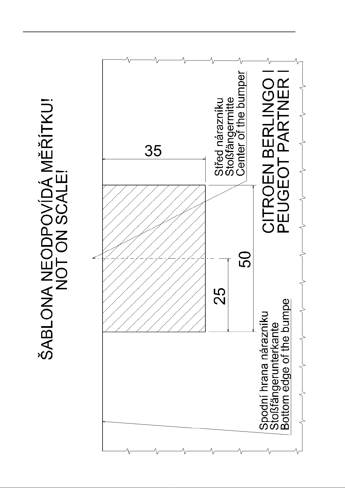
Šablona Schablone Template

13
Upozornění pro zákazníka
- Dotažení šroubů(5) upevňujících tažné rameno (4) kontrolujte pravidelněpo
ujetí cca 1000 km!
- Kulový čep občas namažte vhodným mazacím tukem.
- Po připojení přívěsu zasuňte zástrčku (od přívěsu) do zásuvky tažného zařízení a
zkontrolujte funkci světel na přívěsu.
- Veškeré změny a úpravy tažného zařízení jsou nepřípustné.
- Při používání tažného zařízení dodržujte pokyny uvedené v tomto návodu.
- Výrobce na sebe nebere zodpovědnost za škody způsobené chybněnamontovaným
tažným ramenem, jeho přetěžováním nebo poškozením při havárii vozidla.
- Tažné zařízení nesmí být provozováno je-li poškozeno nebo je neúplné.
- Není-li připojen přívěsný vozík k tažnému zařízení, musí být kulový čep chráněn
krytkou!
- Tažné rameno (pokud ho budete demontovat) uložte a zajistěte v zavazadlovém
prostoru tak, aby při náhlém zabrždění nemohlo ohrozit bezpečnost cestujících a
způsobit poškození zavazadlového prostoru. Na kulový čep tažného ramena nasaďte
krytku.
- Po ujetí prvních asi 500 km s přívěsem je nutné zkontrolovat dotažení upínacích
šroubůnosníku k podvozku vozidla a dotažení tažného ramena a případněje
dotáhnout předepsanými utahovacími momenty! Tuto kontrolu Vám doporučujeme
provést v nejbližším autorizovaném servisu.
Hinweis für den Kunden
- Kontrollieren Sie regelmäßig die Nachspannung der den Kugelhals (4) befestigenden
Schrauben (5) nach Zurücklegen von cca 1000 km!
- Schmieren Sie den Kugelbolzen hin und wieder mit einem geeigneten Schmierfett
ein.
- Schieben Sie nach Anhängeranschluss den Stecker (des Anhängers) in die Steckdose
der Anhängerkupplung und überprüfen Sie die Funktionstüchtigkeit der Lichter auf
dem Anhänger.
- Sämtliche Änderungen und Modifizierungen der Anhängerkupplung sind
unzulässig.
- Halten Sie bei der Verwendung der Anhängerkupplung die in dieser Anleitung
enthaltenen Anweisungen ein.
- Der Hersteller nimmt keinerlei Verantwort für Schäden auf sich, die durch eine
fehlerhaft angebaute Anhängerkupplung verursacht wurden, ihre Überbelastung oder
die Beschädigung beim Fahrzeugsunfall.
- Die Anhängerkupplung darf nicht betrieben werden, falls sie beschädigt oder
unvollständig ist.
- Falls kein Anhänger an die Anhängerkupplung angeschlossen ist, muss der
Kugelbolzen mit einer Haube geschützt werden!

14
- Der Kugelhals (falls Sie ihn anbauen werden) ist im Gepäckraum so abzulegen und
so zu sichern, dass er beim plötzlichen Bremsen die Sicherheit der Reisenden nicht
gefährdet und den Gepäckraum nicht beschädigt. Setzen Sie auf den Kugelbolzen des
Kugelhals eine Haube auf.
- Nach Zurücklegen der ersten ungefähr 500 km mit Anhänger ist die Anzugskraft
der Spannschrauben des Trägers an das Fahrgestell des Fahrzeugs und die
Nachspannung des Kugelhals zu überprüfen und gegebenenfalls mit den
vorgeschriebenen Anziehmomenten nachzuziehen! Wir empfehlen diese Kontrolle im
nächstgelegenen autorisierten Service vorzunehmen.
Notice to the customers
- Tightening of the bolts (5) fixing the towarm (4) must be checked regularly after
each 1000 km!
- The ball of the towarm should be occasionally cleaned and greased by a suitable
lubricant.
- Check the function of all lights on the trailer after coupling the trailer and pluging
the trailer to the plugbox on the towing vehicle.
- Any alternations of the towing equipment are not allowed.
- Follow the instructions of this guide while using the coupling device.
-The producer cannot take over any responsibility for any damage resulting from
improper installation of the towarm, its overloading or a crash of the car. – The
coupling device cannot be used if damaged or incomplete.
- In case of the trailer not being coupled with the car, the ball pivot must be
protected by a plastic cover!
- The towarm (in case it is removed from the brackets) should be stored properly in in
boot to prevent damgage to the car or any injury of the passangers at sudden braking.
The ball pivot shoult be covered by its plastic cover.
- After running the first about 500 km with a trailer it is necessary to re-tighten the
bolts fixing the crossbeam to the car underbody and the towarm with the prescribed
torques! We recoment to have this check done in your nearest authorized service
station.

15
Záruční list
Výrobce tažného zařízení poskytuje záruku na konstrukci, použitý materiál, výrobní
provedení a funkci dodaného tažného zařízení 24 měsícůod data prodeje.
Reklamaci výrobku v zákonné lhůtěuplatní kupující u prodávajícího. Oprávněnost
reklamace posoudí zástupce prodávajícího spolu se zástupcem výrobce v souladu
s platnými předpisy.
Podmínkou platnosti záruky je, aby tažné zařízení bylo používáno pouze k účelům, ke
kterým je určeno.
Kupující je povinen prověřit stav zboží při jeho převzetí. V případěpoškození zboží,
nedodání části tažného zařízení apod. je kupující povinen tuto skutečnost neprodleněohlásit
prodávajícímu a to bez zbytečného odkladu po převzetí zboží.
Všechny součásti a příslušenství tažného zařízení musí být před odbornou montáží,
zkontrolovány ve vztahu k jejich kompaktibilitěna odpovídající typ vozidla. Tažná
zařízení, smí být použita pouze na výrobcem uvedený typ vozidla. V případěneodborné
montáže či montáže tažného zařízení na typ vozidla, pro který není tažné zařízení určeno,
neodpovídá výrobce za případné poškození tažného zařízení, způsobené vadnou montáží či
jeho nesprávným použitím.
Prodávající odpovídá za vady, které mělo tažné zařízení při jeho převzetí kupujícím.
Záruka se nevztahuje na škody mající původ v běžném opotřebení, v přetěžování a
neodborném používáním tažného zařízení, dále pokud není užíváno v souladu s pokyny
uvednými v návodu k obsluze. Záruka se dále nevztahuje na škody způsobené živelnými
vlivy. Prodávající rovněž neodpovídá za škodu v případě, kdy bylo tažné zařízení změněno
či jinak upraveno.
Záruka zaniká, bylo-li tažné zařízení poškozeno havárií (kroměhavárie vyvolané
samotným tažným zařízením) nebo zásahy do jeho mechanismu a konstrukce.

16
Garantieinformationen und Bedingungen
Der Hersteller der Anhängerkupplung gewährt auf Konstruktion, verwendetes Material,
Produktionsausführung und Funktion der gelieferten Anhängerkupplung eine Garantie von
24 Monaten ab Verkaufsdatum.
Die Reklamation des Produkts in der gesetzlichen Frist macht der Käufer beim Verkäufer
geltend. Die Berechtigung der Reklamation beurteilt ein Vertreter des Verkäufers
zusammen mit einem Vertreter des Herstellers entsprechend der gültigen Vorschriften.
Bedingung für die Gültigkeit der Garantie ist, dass die Anhängerkupplung zum für sie
bestimmten Zweck angewendet wurde.
Der Käufer ist verpflichtet, den Zustand der Ware bei Übernahme zu überprüfen. Bei
Beschädigung der Ware, fehlendem Teil der Anhängerkupplung, u.ä. ist der Käufer
verpflichtet, diese Tatsache unverzüglich dem Verkäufer zu melden, dies ohne unnötigen
Verzug nach Warenübernahme.
Alle Teile und das Zubehör der Anhängerkupplung muss vor der fachgerechten Montage in
Beziehung zur Kompatibilität für den entsprechenden Fahrzeugtyp kontrolliert werden.
Anhängerkupplungen dürfen nur am vom Hersteller angeführten Fahrzeugtyp benutzt
werden. Bei nicht fachgerechter Montage oder Montage der Anhängerkupplung an einen
Fahrzeugtyp, für welchen sie nicht bestimmt ist, haftet der Hersteller nicht für eventuelle
Beschädigungen der Anhängerkupplung, verursacht durch fehlerhafte Montage oder falsche
Benutzung.
Der Verkäufer haftet für Mängel, welche die Anhängerkupplung bei Übernahme durch den
Käufer hatte.
Die Garantie bezieht sich nicht auf Schäden, die ihre Ursache in normalem Verschleiß,
Überlastung und nicht fachgerechter Benutzung der Anhängerkupplung haben, weiter wenn
sie nicht gemäß der Anweisungen in der Gebrauchsanleitung benutzt wurde. Die Garantie
bezieht sich weiter nicht auf durch Naturkatastrophen verursachte Schäden. Der Verkäufer
haftet ebenfalls nicht für Schaden, wenn die Anhängerkupplung geändert oder angepasst
wurde.
Die Garantie erlischt, wenn die Anhängerkupplung durch einen Unfall beschädigt wurde
(außer einem Unfall, hervorgerufen durch die Anhängerkupplung) oder bei Eingriff in ihren
Mechanismus und Konstruktion.

17
Guarantee information and conditions
The manufacturer of the towing coupling gives the guarantee for the construction, used
material, manufacturing execution and function of the supplied towing coupling for 24
months from the date of sale.
The complaints are to be presented by the buyer to the selling organization within the legal
period. The rightfulness of the complaint will be judged by a representative of the selling
organization together with a representative of the manufacturer in accordance with valid
regulations.
The prerequisite of validity of the guarantee is that the towing coupling has to be used only
for those purposes for which it is designed.
The buyer shall examine the condition of the goods at their reception. In case of any
damage of the goods or failure to deliver any part of the towing coupling the buyer shall
report such fact immediately to the selling organization without unnecessary delay after the
reception of the goods.
All parts and accessories of the towing coupling must be checked before professional fitting
with regard to their compatibility with the respective type of vehicle. The towing couplings
may be used only for the vehicle type stated by the manufacturer. In case of incompetent
fitting or fitting of the towing coupling on a type of vehicle for which the towing coupling
is not intended, the manufacturer shall not be responsible for any damage of the towing
coupling caused by defective fitting or its incorrect use.
The selling organization is responsible for defects the towing coupling had at its reception
by the buyer.
The guarantee does not cover any damages resulting from common wear and tear,
overloading and unprofessional use, as well as damages caused by non-compliance with the
instructions stated in the operating manual. The guarantee does not cover any damages due
to natural disasters. The selling organization is not responsible for any damage in the case
when the towing coupling was modified or otherwise altered.
The guarantee also becomes void if the towing coupling has been damaged due to an
accident (except accidents caused by the towing coupling itself) or by tampering with its
mechanism and construction.

18

19

20
Záruční list/ Garantieschein/ Certificate of guarantee
Výrobní číslo: .......................................................
Produktionsnummer:
Production No:
Datum výroby: .......................................................
Produktoinsdatum:
Date of production:
Výstupní kontrola výrobce: .......................................................
Ausgangskontrolle des Herstellers:
Final inspection of the manufacturer:
Datum prodeje: .......................................................
Verkaufsdatum:
Date of sale:
Prodávající: ...........................................................
Verkäufer: (Razítko a podpis prodávajícího)
Seller: (Stempel und Unterschrift des Verkäufers)
(Stamp and signature of the seller)
Výrobce: Manufacturer: Hersteller:
PROF SVAR s.r.o., Přestavlcká 1474, CZ - 295 01 Mnichovo Hradiště,
LDPE
4
Table of contents
Other PS Automobile Accessories manuals


