PS TMB PS 089 Mounting instructions

1
ŠKODA Rapid (2012 →)
SEAT Toledo (2012 →)
MONTÁŽNÍ A UŽIVATELSKÝ NÁVOD
MONTAGE UND BEDIENUNGSANLEITUNG
INSTALLATION INSTRUCTIONS AND USER’S
GUIDE
TMB PS 089
SPOJOVACÍ - TAŽNÉ ZAŘÍZENÍ
pro automobily
für Personenkraftwagen
for passenger cars
ŠKODA Rapid, SEAT Toledo
s odnímatelným tažným ramenem
mit demontierbarem Kugelhals
with removable tow arm
E8 55R-01 55671
© 20.02.2013

2
Seznam dílů, Verzeichnis der Teile, List of components:
Název dílu KusůPozice
Bezeichnung des Teils, Name of the part Stück, Quantity Position,
Positon
Krytka up. pouzdra (Verschlussdeckel, Cover of
clamping collet) 1 A
Tažné rameno (Kugelhals, Towarm) 1 B
Nosník (Träger , Beam ) 1 D
Krytka kul. čepu (Kugelbolzendeckel, Cover of the ball) 1 F
Šroub (Schraube, Bolt) M10 x 35 4 G
Držák zásuvky (Steckdosenhalter, Plug box holder) 1 H
Klíč(Schlüssel, Lock key) 2 I

3
TAŽNÉ ZAŘÍZENÍ
TMB PS 089
Upozornění
Díl „tažné zařízení“ , TMB PS 089 doporučujeme montovat v autorizovaném
servisu. Montáž vyžaduje použití speciálního nářadí a dílenských příruček.
Tažné zařízení je vyrobeno podle schválené dokumentace a odpovídá
homologaci E8 55R-01 55671.
Všeobecné údaje
Konstrukce tažného zařízení odpovídá všem mezinárodním předpisům.
Zařízení prošlo pevnostními zkouškami dle evropského předpisu EHK 55,
Tažné rameno je opatřeno kulovým čepem o průměru 50 mm dle ISO 3853.
Elektrická instalace pro tažné zařízení není součástí dodávky.
Technické parametry
Tažné zařízení je konstruováno pro:
maximální hmotnost brzděného přívěsu 1 400 kg
maximální hmotnost nebrzděného přívěsu 640 kg
max. svislé statické zatížení na kulový čep 75 kg
Platí omezení hmotnosti přívěsu dle technického průkazu vozidla!
DC– Wert (vztažná síla) – 8,0 kN.
C
T
CT
gDC
g– tíhové zrychlení (g = 9,81 ms-2)
T– hmotnost tažného vozidla [t]
C– hmotnost přívěsu [t]
Celková hmotnost tažného zařízení – 15,6 kg
Rozměry 1 053 x 651 x 266 mm.
Seznam speciálního nářadí :
Pila pro vyříznutí otvoru do nárazníku
Momentový klíč

4
Postup montáže
- Ustavte vozidlo na ramena dílenského zvedáku.
- Demontujte zadní světla a obložení zav. prostoru.
- Demontujte zadní nárazník (lapače nečistot jsou-li na vozidle)
- Demontujte příčník zadního nárazníku, matice namontujte zpět.
Vystřižení otvoru do zadního nárazníku
- Demontovaný zadní nárazník položte na měkkou plstěnou podložku.
- Dle předlisovaného označení vystřihněte (vyřízněte) vhodným nástrojem otvor
pro tažné rameno a držák zásuvky. Otvor začistěte.
- Takto připravený zadní nárazník odložte na vhodné místo.
Montáž tažného zařízení na vozidlo
- Strhněte záslepky otvorůpro uchycení tažného zařízení na zadních podélnících
(oběstrany vozu). V případěpotřeby odstraňte části plastizolu uvnitřpodélníků.
- Tažné zařízení nasuňte podélnými nosníky do otvorůna zadním čele vozu a
ustavte ho do správné polohy.
- Nosníky přišroubujte pomocí čtyřšroubůM10 x 35 (G) k podvozku vozidla a
šrouby (střídavě) na obou stranách dotáhněte utahovacím momentem 70 Nm.
- Pokračujte montáží elektrické instalace tažného zařízení na vozidlo.
- Po skončení montáže elektrické instalace namontujte zpět všechny demontované
díly a příslušné spoje utáhněte předepsanými utahovacími momenty.

5
ANHÄNGERKUPPLUNG
TMB PS 089
Hinweis
Das Teil „Anhängerkupplung“, TMB PS 089 empfehlen wir, in einem
autorisierten Service montieren zu lassen . Die Montage erfordert die
Verwendung spezieller Werkzeuge und Werkstättenhandbücher.
Die Anhängerkupplung ist nach genehmigter Dokumentation gefertigt worden
und entspricht der Typengenehmigung E8 55R-01 55671.
Allgemeine Angaben
Die Konstruktion der Anhängerkupplung entspricht allen tschechischen und
internationalen Vorschriften. Die Vorrichtung wurde auf Festigkeit laut der
europäischen Reglement ECE 55 geprüft. Der Kugelhals ist mit einem
Kugelbolzen mit einem Durchmesser von 50 mm laut ISO 3853 versehen.
Die Elektroinstallation der Zugvorrichtung bildet keinen
Lieferungsbestandteil.
Technische Parameter
Die Anhängerkupplung ist konstruiert für:
- Maximalgewicht des gebremsten Anhängers 1 400 Kg
- Maximalgewicht des ungebremsten Anhängers 640 Kg
Die maximale senkrechte statische Belastung des Kugelbolzens beträgt 75 Kg
Es gelten die Gewichtseinschränkungen des Anhängers laut
Fahrzeugszulassungsschein!
DC– Wert (Bezugskraft) – 8,0 kN.
C
T
CT
gDC
g– Lastbeschleunigung (g = 9,81 ms-2)
T– Gewicht des Zugfahrzeugs [t]
C– Anhängergewicht [t]
Gesamtgewicht der Anhängerkupplung – 15,6 kg
Maße 1 053 x 651 x 266 mm.

6
Verzeichnis Spezialwerkzeug:
Säge für das Ausschneiden einer Öffnung in den Stoßfänger
Drehmomentschlüssel
Montageablauf
- Setzen Sie das Fahrzeug auf die Arme eines Werkstättenhebers.
- Demontieren Sie die Heckleuchten und die Gepäckraumverkleidung
- Nehmen Sie den Heckstoßfänger (Schmutzfänger, soweit auf dem Fahrzeug
befindlich)
- Nehmen Sie den Querträger des Heckstoßfängers ab und die Muttern zurück
einverschrauben.
Ausschneiden der Öffnung in den Heckstoßfänger
- Den abgenommenen Stoßfänger auf eine weiche Filzunterlage legen.
- Nach Vorgestanzter Kennzeichnung mit geeignetem Werkzeug die Öffnung für
den Zugbügel und den Steckdosenhalter ausschneiden und die Öffnung
versäubern.
- Den so vorbereiteten Stoßfänger an einem geeigneten Ort ablegen.
Montage der Anhängerkupplung auf das Fahrzeug
- Reißen Sie die Verblendungen der Öffnungen für die Befestigung der
Anhängerkupplung auf den hinteren Längsseiten ab (beide Fahrzeugsseiten).
Entfernen Sie im Bedarfsfall Plastisolteile aus dem Innerern der Längsträger.
Schieben Sie die Anhängerkupplung mit ihren Längsträgern in die Öffnungen auf der
Hinterfront des Fahrzeugs und bringen Sie sie in die richtige Position.
- Schrauben Sie die Träger mit Hilfe von vier Schrauben M10 x 35 (G) an das Fahrgestell
des Fahrzeugs und ziehen sie die Schrauben (abwechselnd) auf beiden Seiten mit einem
Anziehmoment von 70 Nm nach.
- Setzen Sie die Montage der Elektroinstallation der Zugbelastung auf das Fahrzeug fort.
- Bauen Sie nach Beendung der Montage der Elektroinstallation alle demontierten Teile
wieder auf und ziehen Sie sie mit den vorgeschriebenen Anziehmomenten nach.

7
COUPLING DEVICE
TMB PS 089
Important:
The part „COUPLING DEVICE“ type TMB PS 089 – should be installed at an
authorised service. The installation requires special tools and workshop manuals.
The coupling device is made according to approved documentation and complies with
the homologation E8 55R-01 55671.
General data
The design of the coupling device complies with all international standards. The device
passed the tests according to the European Regulation No.55 Revision 1. The towarm has a
ball pivot ø 50mm ISO 3853.
Electrical wiring is not included in this set.
Technical data and parameters
The device is designed for:
braked trailers - maximum towed load 1 400 kg
unbraked trailer maximum towed load 640 kg
max. nose static weight on the ball pivot 75 kg
Mind the limits of the tow load in the registration certificate
DC– reference dynamic force 8,0 kN.
C
T
CT
gDC
g– gravitational acceleration (g = 9,81 ms-2)
T– towing car weight [t]
C– trailer’s weight [t]
Total weight of the coupling device – 15,6 kg
Dimensions 1 053 x 651 x 266 mm.
List of special tools and gadgets:
Suitable cutter for making an opening in the rear buffer
Torque wrench
Installing procedure
- Position the car on the garage jack’s arms.
- Dismount the tail lamps and the boot’s padding.
- Dismount the rear bumper ( and plastic mudguards if present).
- Dismount the crossbeam of the rear bumper and put the nuts back.

8
Cutting an opening in the back bumper
- Put the removed rear bumper upon a soft felt surface.
- In accordance with pre-stamped marking, cut (or shear) out the necessary hole in
the bumper using a suitable tool for the tow arm and the socket holder.
Clean the cut-out hole.
- Once the rear bumper has been prepared in this way, keep it at a convenient place.
Mounting the equipment onto the car
-Take out the blinds from the pre-bored holes in the sills on both sides of the car
underbody. If necessary, clean the interior of the holes from the deposits of plastic
protection;
-Insert the longitudinal beams of the towing fixture into the proper openings in the back
panel of the body and fix in the right position.
- Screw up the beams with four bolts M10 x 35 (G) onto the underbody –tighten the bolts
by turns on both sides - prescribed torque: 70 Nm.
- Further step is the installation of electric wiring.
- After installing the cable harness remount back all dismantled parts and tighten the
appropriate joints by the respective torques.

9
Montáž a demontáž tažného ramene
Montage und Demontage des Schlepparmes
Mounting and dismounting of the towing arm
1 2
3 4
5 6
10
Montáž tažného ramena (označení v závorkách – viz obrázky na stranách 9
a 10)
Tažné rameno vyjměte ze zavazadlového prostoru.
- 1 -
- Vyjměte ochrannou zátku (A) z otvoru upínacího pouzdra na nosníku tažného zařízení -
šipka- a uložte ji na vhodné místo. Před vložením tažného ramena vždy zajistěte, aby
nebylo upínací pouzdro znečištěno.
Nečistoty v upínacím pouzdru musí být před použitím bezpodmínečněodstraněny,
protože brání bezpečnému zajištění tažného ramena!
(Proto po vyjmutí tažného ramena vložte vždy ochrannou zátku zpět do upínacího pouzdra.)
- 2 -
- Vezměte tažné rameno (B) a nastavte ovládací páčku (C) z úložné polohy -šipka- do
vymezené nasazovací polohy. (Tzn.,že při pohledu na tažné rameno ze strany ovládací
páčky, směřuje tato páčka vpravo dolůod dříku tažného ramena a plošky otočného excentru
jsou rovnoběžné s osou dříku.)
7 8
9

11
- 3 -
- Otevřete víčko zámku (E) ovládací páčky (C) a otočením klíčku o 90° vpravo -šipka-
odemkněte zámek ovládací páčky (klíček je po odemknutí zámku ve svislé poloze -detail-).
Klíček v této poloze nelze vytáhnout ze zámku!
- 4,5 -
- Uchopte levou rukou tažné rameno (B) a nasuňte jej svisle nahoru -šipka- do upínacího
pouzdra tak, aby se konce excentru zasunuly na doraz do vybrání v upínacím pouzdru.
- V této poloze otočte pravou rukou ovládací páčkou (C) směrem nahoru -šipka- až na
doraz. Páčku držte za madlo páčky (D), aby nedošlo k sevření prstůmezi páčku a dřík
tažného ramena nebo k ohnutí zasunutého klíčku.
- Otočte klíčkem o 90° vlevo -šipka - a zámek ovládací páčky uzamkněte (klíček je po
uzamknutí zámku ve vodorovné poloze -detail-).
- Vytáhněte klíček a uzavřete víčko zámku.
- Sejměte krytku (F) z kulového čepu -šipka-.
Nakonec zkontrolujte, zda je tažné rameno správněnamontováno. Rukou (silným
zacloumáním) vyzkoušejte jeho upevnění. Sklopte zásuvku elektrické instalace
směrem dolů.
Důležité
- Tažné rameno nelze nasadit do upínacího pouzdra bez odemknutí ovládací páčky.
- Tažné rameno není dobře nasazeno, nelze-li uzamknout ovládací páčku a vytáhnout
klíček. Ovládací páčku musíte mírným tahem nahoru více dotáhnout!
- Před každou jízdou zkontrolujte správné uzamčení tažného ramena k upínacímu pouzdru
nosníku tažného zařízení. Kontrolu proveďte pootočením uzamčené ovládací páčky tažného
ramena „dolů“. Pokud lze páčkou pootočit pouze o malý úhel (cca 5°) je upnutí v pořádku.
Po kontrole dotáhněte páčku na doraz zpět.
- Tažné rameno nikdy neodjišťujte při připojeném přívěsu.
- Při ztrátěklíčku se obraťte na nejbližší autorizovaný servis.
Demontáž tažného ramena
Demontáž tažného ramena proveďte opačným postupem dle následujících pokynů.
- 6 -
- Nasaďte krytku (F) na kulový čep -šipka-.
- Otevřete víčko zámku (E) ovládací páčky (C) a zámek otočením klíčku vpravo -šipka-
odemkněte (klíček je po odemknutí zámku ve svislé poloze -detail-).
- 7 -
- Uchopte tažné rameno (B) levou rukou. Mírným tlakem pravé ruky otočte ovládací páčku
(C) směrem dolůdo vymezené nasazovací polohy -šipka-.
- V této poloze je tažné rameno uvolněno a volněvypadne do levé ruky dolů.

12
- 8 -
- Uzamkněte zámek ovládací páčky (C) (klíček je po uzamknutí zámku ve vodorovné
poloze -detail-), klíček vyjměte a uzavřete zámek víčkem (E).
- Očistěte tažné rameno (B) od nečistot a natočte ovládací páčku -šipka- do úložné polohy
(rovnoběžněs osou dříku).
- Tažné rameno uložte do zavazadlového prostoru a upevněte proti pohybu.
Pozor!
Tažné rameno nenechte nikdy ležet volněv zavazadlovém prostoru. Při náhlém
zabrždění by mohlo ohrozit bezpečnost cestujících a způsobit poškození
zavazadlového prostoru.
- 9 -
- Vezměte ochrannou zátku (B) a nasaďte ji do upínacího pouzdra tak, aby přerušené žebro
na dněkrytky směřovalo k přední části vozidla a postranní plochy krytky zakryly z vnější
strany boční otvory upínacího pouzdra. Zásuvku elektrické instalace sklopte zpět pod
nárazník.
Provozování a údržba
- Tažné zařízení vyžaduje minimální údržbu. Vnitřní mechanizmus otočného excentru
tažného ramena je naplněn speciálním tukem na celou životnost tažného zařízení. Tažné
rameno můžete opláchnout vodou, nikoliv však do vody ponořovat.
- Dutinu upínacího pouzdra občas vyčistěte a ošetřete vhodným konzervačním olejem např.
WD 40.
- Kulový čep občas namažte vhodným mazacím tukem.
- Rovněž dbejte na pečlivé uzavírání zámku ovládací páčky víčkem, aby nedošlo k jeho
znečištění.
- V případědlouhodobého provozu s nasazeným tažným ramenem je nutné pro
zabezpečení správné funkce upínacího mechanizmu jednou za měsíc tažné rameno
odpojit, očistit, nakonzervovat vhodným přípravkem (např. WD 40 nebo podobným
konzervačním olejem) a několikrát otočit zámečkem.
- Pokud tažné zařízení nepoužíváte, vyjměte tažné rameno a uložte ho do odkládacího
prostoru ve voze.
- Při ukládání tažného ramena do zavazadlového prostoru nasaďte vždy krytku na kulový
čep, aby nedošlo k jeho znečištění.
Důležitá upozornění
- Po připojení přívěsu zasuňte zástrčku (od přívěsu) do zásuvky tažného zařízení a
zkontrolujte funkci světel na přívěsu.
- Veškeré změny a úpravy tažného zařízení jsou nepřípustné.
- Tažné zařízení nesmí být provozováno, pokud tažné rameno nelze uzamknout nebo
je možné v uzamčené poloze volněotáčet ovládací páčkou.
- Tažné zařízení nesmí být provozováno je-li poškozeno nebo je neúplné.
- Není-li připojen přívěsný vozík k tažnému zařízení, musí být kulový čep chráněn
krytkou!

13
-Tažné rameno (pokud ho budete demontovat) uložte a zajistěte v zavazadlovém
prostoru tak, aby při náhlém zabrždění nemohlo ohrozit bezpečnost cestujících a
způsobit poškození zavazadlového prostoru. Na kulový čep tažného ramena nasaďte
krytku.
- Provoz s přívěsem klade zvýšené nároky na chladící systém tažného vozidla.
Případné požadavky týkající se chlazení při jízděs přívěsem uplatněte u
autorizovaného servisu.
- Po ujetí prvních asi 500 km s přívěsem je nutné zkontrolovat dotažení upínacích
šroubůnosníku k podvozku vozidla a případněje dotáhnout předepsanými
utahovacími momenty! Tuto kontrolu Vám doporučujeme provést v nejbližším
autorizovaném servisu.
Při používání tažného zařízení dodržujte pokyny uvedené v tomto návodu. Výrobce
na sebe nebere zodpovědnost za škody způsobené chybněnamontovaným tažným
ramenem, jeho přetěžováním nebo poškozením při havárii vozidla.
Bezpečnou jízdu Vám přeje firma PROF SVAR s.r.o.
Informace o technických údajích, konstrukci, vybavení, materiálech, zárukách a vnějším vzhledu se
vztahují na období zadávání návodu do tisku.
Výrobce si vyhrazuje právo změny (včetnězměny technických parametrůse změnami jednotlivých
modelových opatření).

14
Montage des Schlepparmes (Bezeichnung in Klammern – siehe Abbildungen
auf den Seiten 9 und 10)
Nehmen Sie den Schlepparm aus dem Gepäckraum.
- 1 -
- Ziehen Sie den Schutzzapfen (A) aus der Öffnung der Spannbuchse am Träger der
Anhängerkupplung –siehe Pfeil- heraus und legen Sie ihn an eine geeignete Stelle.
Entfernen Sie stets vor dem Einsetzen des Zugarmes eventuelle Verschmutzungen aus
der Spannbuchse.
Die Verschmutzungen müssen vor dem Einsatz unbedingt entfernt werden, da
ansonsten keine einwandfreie Befestigung des Zugarmes gewährleistet ist!
(Setzen Sie deshalb nach jedem Herausnehmen des Zugarmes das Verschlussstück wieder
in die Spannbuchse ein.)
- 2 -
- Nehmen Sie den Schlepparm (B) und stellen Sie den Bedienungshebel (C) von der
Lagerposition -siehe Pfeilin die abgegrenzte Einsetzungsposition ein. (D.h., dass bei der
Ansicht des Zugarmes von der Seite des Bedienungshebel dieser Hebel in Richtung rechts
nach unten von dem Schaft des Zugarmes zeigt und die Abflachungen vom drehbaren
Exzenter mit der Schaftachse parallel sind.)
- 3 -
- Öffnen Sie den Schlossdeckel (E) des Bedienungshebels (C) und öffnen Sie das Schloss
des Bedienungshebels durch Drehen des Schlüssels um 90° nach rechts -siehe Pfeil- (der
Schlüssel befindet sich nach Öffnen des Schlosses in senkrechter Position -siehe Detail-).
Der Schlüssel kann in dieser Position nicht aus dem Schloss gezogen werden!
- 4, 5 -
- Nehmen Sie mit der linken Hand den Schlepparm (B) und schieben Sie ihn senkrecht
nach oben -siehe Pfeil- in die Spannbuchse so ein, dass die Exzenterenden bis zum
Anschlag in die Aussparung in der Spannbuchse gleiten.
- Drehen Sie in dieser Position mit der rechten Hand den Bedienungshebel (C) in Richtung
nach oben -siehe Pfeilbis zum Anschlag. Halten Sie den Hebel am Griff (D), um ein
Einklemmen der Finger zwischen Hebel und Schaft des Schlepparmes oder ein Verbiegen
des eingeschobenen Schlüssels zu vermeiden.
- Drehen Sie den Schlüssel um 90° nach links –siehe Pfeil- und schließen Sie das Schloss
des Bedienungshebels ab (der Schlüssel befindet sich nach Verriegelung des Schlosses in
waagerechter Position -siehe Detail-).
- Ziehen Sie den Schlüssel heraus und schließen Sie den Schlossdeckel.
- Nehmen Sie die Schutzkappe (F) vom Kugelbolzen -siehe Pfeil- ab.
Zum Schluss überprüfen Sie, ob der Schlepparm richtig montiert ist. Mit der Hand
(durch starkes Zerren) kontrollieren Sie seine Befestigung. Klappen Sie die Steckdose
für den elektrischen Anschluss nach unten.

15
Hinweis
- Der Schlepparm kann nicht in die Spannbuchse eingesetzt werden, wenn der
Bedienungshebel nicht aufgeschlossen ist.
- Der Schlepparm ist nicht richtig eingesetzt, wenn der Bedienungshebel nicht
abgeschlossen und der Schlüssel herausgezogen werden kann. Der Bedienungshebel ist
durch leichtes Ziehen nach oben mehr anzuziehen!
- Überprüfen Sie vor jeder Fahrt die richtige Verriegelung des Schlepparmes zur
Spannbuchse des Trägers der Anhängerkupplung. Nehmen Sie die Kontrolle durch Drehen
des geschlossenen Bedienungshebels der Anhängerkupplung "nach unten" vor. Geht es mit
dem Hebel nur um einen kleinen Winkel (ca. 5°) drehen, ist die Aufspannung in Ordnung.
Nach der Kontrolle ziehen Sie den Hebel zurück auf Anschlag an.
- Entsichern Sie den Schlepparm nie bei angeschlossenem Anhänger.
- Bei Schlüsselverlust wenden Sie sich an den nächsten Vertragswerkstatt oder direkt an
den Hersteller.
Demontage des Schlepparmes
Nehmen Sie die Demontage des Schlepparmes in entgegengesetzter Weise gemäß
folgender Anweisungen vor.
- 6 -
- Setzen Sie die Schutzkappe (F) auf den Kugelbolzen -siehe Pfeil-.
- Öffnen Sie den Schlossdeckel (E) des Bedienungshebels (C) und schließen Sie das
Schloss durch Drehen des Schlüssels nach rechts auf -siehe Pfeil- (der Schlüssel befindet
sich nach Öffnen des Schlosses in senkrechter Position -siehe Detail-).
- 7 -
- Nehmen Sie mit der linken Hand den Schlepparm (B). Mit leichtem Druck der rechten
Hand drehen Sie den Bedienungshebel (C) in Richtung nach unten in die abgegrenzte
Einsetzungsposition -siehe Pfeil-. In dieser Position ist der Schlepparm lose und fällt frei in
die linke Hand nach unten heraus.
- 8 -
- Schließen Sie das Schloss des Bedienungshebels (C) ab (der Schlüssel befindet sich nach
Abschließen des Schlosses in waagerechter Position -siehe Detail-), nehmen Sie den
Schlüssel heraus und schließen Sie das Schloss mit dem Deckel (E).
- Reinigen Sie den Schlepparm (B) von Verunreinigungen und drehen Sie den
Bedienungshebel -siehe Pfeil- in die Lagerposition (parallel mit der Schaftachse).
- Legen Sie den Schlepparm in den Kofferraum und befestigen Sie ihn gegen Bewegung.
Achtung!
Lassen sie den Zugarm nie lose im Kofferraum liegen. Bei einem plötzlichen
Bremsmanöver könnten die Sicherheit der Wageninsassen gefährdet und Schäden im
Kofferraum verursacht werden.

16
- 9 -
- Nehmen Sie den Schutzzapfen (B) und setzen Sie ihn in die Spannbuchse so ein, dass die
unterbrochene Rippe am Boden der Kappe in Richtung zum Vorderteil des Fahrzeuges
zeigt und die Seitenflächen der Kappe von der Außenseite die seitlichen Öffnungen der
Spannbuchse überdecken. Die Steckdose für den elektrischen Anschluss klappen Sie
zurück unter die hintere Stoßstange.
Betrieb und Instandhaltung
- Die Anhängerkupplung erfordert eine minimale Instandhaltung. Der Innenmechanismus
vom drehbaren Exzenter des Schlepparmes ist mit einem für die gesamte Lebensdauer der
Anhängerkupplung speziellen Fett gefüllt. Der Schlepparm kann mit Wasser abgespült
werden, er kann jedoch nicht in Wasser getaucht werden.
- Die Spannbuchsenhöhlung reinigen und behandeln Sie ab und zu mit geeignetem
Konservierungsöl, z. B. WD 40.
- Den Kugelbolzen schmieren Sie ab und zu mit geeignetem Schmierfett.
- Beachten Sie ebenfalls, dass das Schloss des Bedienungshebels mit dem Deckel zu
schließen ist, sonst kann es zu seiner Verunreinigung kommen.
- Um die richtige Funktion des Spannmechanismus bei langfristigem Betrieb mit dem
eingesetzten Zugarm zu gewährleisten, ist der Zugarm einmal im Monat
abzukuppeln, zu reinigen, mit einem geeigneten Mittel (z.B. WD 40 oder ähnlichem
Konservierungsöl) zu behandeln und das Schloss ist mehrmals zu drehen.
- Sofern Sie die Anhängerkupplung nicht benutzen, nehmen Sie den Schlepparm
heraus und legen Sie ihn in den Gepäckraum im Fahrzeug ab.
- Beim Ablegen des Schlepparmes in den Gepäckraum setzen Sie die Schutzkappe immer
auf den Kugelbolzen, sonst kommt es zu seiner Verunreinigung.
Wichtig
- Schieben Sie nach Anhängeranschluss den Stecker (des Anhängers) in die Steckdose
der Anhängerkupplung und überprüfen Sie die Funktionstüchtigkeit der Lichter auf
dem Anhänger.
- Sämtliche Änderungen und Modifizierungen der Anhängerkupplung sind
unzulässig.
- Die Anhängerkupplung darf nicht betreiben werden, sofern der Schlepparm nicht
abschließen geht oder sofern in der abgeschlossenen Position mit dem
Bedienungshebel frei gedreht werden kann.
- Die Anhängerkupplung darf nicht betrieben werden, sofern diese beschädigt oder
unvollständig ist.
- Falls kein Anhänger an die Anhängerkupplung angeschlossen ist, muss der
Kugelbolzen mit einer Haube geschützt werden!
- Der Kugelhals ist im Gepäckraum so abzulegen und so zu sichern, dass er beim
plötzlichen Bremsen die Sicherheit der Reisenden nicht gefährdet und den
Gepäckraum nicht beschädigt. Setzen Sie auf den Kugelbolzen des Kugelhals eine
Haube auf.

17
- Der Betrieb mit dem Anhänger stellt erhöhte Ansprüche auf das Kühlsystem des
Zugfahrzeuges. Eventuelle Forderungen die Kühlung bei der Fahrt mit dem
Anhänger betreffend wenden Sie bei der Vertragswerkstatt an.
- Nach Zurücklegen der ersten ungefähr 500 km mit Anhänger ist die Anzugskraft der
Spannschrauben des Trägers an das Fahrgestell des Fahrzeugs zu überprüfen und
gegebenenfalls mit den vorgeschriebenen Anziehmomenten nachzuziehen! Wir
empfehlen diese Kontrolle im nächstgelegenen autorisierten Service vorzunehmen.
Beim Gebrauch der Anhängerkupplung halten Sie die in dieser Montageanleitung
angeführten Anweisungen ein. Der Hersteller übernimmt keine Verantwortung für
Schäden, die durch einen fehlerhaft montierten Schlepparm, seine Überlastung oder
Beschädigung bei einem Autounfall verursacht wurden.
Eine sichere Reise wünscht Ihnen die Firma PROF SVAR s. r. o.
Informationen über technische Angaben, Konstruktion, Ausrüstung, Werkstoffe, Garantien und äußerliches
Aussehen beziehen sich auf den Zeitraum, in dem die Montageanleitung in Druck gegeben wurde. Der
Hersteller behält sich das Anderungsrecht vor (samt Anderungen der technischen Parameter mit
Anderungen einzelner Modellmaßnahmen).

18
Mouting the towing arm (Sign in parentheses – see figures on pages 9 and 10)
Take the towing arm out of the area in the luggage compartment.
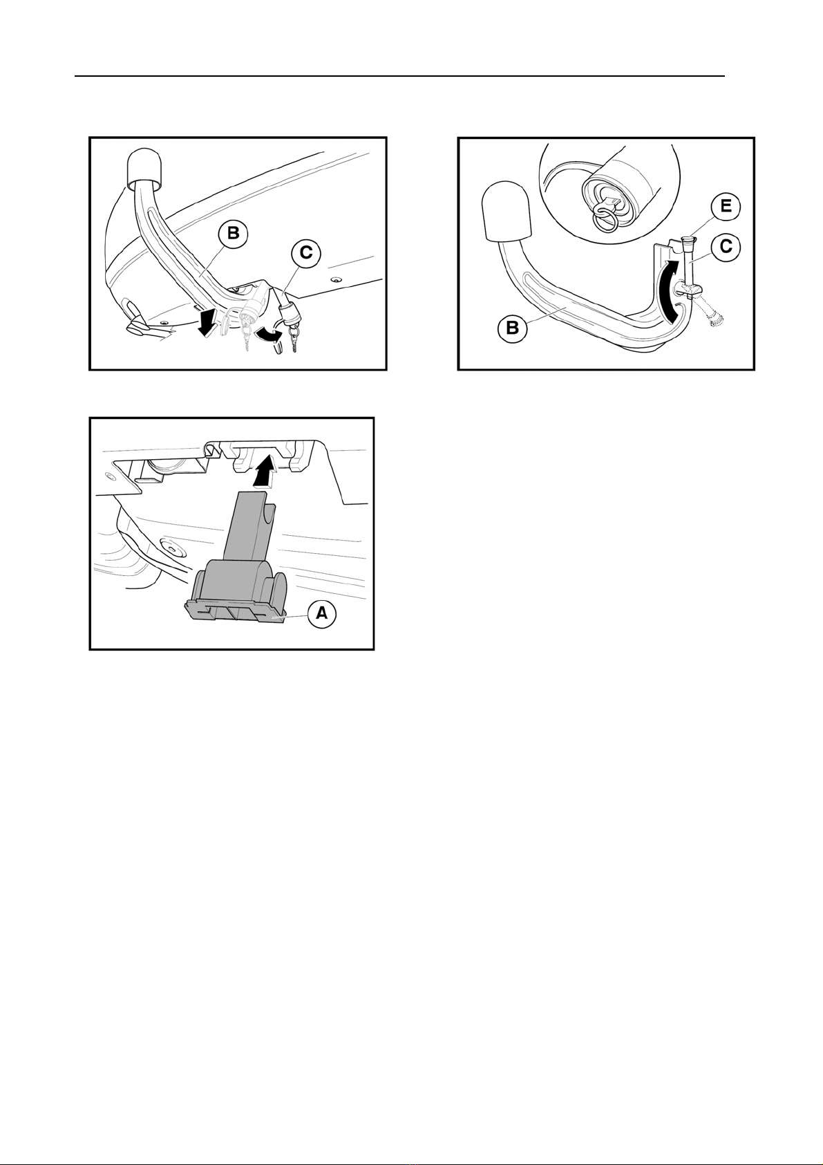
- 1 -
- Remove the protective plug (A) from the opening of the clamping bush on the girder of
the towing coupling -arrow- and put it in a convenient place.
Prior to inserting the towing arm, always make sure that the clamping bush is not
dirty.
Any dirt in the clamping bush must be unconditionally removed prior to use, because
it prevents the safe fastening of the towing arm!
(That is why is always necessary to replace the protective plug into the clamping bush after
removing the towing arm.)
- 2 -
- Grip the towing arm (B) and bring the control lever (C) from the storage position
-arrow- to the defined mounting position (i.e. when looking upon the towing arm from the
side of the control lever, the said lever must be directed downwards to the right from the
body of the towing arm, and the surfaces of the revolving eccentric are parallel with the
axis of the body.)
- 3 -
- Open the lid of the lock (E) of the control lever (C), and unlock the lock of the control
lever by turning the key 90° clockwise -arrow- (once the lock is unlocked, the key is in a
vertical position -detail-).
In this position, the key cannot be removed from the lock!
- 4, 5 -
- Grip the towing arm (B) with left hand, and fit it into the clamping bush shifting it
upwards vertically -arrow- so that the ends of the eccentric may fit into the recess in the
clamping bush up to the stop.
- In this position, with right hand turn the control lever (C) upwards -arrow- up to the stop.
Hold the lever by the handle (D), so that your fingers may not get caught between the lever
and the body of the towing arm, nor the inserted key may get bent.
- Turn the key 90° anticlockwise -arrow- and secure the lock of the control lever (once the
lock is locked, the key is in a horizontal position -detail-).
- Pull out the key and close the lid of the lock.
- Remove cover (F) from the ball journal -arrow-.
Finally, check whether the towing arm was mounted properly. Try its fitting by hand,
shaking it strongly. Tilt the socket of the electric installation downwards.
Important
- The towing arm cannot be fitted into the clamping bush without unlocking the control
lever.
- The towing arm is not mounted properly if it is not possible to lock the control lever and
to pull out the key. The control lever needs further tightening, pulling it upwards
moderately!

19
- Before driving, check whether the towing arm is secured to the clamping bush of the
girder of the towing coupling properly. The check is effected by turning the locked control
lever of the towing arm "downwards" slightly. If the lever can be turned through a small
angle only (about 5°), the clamping is all right. After the check, pull the lever back up to the
stop.
- Never unlock the towing arm with the trailer attached.
- Should you lose your key, contact the nearest authorised service or the manufacturer
directly.
Dismounting the towing arm
For dismounting the towing arm, proceed in the opposite way, in compliance with the
following instructions.
- 6 -
- Fit cover (F) upon the ball journal -arrow-.
- Open the lid of the lock (E) of the control lever (C), and open the lock by turning the key
clockwise -arrow- (once the lock is opened, the key is in a vertical position -detail-).
- 7 -
- Grip the towing arm (B) with left hand. Applying slight pressure, turn the control lever
(C) with right hand downwards to the indicated fitting position -arrow-. In this position, the
towing arm is released, and will fall down to your left hand by itself.
- 8 -
- Lock the lock of the control lever (C) (once the lock is locked, the key is in the horizontal
position -detail-), také out the key and close the lock with lid (E).
- Remove dirt from the towing arm (B) and bring the control lever -arrow- to the storage
position (parallel with the axis of the arm body).
- Put the towing arm into the luggage compartment and secure it against a move.
Caution!
Never leave the towing arm lying freely in the luggage compartment. In case of
sudden braking, it could threaten the safety of the passengers and cause damage to the
luggage compartment.
- 9 -
- Take the protective plug (B) and fit it into the clamping bush in such a way that the
interrupted rib at the bottom of the cover may be directed towards the front section of the
vehicle, and the side surfaces of the cover may cover the lateral orifices of the clamping
bush. Tilt the socket of the electric installation back under the bumper.
Operation and maintenance
- The towing coupling requires a minimum maintenance only. The inside mechanism of the
revolving eccentric of the towing arm is filled with a special grease lasting for the whole
service life of the coupling. The towing arm can be washed with water, however, it must
not be dipped into it.

20
- Clean the hollow of the clamping bush from time to time, and apply a suitable preserving
oil, e.g. WD 40.
- Grease the ball journal from time to time with a suitable lubricating grease.
- Take care to seal the lock of the control lever with the lid carefully, to avoid dirt
collection.
- In case of a long-time operation with the towing arm mounted, in order to provide
for the proper functioning of the clamping mechanism, once in a month it is necessary
to disconnect the towing arm, to clean it and to apply a suitable preserving agent (e.g.
WD 40 or a similar preserving oil) and to turn the lock several times.
- If you are not using the towing coupling, dismount the towing arm and put it into the
car boot.
- When storing the towing arm in the luggage compartment, always fit the cover upon the
ball journal to avoid dirt collection.
Important Advice
- Check the function of all lights on the trailer after coupling the trailer and pluging
the trailer to the plugbox on the towing vehicle.
- Any alternations of the towing equipment are not allowed.
- The towing coupling must not be operated if the towing arm cannot be locked, or it is
possible to turn the control lever freely in the locked position.
- The towing coupling must not be operated if it is damaged or not complete.
- In case of the trailer not being coupled with the car, the ball pivot must be protected
by a plastic cover!
- The towarm should be stored properly in in boot to prevent damgage to the car or
any injury of the passangers at sudden braking. The ball pivot shoult be covered by
its plastic cover.
- The operation with the trailer presents higher demands upon the cooling system of
the towing vehicle. With the eventual requirements concerning the drive with the
trailer, contact the contractor.
- After running the first about 500 km with a trailer it is necessary to re-tighten the
bolts fixing the crossbeam to the car underbody and bolts fixing the towarm with the
prescribed torques! We recoment to have this check done in your nearest authorized
service station.
When using the towing coupling, follow the instructions given in this Assembly
Manual. The manufacturer is not responsible for any damages resulting from an
improper mounting of the towing arm, its overloading or damage due to a car
accident.
PROF SVAR s. r. o., the manufacturer wishes you a safe journey.
The information on the technical data, design, equipment, materials, guarantees and outside appearance
refer to the period when the mounting instructions are sent to print. The manufacturer reserves the right to
changes (including the change in technical parameters with reference to the individual model measures).
Table of contents
Other PS Automobile Accessories manuals


