PS TMB PS 079 User manual

1
KIA Cee‘d
KIA Cee’d SW (Sporty Wagon)
2006 →
Návod k obsluze a montáži
Betriebs und Montageanleitung
Owner’s and fitting Manual
TMB PS 079
Tažné zařízení
s přišroubovaným ramenem
Towing equipment
with bolt-on tow arm
Anhängerkupplung
mit angeschraubten Kugelhals
E8 55R-01 55631
© 6.10.2011
2
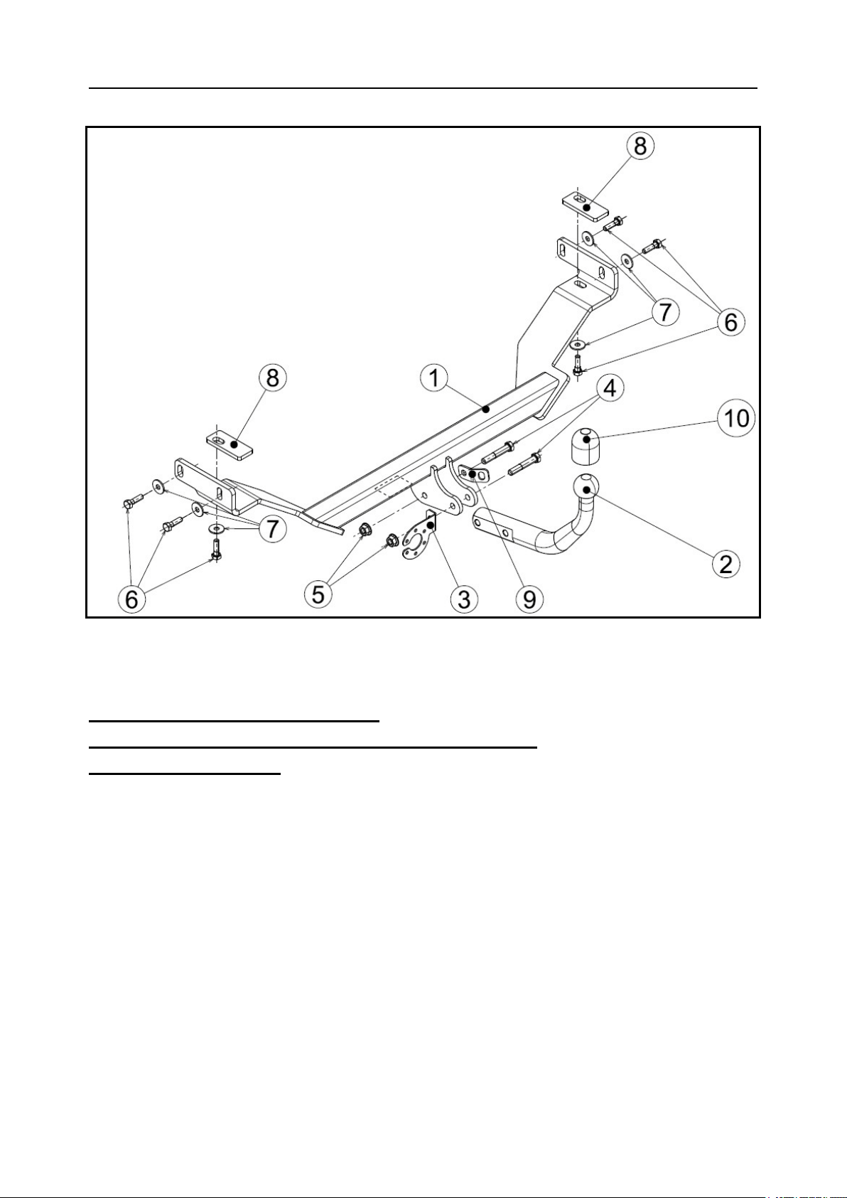
Seznam dílů tažného zařízení:
Verzeichnis der Teile der Anhängerkupplung:
List of components:
Název dílu Kusů Pozice
Bezeichnung des Teils, Name of the part Stück, Quantity Position, Positon
Nosník úplný (s identifikačním štítkem)
Träger vollständig (mit Identifikationsschild)
Beam assembly (with ID plate) 1 1
Tažné rameno (Kugelhals, Towarm) 1 2
Držák zásuvky (Steckdosenhalter, Plug box holder) 1 3
Šroub (Schraube, Bolt) M12 x 65 2 4
Matice (Mutter, Nut) M12 2 5
Šroub (Schraube, Bolt) M10 x 1,25 x 35 6 6
Podložka (Unterlegscheibe, Washer) 10,5 6 7
Vymezovací podložka (Distanzscheibe, Spacer washer) 2 8
Pojistné oko (Sicherungsöse, Safety lug) 1 9
Krytka kul. čepu (Kugelbolzendeckel, Cover of the ball) 1 10
Samolepící štítek (Selbstklebeetikette,
Self-adhesive sticker) „75 kg“ 1 -
1
3
KIA Cee´d
3
4
2

4
KIA Cee´d Sporty Wagon
6
5
7

5
TAŽNÉ ZAŘÍZENÍ - KIA Cee‘d, KIA Cee’d Sporty
Wagon (SW)
typ TMB PS 079
Tažné zařízení, t ypové oz načení TMB PS 079, je určeno pro připojení přívěsů o celkové
hmotnosti do 1 500 kg za osobní automobily KIA Cee‘d a KIA Cee‘d SW.
Všeobecné údaje
Konstrukce zařízení odpovídá všem českým i mezinárodním předpisům. Tažné rameno je
opatřeno kulovým čepem o průměru 50 mm dle normy ISO 3853.. Zařízení prošlo pevnostními
zkouškami dle evropského předpisu EHK č.55.
Parametry
Maximální celková hmotnost brzděného přívěsu 1 500 kg
Maximální celková hmotnost nebrzděného přívěsu 605 kg
Platí omezení hmotnosti přívěsu dle technického průkazu vozidla!
Maximální svislé statické zatížení na kouli 75 kg
Průměr kulového čepu 50 mm
Vztažná síla DC
CT
CT
gD
C
+
⋅
⋅=
8,9 kN
g – tíhové zrychlení (g = 9,81 ms-2)
T – hmotnost tažného vozidla [t]
C – hmotnost přívěsu [t]
Celková hmotnost tažného zařízení 17 kg
Rozměry 1103 x 498 x 299 mm
Seznam speciálního nářadí
Momentový klíč
Pila
Návod k montáži na vozidlo
Podle seznamu zkontrolujte jednotlivé součásti tažného zařízení.
1. Ustavte vozidlo na ramena dílenského zvedáku.
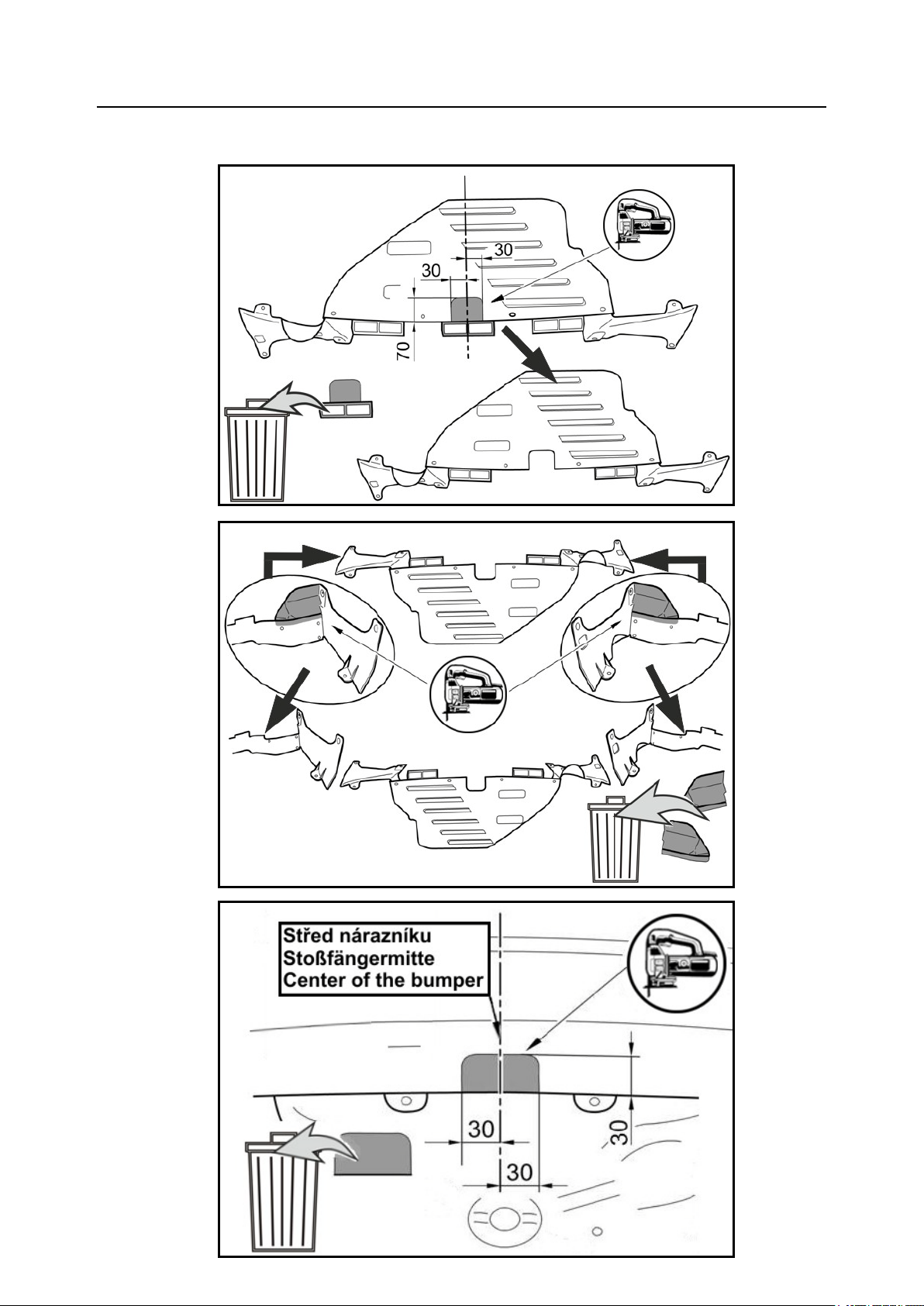
2. KIA Cee´d: Demontujte spodní plastový kryt a podle obrázků 2 a 3 vyřízněte části označené
šedou barvou.
KIA Cee´d SW: Demontujte spodní plastový kryt na levé straně vozu.
3. KIA Cee´d: Demontujte výfuk ze zadního pryžového uložení.
KIA Cee´d SW: Demontujte zadní nárazník.
4. KIA Cee´d: Dle obrázku 4 vyřízněte část zadního nárazníku.
6
KIA Cee´d SW: Ze zadního nárazníku demontujte spodní plastový díl (viz obrázek 5). Dle
obrázku 6 odřízněte z tohoto dílu čtyři části označené šedou barvou. Tyto části namontujte
zpět na nárazník (viz obr.7).
5. Z okolí upínacích otvorů na karoserii odstraňte případný plastizol a v těchto otvorech očistěte
jemný závit.
6. Volně namontujte nosník tažného zařízení pomocí šesti šroubů M10 x 1,25 x 35 (6), podložek
(7) a vymezovacích podložek (8) – viz obrázek 1. Tažné zařízení zatáhněte směrem dozadu
od vozidla a šrouby (střídavě) na obou stranách dotáhněte na utahovací moment 40 Nm.
7. Pokračujte montáží elektrické instalace tažného zařízení na voz idlo ( viz. ná vod k m ontáži
elektrické instalace pro tažné zařízení). Zásuvku e lektroinstalace přišroubujte až s montáží
tažného r amena. Po skončení montáže elektrické instalace namontujte zpět všechny
demontované díly a příslušné spoje utáhněte předepsanými utahovacími momenty.
8. Nasaďte tažné rameno (2) mezi držáky a upevněte pomocí šroubů M12x65 (4) a matic M12
(5). D le obr ázku 1 namontujte držák z ásuvky ( 3) a pojistné oko (9). T yto š roubové s poje
utáhněte momentovým klíčem na utahovací moment 80 Nm.
9. Na zadní nárazník nad tažné rameno nalepte samolepící štítek „75 kg“ (příslušné místo před
nalepením očistěte a odmastěte).
10. Na kulový čep tažného ramena nasaďte krytku (10).
Montáž tažného zařízení vyžaduje použití dílenské příručky, proto ji může provést pouze
autorizovaný servis.
Elektrická instalace pro tažné zařízení není součástí dodávky a je třeba ji objednat
samostatně.
Upozornění pro zákazníka
- Po ujetí prvních cca 500 km s přívěsem je nutné zkontrolovat dotažení upínacích šroubů
nosníku k podvozku vozidla, dotažení šroubů tažného ramena a případně je dotáhnout
předepsanými utahovacími momenty! Tuto kontrolu Vám doporučujeme provést v
nejbližším autorizovaném servisu.
- Kulový čep dle potřeby namažte vhodným mazacím tukem.
- Po připojení přívěsu a propojení el. instalace zkontrolujte funkci světel.
- Veškeré změny a úpravy tažného zařízení jsou nepřípustné.
- Při používání tažného zařízení dodržujte pokyny uvedené v tomto návodu.
- Výrobce na sebe nebere zodpovědnost za škody způsobené chybně namontovaným
tažným ramenem, jeho přetěžováním nebo jiným mechanickým poškozením.
- Tažné zařízení nesmí být provozováno je-li poškozeno nebo je neúplné.
- Není-li připojen přívěsný vozík k tažnému zařízení, musí být kulový čep chráněn
krytkou!
- Tažné rameno (pokud ho budete demontovat) uložte a zajistěte v zavazadlovém prostoru
tak, aby při náhlém zabrždění nemohlo ohrozit bezpečnost cestujících a způsobit
poškození zavazadlového prostoru. Na kulový čep tažného ramena nasaďte krytku.

7
Záruční list
Výrobce tažného zařízení poskytuje záruku na konstrukci, použitý materiál, výrobní provedení a
funkci dodaného tažného zařízení 24 měsíců od data prodeje.
Reklamaci v ýrobku v zákonné lhůtě uplatní kupující u prodávajícího. Oprávněnost reklamace
posoudí zástupce prodávajícího spolu se zástupcem výrobce v souladu s platnými předpisy.
Podmínkou platnosti záruky je, aby tažné zařízení bylo používáno pouze k účelům, ke kterým je
určeno.
Kupující je povinen prověřit stav zboží při jeho převzetí. V případě poškození zboží, nedodání
části tažného zařízení apod. je kupující povinen tuto skutečnost neprodleně ohlásit prodávajícímu
a to bez zbytečného odkladu po převzetí zboží.
Všechny součásti a příslušenství tažného zařízení musí být před odbornou montáží, zkontrolovány
ve vz tahu k jejich k ompaktibilitě na odpovídající typ vozidla. Tažná zařízení, smí být použita
pouze na v ýrobcem uve dený t yp voz idla. V případě neodborné montáže či montáže tažného
zařízení na typ vozidla, pro který není tažné zařízení určeno, neodpovídá výrobce za případné
poškození tažného zařízení, způsobené vadnou montáží či jeho nesprávným použitím.
Prodávající odpovídá za vady, které mělo tažné zařízení při jeho převzetí kupujícím.
Záruka se nevztahuje na škody mající původ v běžném opotřebení, v přetěžování a neodborném
používáním tažného zařízení, dále pokud není užíváno v souladu s pokyny uve dnými v návodu
k obsluze. Záruka se dále nevztahuje na škody způsobené živelnými vlivy. Prodávající rovněž
neodpovídá za škodu v případě, kdy bylo tažné zařízení změněno či jinak upraveno.
Záruka z aniká, b ylo-li tažné zařízení poškozeno havárií (kromě havárie vyvolané samotným
tažným zařízením) nebo zásahy do jeho mechanismu a konstrukce.
Typové osvědčení
Výrobce potvrzuje, že tažné zařízení bylo vyrobeno podle schválené dokumentace a odpoví dá
homologaci E8 55R-01 55631.

8
ANHÄNGERKUPPLUNG FÜR
KIA Cee‘d, KIA Cee’d Sporty Wagon (SW)
Typ TMB PS 079
Die Anhängerkupplung Typ TMB PS 079 ist für das Ankuppeln von Anhängern mit einer Masse
bis 1 500 kg an die Pkw KIA Cee‘d und KIA Cee‘d SW bestimmt.
Allgemeine Angaben
Die Konstruktion der Einrichtung entspricht der Verordnung des Ministeriums für V erkehr der
CR, s owie a uch a llen anderen r elevanten na tionalen und i nternationalen V orschriften. D er
Zugarm is t mit e inem Kugelbolzen von D urchmesser 50 m m l aut de m S tandard ISO 3853
versehen. D ie V orrichtung w urde au f F estigkeit l aut d er eu ropäischen R eglement E CE 55
geprüft.
Parameter
Max.Anhängermasse, gebremst 1 500 kg
Max.Anhängermasse, ungebremst 605 kg
Es gilt die Gewichtseinschränkung gemäß des Fahrzeugszulassungsscheines!
Stütztlast 75 kg
Durchmesser des Kugelbolzens 50 mm
DC-Wert 8,9 kN
CT
CT
gDC
+
⋅
⋅=
g – Fallbeschleunigung (g = 9,81 ms-2)
T – Gewicht des Zugfahrzeugs [t]
C – Anhängergewicht [t]
AHK Gesamtgewicht 17 kg
Maße 1103 x 498 x 299 mm
Verzeichnis Spezialwerkzeug
Drehmomentschlüssel
Säge
Anleitung zur Montage der Anhängerkupplung an das
Fahrzeug
Überprüfen Sie Die Befestigungsteile auf Vollständigkeit.
1. Fahrzeug mit dem Werkstattheber hochheben.
2. KIA Cee´d: Demontieren Sie die untere Kunststoffabdeckung und schneiden gemäß dem Bild
2 und 3 die mit grauen Farbe gekennzeichnete Teile aus.
KIA Cee´d SW: Demontieren Sie die untere Kunststoffabdeckung auf der linken Seite des
Fahrzeugs.
3. KIA Cee´d: Hängen Sie den Auspuff von der hinteren Gummihalterung ab.

9
KIA Cee´d SW: Demontieren Sie die hintere Stoßstange.
4. KIA Cee´d: Gemäß dem Bild 4 schneiden Sie ein Teil der hinteren Stoßstange aus.
KIA Ce e´d S W: Demontieren S ie di e unt ere K unststoffabdeckung von de r hi nteren
Stoßstange ab (siehe Bild 5). Gemäß dem Bild 6 schneiden Sie von diesem Teil die vier mit
grauer Farbe gekennzeichneten Teile aus. Montieren Sie diese Teile zurück an die Stoßstange
(siehe Bild 7).
5. Beseitigen Sie aus der Umgebung von Befestigungsöffnungen den ggf. vorhandenen Plastisol
und reinigen Sie das feine Gewinde in den Öffnungen.
6. Montieren S ie vor läufig de n T räger de r A nhängekupplung m it Hilfe von s echs S chrauben
M10 x 1,25 x 35 (6), Unterlegscheiben (7) und Distanzscheiben (8) - siehe Bild 1. Ziehen Sie
die Anhängekupplung nach Hinten vom Fahrzeug und ziehen sie die Schrauben abwechseln
auf beiden Seiten auf das Anzugsdrehmoment von 40 Nm.
7. Setzen Sie mit der Elektroinstallation bei d em Fahrzeug fort (siehe die Montageanleitung –
Elektrik f ür Z ugvorrichtung). Schrauben S ie d ie S teckdose erst n ach d em Einbau dem
Zugarm fest. Nach Beendung der Montage der Elektroinstallation sind alle demontierten Teile
wieder a nzubauen un d di e z uständigen V erbindungen m it de n vor geschriebenen
Drehmomenten anzuziehen.
8. Setzen S ie de n K ugelhals ( 2) z wischen di e H alter und be festigen S ie i hn m it H ilfe von
Schrauben M 12x65 ( 4) und M uttern M 12 ( 5). G emäß de m Bild 1 montieren S ie de n
Steckdosenhalter (3) un d die Sicherungsöse ( 9). Z iehen S ie di ese S chraubverbindungen m it
dem Momentschlüssel auf das Anzugsdrehmoment von 80 Nm.
9. Kleben Sie auf den Hinterstoßfänger über die AHK den Aufkleber „75 kg“
(die zuständige Stelle ist vor dem Aufkleben zu säubern und zu entfetten).
10. Setzen Sie eine Haube auf den Kugelbolzen auf (10).
Vor der Montage der Kupplung sollte man das Handbuch lesen, daher sollte die Montage
eine Vertragswerkstatt durchführen.
Die elektrische Installation ist nicht ein Bestandsteil der Lieferung und sie muss separat
bestellt werden.
Hinweis für den Kunden
-Nach d em Zurücklegen d er ers ten ca . 5 00 k m mit A nhänger i st d er D rehmoment d er
Spannschrauben d es T rägers zum Fahrgestell de s F ahrzeugs und d ie Sc hrauben de s
Kugelhalses zu überprüfen und gegebenenfalls mit dem vorgeschriebenen Drehmoment
nachzuziehen! Wir empfehlen diese Kontrolle im nächstgelegenen autorisierten Service
vornehmen zu lassen.
-Schmieren Sie den Kugelbolzen bei Bedarf mit einem geeigneten Schmierfett ein.
-Überprüfen Si e nach de m A nschluss de s A nhängers u nd der V erbindung de r
Elektroinstallation die Funktion der Scheinwerfer.
-Es sind keinerlei Änderungen und Modifikationen der Anhängerkupplung zulässig.
-Halten Sie di e i n dieser A nleitung a ngeführten A nweisungen bei der V erwendung der
Anhängerkupplung ein.
-Der H ersteller n immt k eine S chadensverantwortung a uf s ich, d ie d urch f ehlerhaft
angebauten Kugelhals, seine Überbelastung oder sonstige mechanische Beschädigungen
verursacht werden.
-Die A nhängerkupplung da rf n icht i n B etrieb g enommen w erden, falls s ie be schädigt
oder unvollständig ist.
-Falls de r A nhänger ni cht a n der A nhängerkupplung a ngeschlossen i st, i st de r
Kugelbolzen mit einer Kappe zu versehen!

10
-Lagern und sichern Sie den Kugelhals (falls Sie ihn abnehmen) im Gepäckraum so, dass
beim p lötzlichen B remsen d ie S icherheit d er R eisenden n icht g efährdet, u nd k eine
Beschädigungen des G epäckraums v erursacht w ird. S etzen S ie ei ne K appe a uf d en
Kugelbolzen des Kugelhalses auf.
Garantieinformationen und Bedingungen
Der Hersteller de r A nhängerkupplung gewährt a uf K onstruktion, ve rwendetes M aterial,
Produktionsausführung und F unktion de r ge lieferten A nhängerkupplung e ine G arantie von 24
Monaten ab Verkaufsdatum.
Die Reklamation des Produkts in der gesetzlichen Frist macht der Käufer beim Verkäufer geltend.
Die B erechtigung d er R eklamation b eurteilt ei n Vertreter d es V erkäufers z usammen m it ei nem
Vertreter des Herstellers entsprechend der gültigen Vorschriften.
Bedingung für die Gültigkeit der Garantie ist, dass die Anhängerkupplung zum für sie bestimmten
Zweck angewendet wurde.
Der K äufer i st ve rpflichtet, de n Zustand d er W are be i Ü bernahme z u übe rprüfen. B ei
Beschädigung der Ware, fehlendem Teil der Anhängerkupplung, u.ä. ist der Käufer verpflichtet,
diese T atsache unve rzüglich de m V erkäufer z u m elden, di es ohne u nnötigen V erzug na ch
Warenübernahme.
Alle T eile und da s Z ubehör de r A nhängerkupplung m uss vor de r f achgerechten M ontage i n
Beziehung z ur K ompatibilität f ür den e ntsprechenden F ahrzeugtyp kont rolliert w erden.
Anhängerkupplungen dürfen nur am vom Hersteller angeführten Fahrzeugtyp benutzt werden. Bei
nicht f achgerechter M ontage ode r M ontage de r A nhängerkupplung an einen F ahrzeugtyp, f ür
welchen s ie n icht b estimmt i st, h aftet d er Hersteller n icht f ür ev entuelle B eschädigungen d er
Anhängerkupplung, verursacht durch fehlerhafte Montage oder falsche Benutzung.
Der Verkäufer h aftet für M ängel, w elche d ie A nhängerkupplung b ei Ü bernahme d urch d en
Käufer hatte.
Die Ga rantie b ezieht sich n icht auf Schäden, d ie i hre U rsache i n n ormalem V erschleiß,
Überlastung und ni cht f achgerechter B enutzung der A nhängerkupplung haben, w eiter w enn s ie
nicht g emäß d er A nweisungen i n de r G ebrauchsanleitung be nutzt w urde. D ie G arantie b ezieht
sich w eiter n icht au f durch N aturkatastrophen v erursachte S chäden. D er Verkäufer h aftet
ebenfalls nicht für Schaden, wenn die Anhängerkupplung geändert oder angepasst wurde.
Die Garantie erlischt, wenn die Anhängerkupplung durch einen Unfall beschädigt wurde (außer
einem Unfall, hervorgerufen durch die Anhängerkupplung) oder bei Eingriff in ihren
Mechanismus und Konstruktion.B
Typengenehmigung
Der Hersteller bestätigt, dass die Anhängerkupplung laut der genehmigten Dokumentation
hergestellt wurd und folgender Typenzulassung entspricht E8 55R-01 55631.

11
TOWING DEVICE - KIA Cee’d, KIA Cee’d Sporty
Wagon (SW)
Type TMB PS 079
The towing d evice, t ype designation TMB PS 079, i s designed for coupling of trailers with the
total weight up to 1 500 kg behind the passenger cars KIA Cee‘d and KIA Cee’d SW.
General data
The s tructure of t he de vice c orresponds t o t he Decree of t he M inistry of T ransportation of t he
Czech R epublic and to all C zech and international regulations. The towing arm has a b all stud
with th e d iameter o f 5 0 mm a ccording to th e ISO 3853 standard. T he device p assed t he t ests
according to the European Regulation No.55 Revision 1.
Parameters
Maximum total weight of the braked trailer 1 500 kg
Maximum total weight of the not braked trailer 605 kg
Limited by registration book of the car!
Maximum vertical static load on the ball 75 kg
Diameter of the ball stud 50 mm
Theoretical relative force DC-value 8,9 kN
CT
CT
gDC
+
⋅
⋅=
g – gravitational acceleration (g = 9,81 ms-2)
T – towing car weight [t]
C – trailer’s weight [t]
Total weight of the towing equipment 17 kg
Dimensions 1103 x 498 x 299 mm
List of special tools and gadgets
Torque spanner
Saw
Instructions for mounting to the vehicle
Check contents of the towbar package against the part list.
1. Position the car over the workshop lift.
2. KIA Cee´d: Dismount the bottom plastic cover and according to figures 2 and 3 cut out the
parts marked by gray color.
KIA Cee´d SW: Dismount the bottom plastic cover on the left side of vehicle.
3. KIA Cee´d: Dismount the exhaust pipe from the rear rubber placement.
KIA Cee´d SW: Dismount the rear bumper.
4. KIA Cee´d: According to figure 4 cut out a part of the rear bumper.

12
KIA Ce e´d S W: Dismount t he bottom p lastic p art from t he re ar b umper (s ee fi gure 5 ).
According to figure 6 c ut off from this part four portions marked by gray color. Mount back
these portions on the rear bumper (see figure 7).
5. Remove (if necessary) the plastic protection from close of the fixing holes and clean the fine
thread in these holes.
6. Loosely fix the beam assembly with six bolts M10 x 1,25 x 35 ( 6), washers (7) a nd spacer
washers (8) – see figure 1. Draw the structure backwards from the car and tighten the bolts in
turns on both sides by the torque 40 Nm.
7. Go o n w ith e lectrical i nstallation o f to wing d evice o n th e c ar ( see a ssembly in structions
enclosed to w iring k it). Screw t he s ocket hol der w ith m ounting of t he t ow a rm. After
completing th e electric installation, mount b ack all dismantled parts and tighten a ll relative
joints by prescribed torques
8. Fix the towing arm (2) between the holders by means of two bolts M12x65 (4) and nuts M12
(5). Mount the socket holder (3) and safety lug (9) according to figure 1 and tighten the bolts
by the torque 80 Nm.
9. On the rear bumper over the tow bar there is the place where you put the self-adhesive sticker
“75 kg” – (before sticking you must clean and degrease that place).
10. Cover the ball pivot by its protective lid (10).
For assembling of the towing device the workshop handbook is needed, therefore it can be
done only by accredited service.
Electrical installation is not delivery component and it must be ordered separately.
Advise for the user
- After d riving the f irst approx. 5 00 k m w ith a t railer i t i s n ecessary to ch eck t he b olts
fixing t he c rossbeam t o t he unde rbody a nd t he bo lts f ixing t he t ow ba r by a t ongue
wrench at prescribed torques! W e recommend to have this check done at your nearest
authorized service station.
- Grease the ball pivot as need be by a suitable lubricant.
- Check the function of all the lights on the trailer after coupling and plugging in.
- Any adjustments and modifications of the towing equipment are not allowed.
- Follow all instructions for the use published in this leaflet.
- The producer is not accountable for any damage resulting from incorrect installation of
the equipment, overloading or any other mechanical impairment.
- It is not allowed to use the equipment when it is damaged or incomplete.
- The pivot ball must be protected by its cover when nou trailer is coupled !
- The tow bar (in case it is dismounted) should be placed in the boot of the car in the way
not to endanger the passengers or damage the interior of the boot. The ball pivot must
have its cap on.

13
Guarantee information and conditions
The manufacturer of the towing coupling gives the guarantee for the construction, used material,
manufacturing execution and function of the supplied towing coupling for 24 months from the
date of sale.
The complaints are to be presented by the buyer to the selling organization within the legal period.
The rightfulness of the complaint will be judged b y a representative of the s elling organization
together with a representative of the manufacturer in accordance with valid regulations.
The prerequisite of validity of the guarantee is that the towing coupling has to be used only for
those purposes for which it is designed.
The buyer shall examine the condition of the goods at their reception. In case of any damage of
the goods or failure t o d eliver any p art of t he t owing coupling the bu yer s hall report s uch fact
immediately to th e s elling o rganization w ithout u nnecessary d elay a fter th e r eception of t he
goods.
All parts and accessories of the towing coupling must be checked before professional fitting with
regard to their compatibility w ith the r espective type o f vehicle. The towing couplings ma y b e
used only for the vehicle type stated by the manufacturer. In case of incompetent fitting or fitting
of t he towing coupling on a t ype of vehicle for which the towing coupling is not intended, the
manufacturer shall not be responsible for any damage of the towing coupling caused by defective
fitting or its incorrect use.
The selling organization is responsible for defects the towing coupling had at its reception by the
buyer.
The guarantee does not cover any damages resulting from common wear and tear, overloading
and unprofessional use, as well as damages caused by non-compliance with the instructions stated
in the operating manual. The guarantee does not cover any damages due to natural disasters. The
selling organization is not responsible for any damage in the case when the towing coupling was
modified or otherwise altered.
The guarantee also becomes void if the towing coupling has been damaged due to an
accident (except a ccidents c aused b y th e to wing coupling its elf) o r by ta mpering w ith its
mechanism and construction.
Compliance declaration
The producer of the towing equipment certifies hereby that it is produced according to the
approved documentation and complies with homologation E8 55R-01 55631.

14

15

16
Výstupní kontrola výrobce
Ausganginspektion des Herstellers
Manufacturer’s final inspection
Výrobce: Manufacturer: Hersteller:
PROF SVAR s.r.o., Přestavlcká 1474, CZ - 295 01 Mnichovo Hradiště,
Tel.: +420 326 771 704 Fax.: +420 326 771 230 E-mail: profsvar@profsvar.cz
Výrobní číslo
Produktionsnummer
Manufacturing number
Datum výroby
Herstellungsdatum
Date of manufacture
……………………………………………
Razítko a podpis prodávajícího
Stempel und Unterschrift des Händlers
Stamp and signature of seller
Datum prodeje
Datum des Verkaufes
Date of sales
LDPE
4
……………………………
……………………………
…………………………………………
……………………………
Table of contents
Languages:
Other PS Automobile Accessories manuals


