manuals.online logo
Brands
  1. Home
  2. •
  3. Brands
  4. •
  5. Red Smoke Alarms
  6. •
  7. Smoke Alarm
  8. •
  9. Red Smoke Alarms RFMDUAL User manual

Red Smoke Alarms RFMDUAL User manual

40mm
10mm Follow National/State Electrical Codes and any local state
legislation requirements. Cable sizing must be in
accordance with AS/NZS 3000:2018 wiring regulations and
adhere to state regulations a minimum of 1.0mm2 250 V.
Interconnect cable on alarms must be SDI cable. (No 4core/
aircon wire to be used) Failure to follow will void warranty.
Model: RFMDUAL
Flush Mount Dual 240V Mains Powered or
10 Year Lithium Battery Photoelectric Smoke
Alarm (RF Module Optional)
DIAGRAM
AVOID THESE LOCATIONS
IMPORTANT: If you are installing this product for use by others, you must leave this
manual (or a copy of it) for the end user.
Add the RF module (RFMOD) to this smoke alarm to enable wireless connection with
other RF wireless alarms/products from Red Smoke Alarms.
RFMDUAL is a photoelectric flush mount smoke alarm that provides versatile
functionality. It can serve as a 240V mains powered alarm with a 10-year lithium battery
backup. It can also be interconnected with other 240V Red smoke/heat alarms or
function as a standalone 10-year lithium battery smoke alarm with the option for wireless
interconnection using an RF module. The alarm is designed for convenient installation
with a 90mm cut out hole.
The flush mount design of the smoke alarm ensures that it remains level with the ceiling,
providing both effective protection and a discreet appearance.
This smoke alarm offers two power options: It can be powered either by a sealed-in 3V
non-replaceable lithium battery or by connecting it to AC mains power. If the smoke
alarm is connected to AC mains power, the lithium battery acts as a backup power
source that automatically activates in the event of an AC power failure. The lithium
battery is specifically designed to provide power for up to 10 years, ensuring continuous
functionality during extended power outages.
Under normal operating conditions, the 3V non-replaceable battery has an estimated
lifespan of 10 years, eliminating the need for frequent battery replacements. However, it
is still recommended to regularly test the smoke alarm to ensure proper functioning.
Avoid installing the smoke alarm in the following locations:
• Within one metre of heating or cooling supply vents, return air or fresh air vents, as
smoke may be blown away by the supply vents or diverted into the return air vent,
leading to improper alarms.
• In areas where the temperature may fall below 0°C or rise above 45°C, as smoke
alarms are designed to operate safely only within these temperature ranges. Operating
outside these limits may result in failure to alarm, improper alarms, or nuisance alarms.
• In damp or very humid areas, such as bathrooms with showers, where humidity levels
may rise above 95%. Above this level, moisture may condense inside the smoke
chamber, causing false alarms. Additionally, the smoke alarm may become unstable
below 5% relative humidity.
• In areas where particles of combustion are present, such as garages or kitchens, as
this can cause false alarms.
• In dusty or dirty areas where an installation cannot be relied on. An accumulation of
dust and dirt in the sensing chamber may block the openings and prevent an alarm or
cause false alarms. If a smoke alarm is required in such an area, vacuum it frequently
and test it according to the "Operation and Testing" section.
• In the dead air space in the corner where the wall meets the ceiling. If unsure about the
exact location of mounting, contact the local fire department for assistance in choosing
a safe location.
• In areas where bugs or insects are present, address the issue before installing the
smoke alarm. Although all smoke alarms built since 1985 are designed to prevent bugs
from entering the detection chamber, bugs may still build up on chamber openings and
prevent smoke from entering. If bugs are present, vacuum the unit frequently as
described in the maintenance section.
• Within one metre of a fluorescent or compact fluorescent lamp, as electrical "noise"
may cause nuisance alarms.
Power Source: 220-240V, 50Hz
10 Year 3V Lithium Battery (As mains power source or as
backup battery)
Operating Current: ≤48 mA
Sensing Type: Type A Photoelectric smoke alarm - contains NO radioactive
material
Temperature Range: 0°C to 45°C
Humidity Range: 5% to 95% (non-condensing)
Interconnecting: 40 alarms wires over 150 metres maximum
Sound Level: > 85dB at 3 metres minimum
Alarm Condition: Audible signal pattern (ISO 8201)
Visual Indicators: Green LED for mains power ON
Red LED for pairing, warning and low battery indication
Cut-out Hole Size: Ø90mm
Protrusion from ceiling: 31mm
Approval: AS 3786:2014
Maximum Lifespan: 10 years
IMPORTANT: READ ALL INSTRUCTIONS BEFORE INSTALLATION. NO USER
SERVICEABLE PARTS INSIDE THIS SMOKE ALARM.
Do not attempt to repair the smoke alarm yourself.
CEILING / WALL
JUNCTION
HEAT &
SMOKE
FROM
FIRE
300mm min
CEILING
NEVER HERE
BEST
HERE NEVER
HERE
DEAD AIR
SPACE
SIDE WALL
300mm min
APEX OF
SLOPING
CEILING
n
HEAT & SMOKE
FROM FIRE
DEAD
AIR SPACE
1500mm max
500mm mi
500mm min
BEST
HERE
BEST
HERE
SINGLE FLOOR
BEDROOMBEDROOM
BEDROOM W/C
KITCHEN DINING
BATH
TYPICAL
MULTIPLE FLOOR
INSTALLATION
BD/RM HALL BD/RM
KITCHEN
RUM PUS
LOUNGE
ROOM
LOUNGE ROOM
Recommended locations Fig.4
• Install at least one alarm for each bedroom
• Install at least one alarm to protect any stairway
• Install at least one alarm on every floor level.
• Install an alarm in every room where a smoker sleeps as additional protection.
• Install an alarm in every room where electrical appliances are operated (i.e. portable
heaters or humidifiers) as additional protection.
• Install an alarm in every room where someone sleeps with the door closed as
additional protection. The closed door may prevent the alarm from waking the sleeper.
• When mounting an alarm on the ceiling install it at a minimum of 300mm from the side
wall and 500mm max. from any corner (see diagram).
• When mounting an alarm on a wall, install it at a minimum of 300mm from the ceiling
level but not more than 500mm from the ceiling level and any corner (see diagram)
• When mounting an alarm at the apex of a sloping ceiling it should be located a
minimum of 500mm from the apex but should not exceed 1500mm (see diagram).
RECOMMENDED LOCATION OF ALARMS
INSTALLER PLEASE NOTE:
• WARNING: Please ensure to disconnect the mains power from the circuit.
• Prior to connecting the mains power, ensure wiring polarity is correct.
• This smoke alarm is designed for flush mounting only.
• This smoke alarm can be interconnected with other Red alarm devices including
R240, R240RC, RHA240SL. Connecting this smoke alarm to other brands or models
may result in potential damage or create risks such as electric shock or fire hazards.
• Up to 40 smoke alarms can be interconnected.
• The supply terminal block of the alarm consists of four labeled terminals: Interconnect,
N, E/LOOP, and A. It is essential to ensure proper wiring to ensure the alarm functions
correctly. Incorrect wiring can lead to damage to the unit and will void the warranty.
For guidance on the appropriate wiring, please refer to the provided wiring diagrams.
• The maximum length of wire used in interconnecting smoke alarms should not exceed
150 metres, and the spacing between interconnected smoke alarms must not exceed
30 meters per alarm. The minimum wire cross-section is 1.00mm2. Interconnected
smoke alarms must be connected to the same final sub-circuit.
• Do not use any wire that may be confused with normal house wiring for the
interconnect wire, such as green/yellow earth wire.
• Do not connect AC power wires to the Interconnect terminal, as this may damage
smoke alarms.
• Do not connect the Interconnect wire to any device other than the Interconnect
terminal of another Red alarm devices including R240, R240RC. Otherwise, the
RFMDUAL will be damaged.
• Smoke alarms should be interconnected only within the confines of a single-family
living unit. Interconnecting smoke alarms between different units may result in
excessive nuisance alarms. Residents may not be aware that smoke alarms are being
tested or that the alarm is a nuisance caused by cooking, etc.
CAUTION - EQUIPMENT INSTALLATION HAZARD
• Red LED flashes very quickly (3 times per second) without sound. This means neutral
connection is missing or wiring is incorrect.
• Please check wiring and connection of smoke alarms with flashing red LED and rectify
wiring issue immediately.
• An optional RF Module (RFMOD) can be purchased separately if wired connection is
not possible.
• Alternative Energy Sources - (Wind, Solar, UPS etc.) This product is designed to be
connected to a Pure or True Sine Wave 230V AC supply.
• It should not be connected to a power source that utilises an inverter, e.g. PV solar
panel, the Total Harmonic Distortion (THD).
• Light Dimmer Circuits – The alarm must not be powered from a light dimmer circuit
User Manual
Use an insulated screwdriver to
press the lock on the Flush
Mount Base. See Fig.5.
2 To install the hardwire and connect
the terminals on the Flush Mount
Base, break the side knockout.
See Fig.5.
1 Remove the Terminal Cover
Ring (Optional)
Terminal Cover
Flush Mount
Base
RF Module
Alarm unit
1
2
3
4
Fig.3
Alarm Unit: Ø110mm Alarm Unit: 65.7mm
Alarm Ring: Ø130mm
Green
LED
Red
LED
Fig.1 Fig.2
Interconnect
N
E/LOOP
A
Interconnect
N
E/LOOP
A
Interconnect
N
E/LOOP
A
Interconnect
N
E/LOOP
A
Interconnect
Netural
Earth
Active (Live)
Fig.6
Active / Line
Earth or Loop
Neutral
Interconnect
Prior to mounting the smoke alarm, it is important to carefully review the following
instructions. The smoke alarm comprises of two sub-assemblies: the Flush mount base
assembly and the alarm unit. Red recommends setting aside the alarm unit, which is
enclosed in a plastic dust cover, until the building commissioning phase. This phase
typically includes tasks such as sanding, painting preparation, painting, and flooring.
Please follow these steps to mount the smoke alarm:
1. Choose a suitable location on the ceiling for the smoke alarm.
2. Cut a Ø90mm hole in the ceiling.
3. Strip the Active, Neutral, and Interconnect (if used) wires as per the strip length
shown in Fig.6.
4. Remove the terminal cover to access the terminals.
5. Connect the wires to the appropriate terminals on the flush mount base, as
illustrated in Figure 6. Ensure that the screws are securely tightened.
Note: Never connect multiple RFMDUAL with RF Modules and hard wire
interconnection together.
Please note that the interconnect terminal of the RFMDUAL is solely intended for
hard wire connection directly to other smoke alarms and/or heat alarms.
6. Reattach the terminal cover.
7. Insert the flush mount base into the hole and tighten the two screws to clamp the
base onto the ceiling, as shown in Fig.8.
8. Please note that the alarm unit should not be removed from the plastic dust cover.
During commissioning, remove the dust cover and attach the alarm unit to the flush
mount base assembly. After removing the dust cover, please store it away from infants
and young children to prevent the risk of suffocation.
DUST COVER
The smoke alarm is packaged in a plastic dust cover for the following reasons:
1. To safeguard the alarm unit from dust during the building construction phase.
2. Red Smoke Alarms recommends keeping the alarm unit (in the dust cover) aside until
the building commissioning phase to prevent it from getting dusty.
WARNING: Clipping the Electronic Unit in the base will activate the battery. The
battery has been designed to have a lifespan of 10 years in normal working
condition.
Ceiling Clamp not
securely fastened
When the toggle position is engaged,
it signifies that the unit is not securely
fastened to the ceiling. In this state, it
is not possible to install the alarm unit.
Toggle position
indicates the alarm unit
is clamped onto ceiling.
Fig.8
STEPS TO ACTIVATE THE SMOKE ALARM:
1. Remove the alarm unit from the dust cover.
2. Insert the RF module into the alarm unit for wireless interconnection (optional).
SEE SECTION - RF WIRELESS INTERCONNECTION FOR FURTHER DETAILS.
3. Insert the alarm unit into the Flush Mount Base as shown in figure 7. Check the
direction of the Electrical Plate conductor on the alarm unit. Ensure the four electrical
plate could insert to the Electrical Plate Contact at the flush mount base.
4. Push the alarm unit firmly until it latches (clicks) onto flush mount base.
5. Turn on mains power and check the green and red LED function. The green LED
should glow to show main power present. The red LED will pulse every 48 seconds
(approximate) to indicate correct operation.
6. Hold the Test/Hush button for 1 seconds to check that the alarm works.
Fig.7
Back view of
Alarm Unit
Front view of
Alarm Unit
Flush Mount Base
Electrical Plate Conductor
Electrical Plate Contact
TEST/HUSH/
RF-PAIRING
BUTTON
Interconnecting Smoke Alarms
Model: RFMOD
(Sold Separately)
INTRODUCTION
SPECIFICATION
BATTERY
INSTALLATION - WIRED CONNECTION
MOUNTING INSTALLATION
ACTIVATE THE SMOKE ALARM
WIRING INSTRUCTIONS:
Press the lock on the Flush Mount Base
Terminal
Cover
Fig.5 KNOCKOUT
Break the side knockout.
RF WIRELESS INTERCONNECTION
PLANNING
MAINTENANCE, REPAIRS, AND SERVICE
Developing and implementing an escape plan is crucial for ensuring the safety of your
household in the event of a fire. To do so, it is recommended that you follow the steps
outlined below:
• Create a floor plan that identifies all doors and windows, as well as at least two escape
routes from each room. Note that for second-storey houses, rope or chain ladders may
be necessary.
• Hold a family meeting to discuss and review your escape plan, ensuring that each
member understands what to do in case of a fire.
• Designate a predetermined location outside of your home where all family members
can meet in the event of a fire.
• Ensure that everyone is familiar with the sound of the smoke alarm and conduct regular
practice drills of leaving the home when it goes off.
• Conduct fire drills at least every six months, including night-time drills.
• Practicing your escape plan allows you to test its effectiveness before an actual
emergency. It is crucial that every member of the household is aware of the plan, as
they may need to act quickly and independently in the event of an emergency.
IN CASE OF FIRE
• Leave the building immediately using your pre-determined plan of escape. Time is of
the essence, so do not waste time getting dressed or retrieving valuables.
• When exiting, do not open any internal doors without first feeling the surface. If the
door is hot or smoke is seeping through cracks, do not open it. Instead, use your
alternative exit. If the door is cool, place your shoulder against it, open it slightly, and
be prepared to shut it quickly if heat or smoke rush in.
• Stay close to the floor if the air is smoky and breathe shallowly through a wet cloth if
possible.
• Once outside, proceed to your designated meeting place and ensure that all family
members are present.
• Call the Fire Brigade from a neighbor's home, not from your own.
• Do not re-enter your home until officials confirm that it is safe to do so.
For additional information on fire safety, please contact your local Fire Brigade.
Developing and practicing a plan of escape is essential for ensuring the safety of your
household in the event of a fire. When the smoke alarm sounds, it is crucial that you
follow the steps outlined below:
If you observe any indication from the smoke alarm
and are uncertain about its condition, please refer to
the table below for the "LED Indicator" and "Siren" of
your smoke alarm. The table will help you determine
the current status of the alarm and the appropriate
action to be taken.
If you require further assistance, we recommend
reaching out to our technical support for inquiries.
You can find the contact details in this manual.
When it comes to maintaining, repairing, and servicing your smoke alarm, it is important
to follow proper guidelines. Please refer to the information below:
Maintenance:
To ensure optimal performance, it is recommended that the smoke alarm be inspected
monthly to check for dirt, dust, and insects. The alarm can be vacuumed or brushed with
a soft brush to remove accumulated dust, dirt, or kitchen grease. Additionally, applying a
small amount of surface spray to a cloth and wiping around and over the alarm which will
should deter insect ingress. After cleaning, always test the smoke alarm to ensure that it
is functioning correctly.
Repairs / Service:
In the event that the smoke alarm is defective, refrain from tampering with the unit. The
unit does not contain any user-serviceable parts. Seek professional assistance for
repairs or servicing.
LIMITATION OF SMOKE ALARMS
• When discussing the limitations of smoke alarms, it's important to keep the following
points in mind:
• Smoke alarms can only detect smoke if it reaches the device. This means that fires that
start in areas far away from the alarm, such as chimneys, walls, roofs, or another floor
of the building, may not be detected.
• If the smoke alarm is located outside of the bedrooms or on a different floor, it may not
be able to wake up individuals who are sound sleepers. For this reason, it is
recommended that a smoke alarm be installed in each bedroom to provide additional
protection.
• While smoke alarms can provide early warning of a fire and help save lives, they should
not be considered as an alternative to an insurance policy.
• Standard smoke alarms will not alert individuals who are hearing impaired. Special
purpose devices such as the Red Strobe Light and Vibrating Pad for Hearing Impaired
should be used in these cases to ensure that everyone in the building is alerted in the
event of a fire.
• By keeping these limitations in mind, individuals can take steps to maximize the
effectiveness of their smoke alarms and ensure that they are taking all necessary
precautions to protect themselves and their property from the dangers of fire.
•
This smoke alarm has a built-in Hush or Silence feature incorporated into the
Test/Hush button. If cooking or other non-hazardous sources cause the alarm to sound,
it can be temporarily Hush by depressing the Test/Hush button for 1 second.
The alarm
will then enter a dormant period for 10 minutes.
After the 10 minute dormant period, the smoke alarm will resume normal operation.
Note: After the Test/Hush button has been pressed, wait 10 minutes before any
additional testing is conducted to avoid any abnormal responses as the smoke alarm is
not sensitive to smoke during this period. See Fig.12 for details.
•
This smoke alarm has a self-diagnosis. If the smoke alarm detects the battery is low
and/or an internal fault, it will chirp. This alarm could be temporarily silenced by holding
the Test/Hush button for 1 second. The alarm will not chirp for 10 hours but the LED will
remain functioning. It is recommanded to replace the smoke alarm as soon as possible
after this period of time.
Note: Silence will not affect the basic fire warning functions of a smoke alarm. During
the silenced period, if the smoke alarm detects any smoke, it will still operate fire
warning (Rapid flashing red LED and chirping). See Fig.12 for details.
HUSH OR SILENCE FUNCTION
This smoke alarm has a built-in feature to detect the power source.
If the A (Active) connection is present and the alarm is activated, it operates as a
220-240V mains-powered smoke alarm. In this case, the battery acts as a backup and
lasts for 10 years from installation. See Fig. 7 for instructions on activating the
smoke alarm.
If the A (Active) connection is not present and the alarm is activated, it relies solely on
battery power. The battery, under normal conditions, lasts for 10 years from installation.
Instructions for activating the smoke alarm can be found in Fig.7.
OPERATION
TESTING
TESTING
• Before testing, please ensure that the smoke alarm has been activated, either through
its battery or AC power supply.
• Regularly testing the smoke alarm is crucial to ensure its proper functioning and early
detection of fires, regardless of whether it is powered by a battery or AC power.
1) To perform the test, press and hold the "HUSH/TEST" button for 1 second. This will
activate the alarm, indicating that the electronic circuitry and horn are functioning
correctly.
Note: If the alarm does not sound during the test, please check the battery or AC
power supply and ensure that the smoke alarm is connected to a continuous final
sub-circuit.
Note: At the same time, any alarm that is RF paired to the RF network or hardwire
interconnected to the smoke alarm will also be triggered within 30 seconds.
2) To deactivate the smoke alarm from the test mode, briefly press the test button once
again.
Note: Continuous chirping, erratic noise, or a low sound from the alarm may indicate a
defective alarm. In such cases, please return the unit to the place of purchase.
WARNING: Never use an open flame of any type to test your alarm. Check that all
interconnected smoke alarms operate during the test.
WARNING: Do not apply excessive force on the “HUSH/TEST” button this may
damage the smoke alarm and may void the warranty.
CAUTION: Smoke alarm should be tested on a monthly basis. To accurately test
the integrity of the sensing chamber use a smoke detector (aerosol) tester.
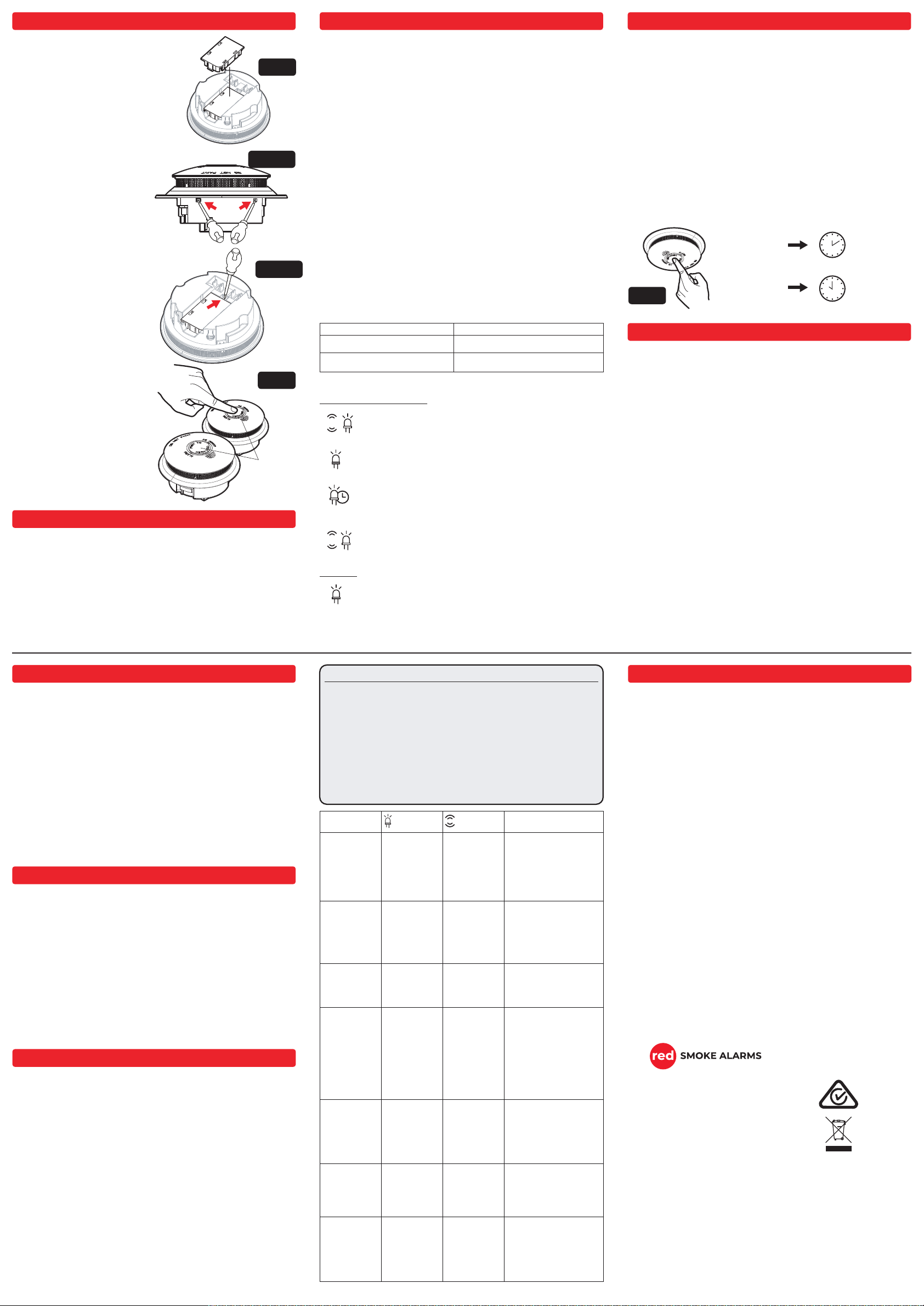
• Adjust the angle of the RF Module to be parallel
with the alarm unit and gently push the RF Module.
Please refrain from applying excessive force to
avoid damaging the RF Module. If the RF Module
does not fit into the alarm immediately, readjust the
angle of the RF Module and reinsert it.
• The alarm unit will have click sound to indicate the
RF module has been installed into the alarm unit.
INSTALL THE RF MODULE INTO THE ALARM
UNIT:
REMOVE THE MODULE CHIPS
FROM THE ALARM UNIT:
RF WIRELESS PAIRING INSTRUCTION
• To detach the alarm unit from the flush
mount base, utilise an insulated
screwdriver to press the button located
at the two arrow points. See fig.10.1
• Grasp the alarm unit firmly and utilise an
insulated screwdriver to push the head of
the RF Module, thereby removing the RF
module from the alarm unit. See fig.10.2.
PAIRING
• RFMDUAL as Master
– Press and hold the test button for 10
seconds until the alarms red LED turns
solid.
• RFMDUAL as Slave
– Press the test button 2 times quickly,
Alarm LED will flash for 5 times to
indicate successfully connection.
TESTING
• Follow steps in Section - “Testing” Press
and hold the test button 1 second, then
release.
• Smoke alarm will go off, paired smoke
alarms will also go off within 60 seconds.
Alarm red LED will flash for 60 seconds.
Clear Pairing Memory
– Press the test button 5 times, Alarm red
LED will flash for 10 times.
Fig.9
Fig. 10.2
Fig. 10.1
TEST/HUSH
& RF-PAIRING
BUTTON
Fig. 11
Memory Function
If one of the alarm indicators (RED LED) is flashing every 4
seconds, it indicates that a smoke alarm has previously been
activated.
Every
4 sec
Red
Standby
The red LED flashes once every 48 seconds to indicate the smoke
alarm and battery are functioning correctly.
Every
Red
40-60 sec
Low Battery
The smoke alarm signals low battery by flashing the red LED once
and emitting a chirp every 48 seconds.
Every
Red
40-60 sec
85dB
Fire Alarm
The smoke alarm will sound a loud alarm (85 dB) and the red LED
will flash rapidly. This will continue until the air is cleared.
85dB Red
Green LED
The green LED is illuminated when the mains power (220-240V) is
on. If the smoke alarm is powered only by battery. The Green LED
will not illuminated.
AC
Powered
Green
Featured LED and Alarm Signal
Green LED
Fig.12
HUSH
10 Minutes
SILENCE
10 Hours
False alarm
(Nuisance Alarm)
Low Battery
and/or
Fault Alarm
Red Smoke Alarms PTY. LTD. reserves the right to change specifications,modify designs
and discontinue items without incurring obligation and whilst every effort is made to ensure
that descriptions, specifications and other information in this catalogue are correct, no
warranty is given in respect of these of and the company shall not be liable for any error
therein.
© Red Smoke Alarms 2023
This material copyright under Australian and international laws. Except as permitted under
the relevant law, no part of this work may be reproduced by any process without prior
written permission of and acknowledgment to Red Smoke Alarm PTY. LTD..
WARRANTY
WARNING: DO NOT ATTEMPT TO OPEN THE HOUSING.
Red Smoke Alarms warrants the RFMDUAL to be free from defects in materials and
workmanships under normal use and service for a period of ten years from manufacture
date. The company will not be obligated to repair or replace parts which are found to be in
need of repair because of misuse, damage or alterations that occur after the date of
purchase. Return the RFMDUAL smoke alarm with proof of purchase to your local
distributor. The liability of the company arising from the sale of this RFMDUAL Smoke
Alarm shall not in any case exceed the cost of replacement and in no case shall the
company be liable for consequential loss or damages resulting from the failure of the
RFMDUAL Smoke Alarm.
RED SMOKE ALARMS PTY. SHALL HAVE NO LIABILITY FOR ANY PERSONAL
INJURY OR PROPERTY DAMAGE, OR ANY SPECIAL INCIDENTAL, CONTINGENT OR
CONSEQUENTIAL DAMAGE OF ANY KIND RESULTING FROM A FIRE. THE EXCLU-
SIVE REMEDY FOR BREACH OF THE LIMITED WARRANTY CONTAINED HEREIN IS
THE REPAIR OR REPLACEMENT OF THE DEFECTIVE PRODUCT AT RED SMOKE
ALARMS PTY. LTD. OPTION. IN NO CASE SHALL RED SMOKE ALARMS PTY. LTD.’S
LIABILITY UNDER ANY OTHER REMEDY PRESCRIBED BY LAW EXCEED THE
PURCHASE PRICE. YOUR RFMDUAL SMOKE ALARM IS NOT A SUBSTITUTE FOR
PROPERTY, DISABILITY, LIFE OR OTHER INSURANCE OF ANY KIND. APPROPRI-
ATE COVERAGE IS YOUR RESPONSIBILITY. CONSULT YOUR INSURANCE AGENT.
This does not affect your statutory rights.
This device is only suitable for single occupancy private dwellings only and not intended for
multi occupancy private dwellings or commercial or industrial dwellings.
Waste electrical products should not be disposed of with normal household waste. Please
recycle where facilities exist. Check with your Local Authority or retailer for recycling
advice. New regulation will encourage the recycling of Waste from Electrical and Electronic
Equipment (European "WEEE Directive" effective August 2005).
INDICATION AND ACTION
LED SIRENSTATUS ACTION NEEDED
INDICATOR
Green LED
illuminated
Red LED 1
flash every
48 seconds
None
Standby
Mode
(240v AC
mains
powered)
Red LED
flashing
rapidly until
smoke is clear
chirping
rapidly until
smoke is
clear
Fire Alarm
Mode
Smoke alarm in
standby condition,
powered by 240v AC
mains and backup
battery. No action
required.
Smoke Alarm detects
fire. See Section - “In
case of fire”
Red LED
flashing
rapidly for 3
seconds and
remain
illuminated for
60 seconds (if
without
deactivation)
chirping
rapidly for 3
seconds only
Fire Warning
Mode
Activate the test mode
by holding the test
button for 1 seconds.
Deactivate the test
mode by pressing the
test button 1 time.
See Section -
“TESTING”
Red LED 1
flashes every
48 seconds
1 short chirp
every 48
seconds
(Chirp pattern
sync with the
Red LED)
Low Battery
Warning The battery is low.
Check Section -
“Maintenance, Repairs,
and Service” for further
instruction.
Red LED 1
flashes every
4 seconds,
lasting 72
hours
None
Memory
Function
This indication will last
for 72 hours. Then, it will
automatically resume to
standby mode. No
action required.
Red LED 2
short flashes
every 48
seconds
2 short chirps
every 48
seconds
(Chirp pattern
sync with the
Red LED)
Unit Fault The alarm unit is faulty.
Check Section -
“Maintenance, Repairs,
and Service” for further
instruction.
Green LED
not illuminat-
ed
Red LED 1
flash every
48 seconds
None
Standby
Mode
(Powered by
Battery only)
Smoke alarm in
standby condition,
powered by internal
sealed battery power.
No action required.
Smoke Alarm Indication:
Red LED will flash rapidly for 3 seconds, then stay
solid
Red LED will turn off
Activation / Deactivation
Activate test mode: hold the test button for 1
second. (test mode will last for 60 seconds)
Deactivate the test mode: press the test
button for 1 time.
Contact Details
RED SMOKE ALARMS PTY. LTD.
35 Hitech Drive, Kunda Park QLD 4556
[email protected].
www.redsmokealarms.com.au
1300 316 552

Other Red Smoke Alarms Smoke Alarm manuals

Red Smoke Alarms R10RF User manual

Red Smoke Alarms

Red Smoke Alarms R10RF User manual

Red Smoke Alarms R10 User manual

Red Smoke Alarms

Red Smoke Alarms R10 User manual

Red Smoke Alarms RWB2 User manual

Red Smoke Alarms

Red Smoke Alarms RWB2 User manual

Red Smoke Alarms R9 User manual

Red Smoke Alarms

Red Smoke Alarms R9 User manual

Red Smoke Alarms R10RF User manual

Red Smoke Alarms

Red Smoke Alarms R10RF User manual

Red Smoke Alarms R240 User manual

Red Smoke Alarms

Red Smoke Alarms R240 User manual

Red Smoke Alarms RAC User manual

Red Smoke Alarms

Red Smoke Alarms RAC User manual

Red Smoke Alarms R240RC User manual

Red Smoke Alarms

Red Smoke Alarms R240RC User manual

Popular Smoke Alarm manuals by other brands

U-Line H-9471 manual

U-Line

U-Line H-9471 manual

Silent Alert UM3A-2212-EU-PSU quick start guide

Silent Alert

Silent Alert UM3A-2212-EU-PSU quick start guide

Firex FADC manual

Firex

Firex FADC manual

Honeywell Xtralis FAAST FLEX FLX-010 Product guide

Honeywell

Honeywell Xtralis FAAST FLEX FLX-010 Product guide

Universal SS-901-LR instructions

Universal

Universal SS-901-LR instructions

Sentrol ESL 518 Series installation instructions

Sentrol

Sentrol ESL 518 Series installation instructions

Visonic SMD-426 installation instructions

Visonic

Visonic SMD-426 installation instructions

Nexa EL1313/KD-101LC user manual

Nexa

Nexa EL1313/KD-101LC user manual

Kidde RF-SM-DC user manual

Kidde

Kidde RF-SM-DC user manual

ConMed ClearView 60-8585-120 Operator's manual

ConMed

ConMed ClearView 60-8585-120 Operator's manual

First Alert SA150B user manual

First Alert

First Alert SA150B user manual

Alecto SA20 manual

Alecto

Alecto SA20 manual

Masterbuilt MPS 230S manual

Masterbuilt

Masterbuilt MPS 230S manual

Marquant 006266 operating instructions

Marquant

Marquant 006266 operating instructions

SONA Electronics SM-SN-1 Installation and user guide

SONA Electronics

SONA Electronics SM-SN-1 Installation and user guide

First Alert PC910 user manual

First Alert

First Alert PC910 user manual

System Sensor DH400ACDCIHT Installation and maintenance instructions

System Sensor

System Sensor DH400ACDCIHT Installation and maintenance instructions

aguilera electronica AE002/OP Technical manual

aguilera electronica

aguilera electronica AE002/OP Technical manual

manuals.online logo
manuals.online logoBrands
  • About & Mission
  • Contact us
  • Privacy Policy
  • Terms and Conditions

Copyright 2025 Manuals.Online. All Rights Reserved.