FoxESS KH Series User manual

In order to prevent improper operation before use, please carefully read this manual.
KH/KA SERIES
User Manual


Table of Contents
1. Notes on This Manual ................................................................................................................. 1
1.1 Scope of Validity ....................................................................................................................1
1.2 Target Group ......................................................................................................................... 1
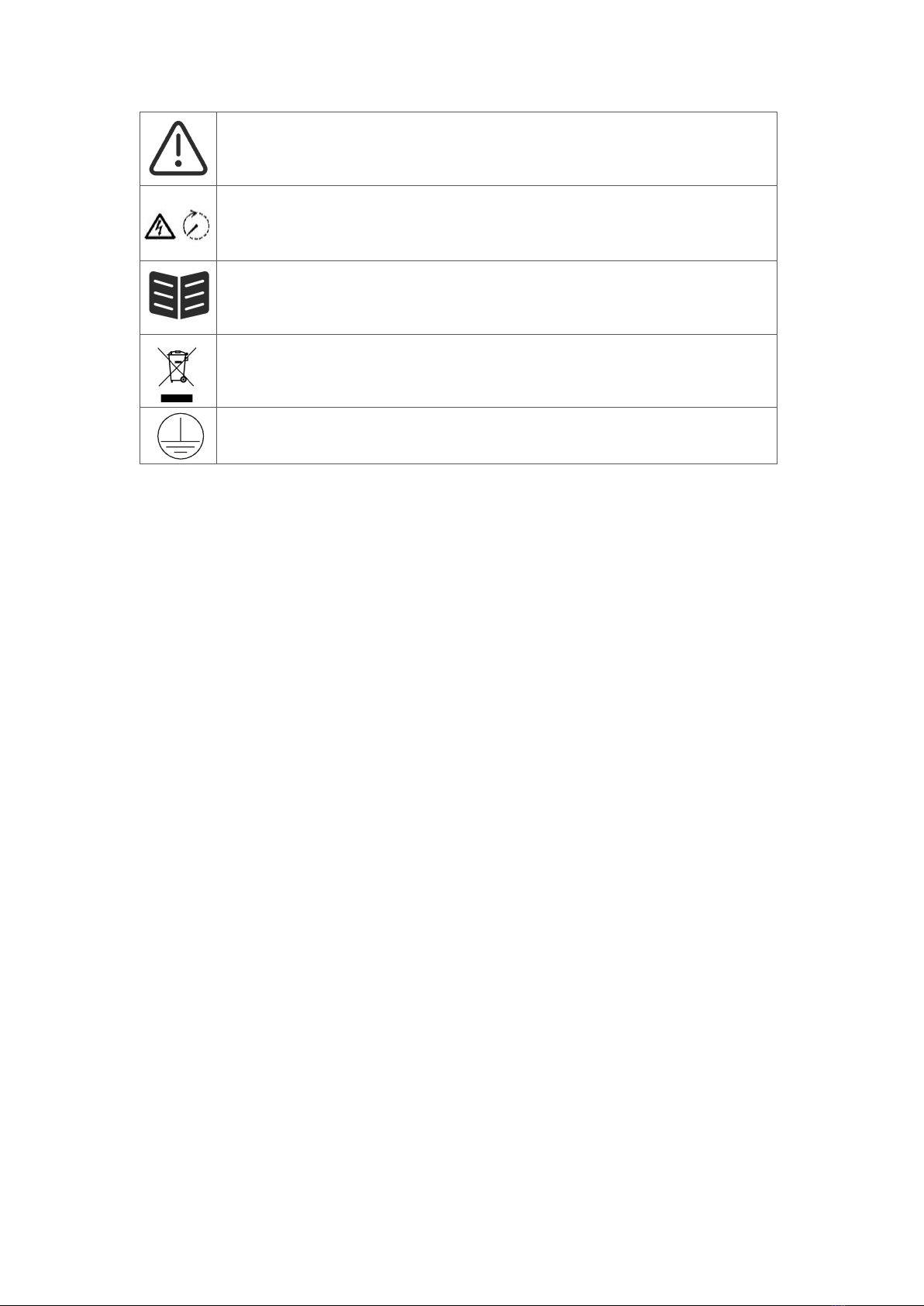
1.3 Symbols Used ........................................................................................................................1
2. Safety .............................................................................................................................................2
2.1 Appropriate Usage ................................................................................................................2
2.2 PE Connection and Leakage Current .................................................................................... 3
2.3 Surge Protection Devices (SPDs) for PV Installation .............................................................4
3. Introduction ................................................................................................................................... 4
3.1 Basic Features ....................................................................................................................... 4
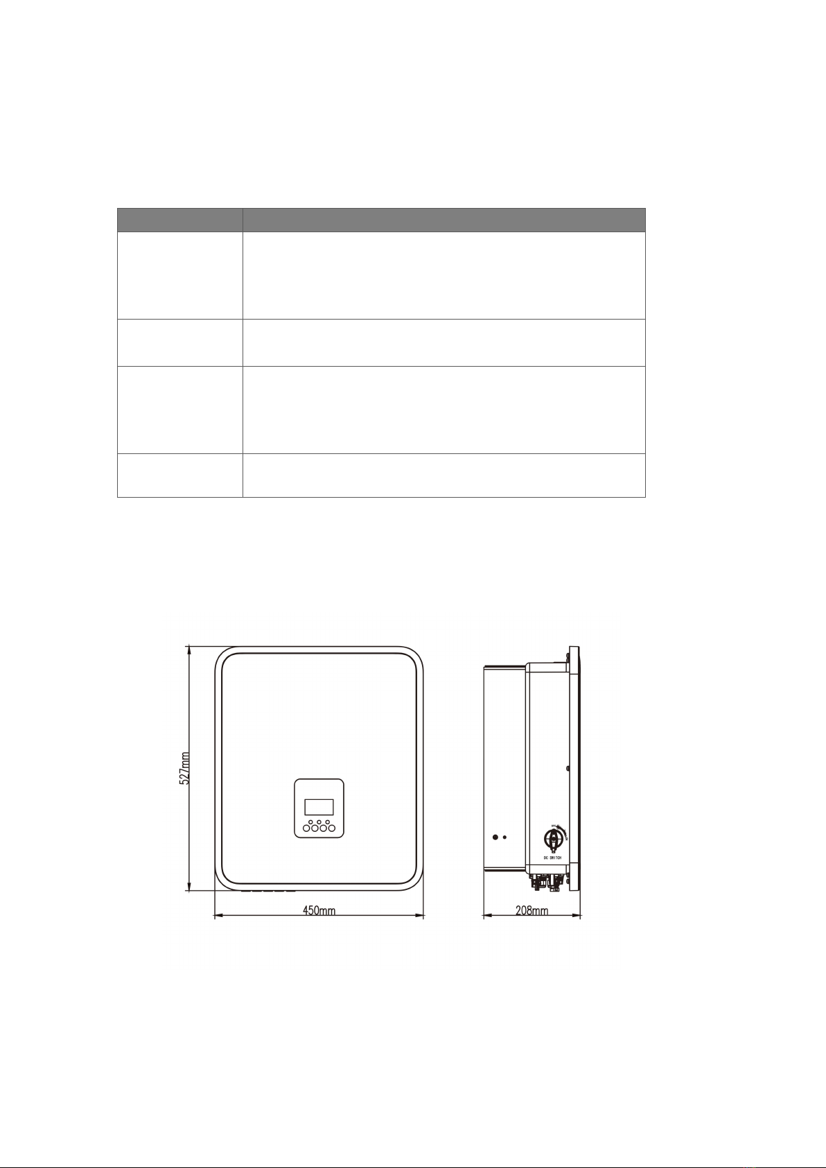
3.2 Dimensions ........................................................................................................................... 5
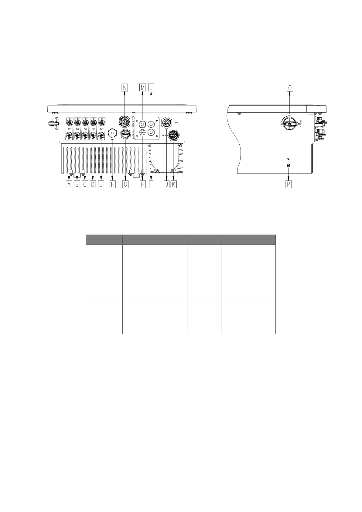
3.3 Terminals of inverter .............................................................................................................6
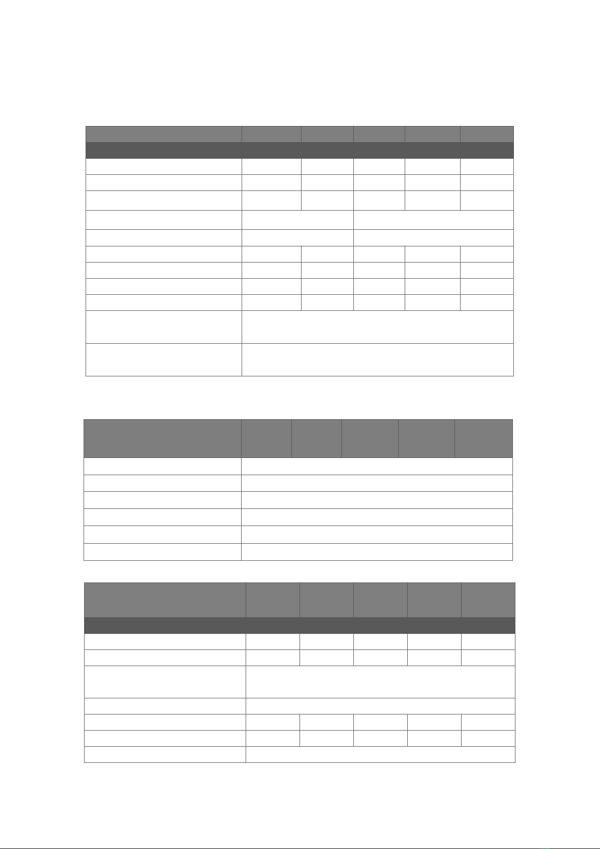
4. Technical Data ..............................................................................................................................7
4.1 PV Input (For KH Only) ..........................................................................................................7
4.2 Battery ...................................................................................................................................7
4.3 AC Output/Input ................................................................................................................... 7
4.4 EPS Output ............................................................................................................................ 8
4.5 Efficiency, Protection, Power consumption and Standard ...................................................8
4.6 General Data ......................................................................................................................... 9
5. Installation ...................................................................................................................................10
5.1 Check for Physical Damage .................................................................................................10
5.2 Packing List ..........................................................................................................................10
5.3 Mounting ............................................................................................................................ 11
6. Electrical Connection ................................................................................................................ 14
6.1 PV Connection (For KH Only) ..............................................................................................14
6.2 Battery Connection .............................................................................................................16
6.3 AC Connection .................................................................................................................... 17
6.4 Earth Connection ................................................................................................................ 20
6.5 Electrical Connection .......................................................................................................... 21
6.6 EPS Connection (Non-parallel State) .................................................................................. 31
6.7 System Connection Diagrams ............................................................................................. 33
7. Firmware Upgrading ..................................................................................................................34
8. Operation .................................................................................................................................... 35
8.1 Control Panel .......................................................................................................................35
8.2 Function Tree ...................................................................................................................... 36
9. Maintenance ............................................................................................................................... 37
9.1 Alarm List ............................................................................................................................ 37
9.2 Troubleshooting and Routine Maintenance .......................................................................43
10. Decommissioning .................................................................................................................... 44
10.1 Dismantling the Inverter ...................................................................................................44
10.2 Packaging .......................................................................................................................... 44
10.3 Storage and Transportation .............................................................................................. 44

1
1. Notes on This Manual
1.1 Scope of Validity
This manual describes the assembly, installation, commissioning, maintenance and troubleshooting of
the following model(s) of Fox ESS products:
KH7, KH8, KH9, KH10, KH10.5
KA7, KA8, KA9, KA10, KA10.5
Note: Please keep this manual where it will be accessible at all times.
1.2 Target Group
This manual is for qualified electricians. The tasks described in this manual only can be performed by
qualified electricians.
1.3 Symbols Used
The following types of safety instructions and general information appear in this document as described
below:
Danger!
“Danger” indicates a hazardous situation which, if not avoided, will result in death or
serious injury.
Warning!
“Warning” indicates a hazardous situation which, if not avoided, could result in death or
serious injury.
Caution!
“Caution” indicates a hazardous situation which, if not avoided, could result in minor or
moderate injury.
Note!
“Note” provides important tips and guidance.
This section explains the symbols shown on the inverter and on the type label:
Symbols
Explanation
Symbol Explanation CE mark. The inverter complies with the requirements of the
applicable CE guidelines.
This mark indicates compound UK product safety certification requirements.
Beware of hot surface. The inverter can become hot during operation. Avoid contact
during operation.
Danger of high voltages.
Danger to life due to high voltages in the inverter!

2
Danger.
Risk of electric shock!
Danger to life due to high voltage.
There is residual voltage in the inverter which needs 5 min to discharge.
Wait 5 min before you open the upper lid or the DC lid.
Read the manual.
Product should not be disposed as household waste.
PE conductor terminal.
2. Safety
2.1 Appropriate Usage
KH/KA series inverters are designed and tested in accordance with international safety requirements.
However, certain safety precautions must be taken when installing and operating this inverter. The
installer must read and follow all instructions, cautions and warnings in this installation manual.
-All operations including transport, installation, start-up and maintenance, must be carried out by
qualified, trained personnel.
-The electrical installation & maintenance of the inverter shall be conducted by a licensed
electrician and shall comply with local wiring rules and regulations.
-Before installation, check the unit to ensure it is free of any transport or handling damage, which
could affect insulation integrity or safety clearances. Choose the installation location carefully
and adhere to specified cooling requirements. Unauthorized removal of necessary protections,
improper use, incorrect installation and operation may lead to serious safety and shock hazards
or equipment damage.
-Before connecting the inverter to the power distribution grid, contact the local power distribution
grid company to get appropriate approvals. This connection must be made only by qualified
technical personnel.
-Do not install the equipment in adverse environmental conditions such as in close proximity to
flammable or explosive substances; in a corrosive or desert environment; where there is
exposure to extreme high or low temperatures; or where humidity is high.
-Do not use the equipment when the safety devices do not work or are disabled.
-Use personal protective equipment, including gloves and eye protection during the installation.
-Inform the manufacturer about non-standard installation conditions.
-Do not use the equipment if any operating anomalies are found. Avoid temporary repairs.
-All repairs should be carried out using only approved spare parts, which must be installed in
accordance with their intended use and by a licensed contractor or authorized Fox ESS service
representative.

3
-Liabilities arising from commercial components are delegated to their respective manufacturers.
-Any time the inverter has been disconnected from the public network, please be extremely
cautious as some components can retain charge sufficient to create a shock hazard. Prior to
touching any part of the inverter please ensure surfaces and equipment are under touch safe
temperatures and voltage potentials before proceeding.
2.2 PE Connection and Leakage Current
PV System Residual Current Factors
-
In every PV installation, several elements contribute to the current leakage to protective earth (PE).
these elements can be divided into two main types.
-
Capacitive discharge current - Discharge current is generated mainly by the parasitic capacitance of
the PV modules to PE. The module type, the environmental conditions (rain, humidity) and even the
distance of the modules from the roof can effect the discharge current. Other factors that may
contribute to the parasitic capacitance are the inverter’s internal capacitance to PE and external
protection elements such as lighting protection.
-
During operation, the DC bus is connected to the alternating current grid via the inverter. Thus, a
portion of the alternating voltage amplitude arrives at the DC bus. The fluctuating voltage constantly
changes the charge state of the parasitic PV capacitor (i.e capacitance to PE). This is associated
with a displacement current, which is proportional to the capacitance and the applied voltage
amplitude.
-
Residual current - if there is a fault, such as defective insulation, where an energized cable comes
into contact with a grounded person, an additional current flows, known as a residual current.
Residual Current Device (RCD)
-
All Fox ESS inverters incorporate a certified internal RCD (Residual Current Device) to protect
against possible electrocution in case of a malfunction of the PV array, cables or inverter (DC). The
RCD in the Fox ESS inverter can detect leakage on the DC side. There are 2 trip thresholds for the
RCD as required by the DIN VDE 0126-1-1 standard. A low threshold is used to protect against
rapid changes in leakage typical of direct contact by people. A higher threshold is used for slowly
rising leakage currents, to limit the current in grounding conductors for the safety. The default value
for higher speed personal protection is 30mA, and 300mA per unit for lower speed fire safety.
Installation and Selection of an External RCD device
-
An external RCD is required in some countries. The installer must check which type of RCD is
required by the specific local electric codes. Installation of an RCD must always be conducted in
accordance with local codes and standards. Fox ESS recommends the use of a type-A RCD.
Unless a lower value is required by the specific local electric codes, Fox ESS suggests an RCD
value between 100mA and 300mA.
-
In installations where the local electric code requires an RCD with a lower leakage setting, the
discharge current might result in nuisance tripping of the external RCD. The following steps are
recommended to avoid nuisance tripping of the external RCD:
1. Selecting the appropriate RCD is important for correct operation of the installation. An RCD with a
rating of 30mA may actually trip at a leakage as 15mA (according to IEC 61008). High quality RCDs will
typically trip at a value closer to their rating.
2. Configure the trip current of the inverter’ internal RCD to a lower value than the trip current of the
external RCD. The internal RCD will trip if the current is higher than the allowed current, but because the
internal inverter RCD automatically resets when the residual currents are low it saves the manual reset.

4
2.3 Surge Protection Devices (SPDs) for PV Installation
WARNING!
Over-voltage protection with surge arresters should be provided when the PV power system is installed.
The grid connected inverter is not fitted with SPDs in both PV input side and mains side.
Lightning will cause damage either from a direct strike or from surges due to a nearby strike.
Induced surges are the most likely cause of lightning damage in majority or installations, especially in
rural areas where electricity is usually provided by long overhead lines. Surges may impact on both the
PV array conduction and the AC cables leading to the building. Specialists in lightning protection should
be consulted during the end use application. Using appropriate external lightning protection, the effect of
a direct lightning strike into a building can be mitigated in a controlled way, and the lightning current can
be discharged into the ground.
Installation of SPDs to protect the inverter against mechanical damage and excessive stress include a
surge arrester in case of a building with external lightning protection system (LPS) when separation
distance is kept. To protect the DC system, surge suppression device (SPD type2) should be fitted at the
inverter end of the DC cabling and at the array located between the inverter and the PV generator, if the
voltage protection level (VP) of the surge arresters is greater than 1100V, an additional SPD type 3 is
required for surge protection for electrical devices.
To protect the AC system, surge suppression devices (SPD type2) should be fitted at the main incoming
point of AC supply (at the consumer’s cutout), located between the inverter and the meter/distribution
system; SPD (test impulse D1) for signal line according to EN 61632-1. All DC cables should be installed
to provide as short a run as possible, and positive and negative cables of the string or main DC supply
should be bundled together.
Avoiding the creation of loops in the system. This requirement for short runs and bundling includes any
associated earth bundling conductors. Spark gap devices are not suitable to be used in DC circuits once
conducting; they won’t stop conducting until the voltage across their terminals is typically below 30 volts.
3. Introduction
3.1 Basic Features
KH/KA series are high-quality inverters which can convert solar energy to AC energy and store energy
into battery. The inverter can be used to optimize self-consumption, store in the battery for future use or
feed-in to public grid. Work mode depends on PV energy and user’s preference.
• System advantages:
-
Advanced DSP control technology.
-
Utilizes the latest high-efficiency power component.
-
Advanced anti-islanding solutions.
-
IP65 protection level.
-
Max. Efficiency up to 97.8%. EU efficiency up to 97.4%. THD<3%.
-
Safety & Reliability: Transformerless design with software and hardware protection.
-
Export limitation (CT/Meter/DRM0/ESTOP).
-
Power factor regulation. Friendly HMI.

5
-
LED status indications.
-
LCD display technical data, human-machine interaction through four touch keys.
-
PC remote control.
•Work modes:
Work modes
Description
Self-use
(with PV Power)
Priority: load>battery>grid
The energy produced by the PV system is used to optimize
self-consumption. The excess energy is used to charge the batteries,
then exported to gird.
Self-use
(without PV Power)
When no PV supplied, battery will discharge for local loads firstly, and
grid will supply power when the battery capacity is not enough.
Feed in priority
Priority: load>grid>battery
In the case of the external generator, the power generated will be used
to supply the local loads firstly, then export to the public grid. The
redundant power will charge the battery.
EPS mode
When the grid is off, system will supply emergency power from PV or
battery to supply the home loads (Battery is necessary in EPS mode).
Note:Charging time is when the battery is charged within the set time range. The setting of charging time
can be used in the above three modes.
3.2 Dimensions

6
3.3 Terminals of inverter
Note: Only authorized personnel are permitted to set the connection.
Item
Description
Item
Description
A
PV1 (For KH Only)
I
PARALLEL 1
B
PV2 (For KH Only)
J
EPS
C
PV3 (For KH Only)
K
GRID
D
PV4
(For KH 9-10.5 Only)
L
PARALLEL 2
E
Battery Connector
M
DRM
F
BMS
N
Meter/CT/RS485
G
WiFi / 4G /USB
O
DC Switch
(For KH Only)
H
Waterproof Lock Valve
P
Grounding Screw

7
4. Technical Data
4.1 PV Input (For KH Only)
Model
KH7
KH8
KH9
KH10
KH10.5
PV
Max. recommended DC power [W]
10500
12000
13500
15000
15000
Max. DC voltage [V]
600
600
600
600
600
Nominal DC operating voltage [V]
360
360
360
360
360
Max. input current [A]
16/16/16*
16/16/16/16
Max. short circuit current [A]
20/20/20
20/20/20/20
MPPT voltage range [V]
80-500
80-500
80-500
80-500
80-500
Start-up voltage [V]
75
75
75
75
75
No. of MPP trackers
3
3
4
4
4
Strings per MPP tracker
1
1
1
1
1
Max. inverter backfeed current to
the array
0
DC disconnection switch
Optional
Note: * represents the maximum generating power of each pv string is limited to 3300 watts.
4.2 Battery
4.3 AC Output/Input
Model
KH7
KA7
KH8
KA8
KH9
KA9
KH10
KA10
KH10.5
KA10.5
AC OUTPUT
Nominal AC power [VA]
7000
8000
9000
10000
10500
Max. apparent AC power [VA]
7700
8800
9900
10500
10500
Rated grid voltage
(AC voltage range) [V]
220/230/240 (180 to 270)
Rated grid frequency [Hz]
50 / 60, ±5
Nominal AC current [A]
30.4
34.8
39.1
43.5
45.7
Max. AC current [A]
33.5
38.3
43.0
45.7
47.7
Inrush current [A]
9.6A@50us
Battery
KH7
KA7
KH8
KA8
KH9
KA9
KH10
KA10
KH10.5
KA10.5
Battery Type
Li-lon
Battery voltage range [V]
85-480
Recommended battery voltage [V]
300VDC
Max. Charge/ discharge current [A]
50
Communication interfaces
CAN/RS485
Reverse connect protection
YES

8
Max. output fault current [A]
130A@10us
Max. output over-current protection
[A]
91.4
Displacement power factor
0.8 leading to 0.8 lagging
Total harmonic distortion(THDi,
rated power)
<3%
AC INPUT
Max. AC power [VA]
14000
16000
18000
18000
18000
Rated grid voltage
(AC voltage range) [V]
220/230/240 (180 to 270)
Rated grid frequency [Hz]
50 / 60, ±5
Max. AC current [A]
60.9
69.6
78.3
78.3
78.3
4.4 EPS Output
Model
KH7
KA7
KH8
KA8
KH9
KA9
KH10
KA10
KH10.5
KA10.5
EPS OUTPUT (WITH BATTERY)
Max. apparent AC Power [VA]
7000
8000
9000
10000
10500
EPS rated voltage[V]
220/230/240
EPS rated frequency[Hz]
50/60
Max. EPS current [A]
31.8
36.4
40.9
45.5
47.7
EPS peak power [W]
10000, 60s
12000,60s
Switch time [s]
<20ms
Total harmonic distortion (THDv,
linear Load)
<2%
Parallel operation
Yes @max10PCS
4.5 Efficiency, Protection, Power consumption and Standard
Model
KH7
KA7
KH8
KA8
KH9
KA9
KH10
KA10
KH10.5
KA10.5
EFFICIENCY
MPPT efficiency
99.90%
99.90%
99.90%
99.90%
99.90%
Euro-efficiency
97.40%
97.40%
97.40%
97.40%
97.40%
Max. Efficiency
97.80%
97.80%
97.80%
97.80%
97.80%
Max. Battery charge efficiency(PV to
BAT)(@full load)
98.50%
98.50%
98.50%
98.50%
98.50%
Max. Battery charge/discharge
efficiency (BAT to AC)(@full load)
97.00%
97.00%
97.00%
97.00%
97.00%
PROTECTION
PV reverse polarity protection
YES
Battery reverse protection
YES
Anti-islanding protection
YES
Output short protection
YES

9
Leakage current protection
YES
Insulation Resistor Detection
YES
Over-current protection
/Over-temperature protection
YES
Over voltage category
III(AC side),II(DC side)
AC/DC surge protection
Type II/Type II
AFCI protection
optional
POWER CONSUMPATION
Standby consumption [W] (Idle)
<15
STANDARD
Safety
IEC62109-1/IEC62109-2/IEC62477-1
EMC
EN 61000-6-1 / EN 61000-6-2 / EN 61000-6-3
Certification
G99 /AS4777.2 / EN50549-1/ CEI 0-21 /NRS 097-2-1 and so on
4.6 General Data
DIMENSION AND WEIGHT
Dimensions (W*H*D) [mm]
450*527*208mm
Net weight/gross weight [kg]
29/33.5(KH), 26.4/30.9(KA)
Cooling concept
Natural
Topology
Non-isolated
Communication
Meter (optional), WIFI,4G (optional), DRM, USB,CT,RS485
LCD display
Backlight 16*4 character
ENVIRONMENT LIMIT
Installation
wall-mounted
Ingress protection
IP65 (for outdoor use)
Inverter operating temperature
range [°C]
-25…... +60 (derating at +45°C)
Storage/Operation relative humidity
0%-95% (without condensation)
Altitude [m]
<2000
Protective class
I
Storage temperature [°C]
-40…… +70
ldle mode
YES
Button
Capacitive touch sensor *4
Buzzer
1, inside (EPS & Earth fault)

10
5. Installation
5.1 Check for Physical Damage
Make sure the inverter is intact during transportation. If there is any visible damage, such as cracks,
please contact your dealer immediately.
5.2 Packing List
Open the package and take out the product, please check the accessories first. The packing list shown
as below.
N O P Q
Object
Quantity
Description
Object
Quantity
Description
A
1
Inverter
J
1
WiFi/LAN/4G (Optional)
B
1
Bracket
K
1
Meter (Optional)
C
6/8
PV connectors (Only for KH)
(3*positive, 3*negative) (KH 7-8)
(4*positive, 4*negative) (KH 9-10.5)
L
1
CT extension connector
D
6/8
PV pin contacts (Only for KH)
(3*positive, 3*negative) (KH 7-8)
(4*positive, 4*negative) (KH 9-10.5)
M
3
Hexagonal screws
E
2
AC connectors (1*EPS, 1*GRID)
N
2
Battery connectors
(1*positive, 1*negative)
F
6
Expansion tubes &
Expansion screws
O
2
Battery pin contacts
(1*positive, 1*negative)
G
1
Earth terminal
P
1
CT (with 10m cable)
H
1
Communication connector
Q
1
RJ45
I
1
Quick installation guide
I J K L M
A B C D
E F G H

11
5.3 Mounting
• Installation Precaution
Make sure the installation site meets the following conditions:
-
Not in direct sunlight.
-
Not in areas where highly flammable materials are stored.
-
Not in potential explosive areas.
-
Not in the cool air directly.
-
Not near the television antenna or antenna cable.
-
Not higher than altitude of about 2000m above sea level.
-
Not in environment of precipitation or humidity (> 95%).
-
Under good ventilation condition.
-
The ambient temperature in the range of -25°C to +60°C.
-
The slope of the wall should be within +5*.
-
The wall hanging the inverter should meet conditions below:
A. Solid brick/concrete, or strength equivalent mounting surface;
B. Inverter must be supported or strengthened if the wall's strength isn't enough (such as wooden wall,
the wall covered by thick layer of decoration).
Please avoid direct sunlight, rain exposure, snow laying up during installation and operation.
• Space Requirement
Position
Min Distance
Left
500mm
Right
500mm
Top
500mm
Bottom
500mm

12
• Mounting Steps
Tools required for installation:
-
Manual wrench;
-
Electric drill (drill bit set 8mm);
-
Crimping pliers;
-
Stripping pliers;
-
Screwdriver.
1. Fix the bracket on the wall
-
Choose the place you want to install the inverter. Place the bracket on the wall and mark the
position of the 6 holes from bracket.
-
Drill holes with electric drill, make sure the holes are at least 50mm deep and 8mm wide, and then
tighten the expansion tubes.

13
-
Insert the expansion tubes into the holes and tighten them. Install the bracket with the expansion
screws.
2. Match the inverter with wall bracket
-
Mount the inverter to the bracket. Secure the inverter with the M5 screw and washer.

14
6. Electrical Connection
6.1 PV Connection (For KH Only)
Step 1: PV String Connection
KH series inverters can be connected with 4-strings of PV modules. Please select suitable PV modules
with high reliability and quality. Open circuit voltage of module array connected should be less than 600V,
and operating voltage should be within the MPPT voltage range.
Note!
Please choose a suitable external DC switch if the inverter does not have a built-in DC switch.
Warning!
PV module voltage is very high and within a dangerous voltage range, please comply with the
electric safety rules when connecting.
Warning!
Please do not make PV positive or negative to ground!
Note!
PV modules: Please ensure they are the same type, have the same output and specifications,
are aligned identically, and are tilted to the same angle. In order to save cable and reduce DC
loss, we recommend installing the inverter as near to the PV modules as possible.

15
Step 2: PV Wiring
• Turn off the DC switch.
• Choose 12 AWG wire to connect the PV module.
• Trim 6mm of insulation from the wire end.
• Separate the DC connector (PV) as below.
Plug Pin contact cable nut
• Insert striped cable into pin contact and ensure all conductor strands are captured in the pin contact.
• Crimp pin contact by using a crimping plier. Put the pin contact with striped cable into the
corresponding crimping pliers and crimp the contact.
• Insert pin contact through the cable nut to assemble into back of the male or female plug. When you
feel or hear a “click” the pin contact assembly is seated correctly.
• Unlock the DC connector
- Use the specified wrench tool.
- When separating the DC + connector, push the tool down from the top.
- When separating the DC - connector, push the tool down from the bottom.
- Separate the connectors by hand.

16
6.2 Battery Connection
• Choose 8 AWG wire to connect the battery.
• Trim 6mm of insulation from the wire end.
• Separate the DC connector (battery) as below.
Plug Pin contact cable nut
• Insert striped cable into pin contact and ensure all conductor strands are captured in the pin contact.
• Crimp pin contact by using a crimping plier. Put the pin contact with striped cable into the
corresponding crimping pliers and crimp the contact.
• Insert pin contact through the cable nut to assemble into back of the male or female plug. When you
feel or hear a “click” the pin contact assembly is seated correctly.
• Unlock the DC connector
- Use the specified wrench tool.
- When separating the DC + connector, push the tool down from the top.
- When separating the DC - connector, push the tool down from the bottom.
- Separate the connectors by hand.

17
6.3 AC Connection
Step 1: AC String Connection
KH/KA series inverters are designed for single-phase grid. Per voltage range is 220/230/240V; frequency
is 50/60Hz. Other technical requests should comply with the requirement of the local public grid.
WARNING!
If you don’t use the EPS function or use on-grid power to charge the battery, the wiring
conduct core section can use 8-10mm². At the same time, you can choose 63A Micro-
Breaker.
A micro-breaker for max output over-current protection device shall be installed between
inverter and grid, and the current of the protection device is referred to the table above,
any load SHOULD NOT be connected with the inverter directly.
Step 2: AC Wiring
• Check the grid voltage and compare with the permitted voltage range (refer to technical data).
• Disconnect the circuit-breaker from all the phases and secure against re-connection.
• Trim the wires:
- Trim all the wires to 52.5mm and the PE wire to 55mm.
- Use the crimping pliers to trim 12mm of insulation from all wire ends as below.
Note: Please refer to local cable type and color for actual installation.
Power (kW)
7.0
8.0
9.0
10.0
10.5
Cable (ON-GRID)
13.0mm²
13.0mm²
13.0mm²
13.0mm²
13.0mm²
Cable (EPS)
8.0mm²
8.0mm²
8.0mm²
8.0mm²
8.0mm²
Micro-Breaker
100A
100A
100A
100A
100A
L: Brown/Red Wire
N: Blue/Black Wire
PE: Yellow & Green Wire
This manual suits for next models
11
Table of contents
Other FoxESS Inverter manuals

FoxESS
FoxESS T Series User manual

FoxESS
FoxESS LV5200 User manual

FoxESS
FoxESS T Series User manual

FoxESS
FoxESS H3 Series User manual

FoxESS
FoxESS R Series User manual

FoxESS
FoxESS F-G2 Series User manual

FoxESS
FoxESS E Series User manual

FoxESS
FoxESS US Series User manual

FoxESS
FoxESS S700-G2 User manual

FoxESS
FoxESS H1 Series User manual
Popular Inverter manuals by other brands

Tripp Lite
Tripp Lite PowerVerter RV Inverter/Charger RV2012OEM Specifications

ESDEC
ESDEC Clickfit Evo manual

Tripp Lite
Tripp Lite PowerVerter RV1012UL Owner's manual addendum

APsystems
APsystems DS3D user manual

LS ELECTRIC
LS ELECTRIC SV-iS7 Series user manual

FRONIUS
FRONIUS Galvo 208-240 1.5-1 operating instructions