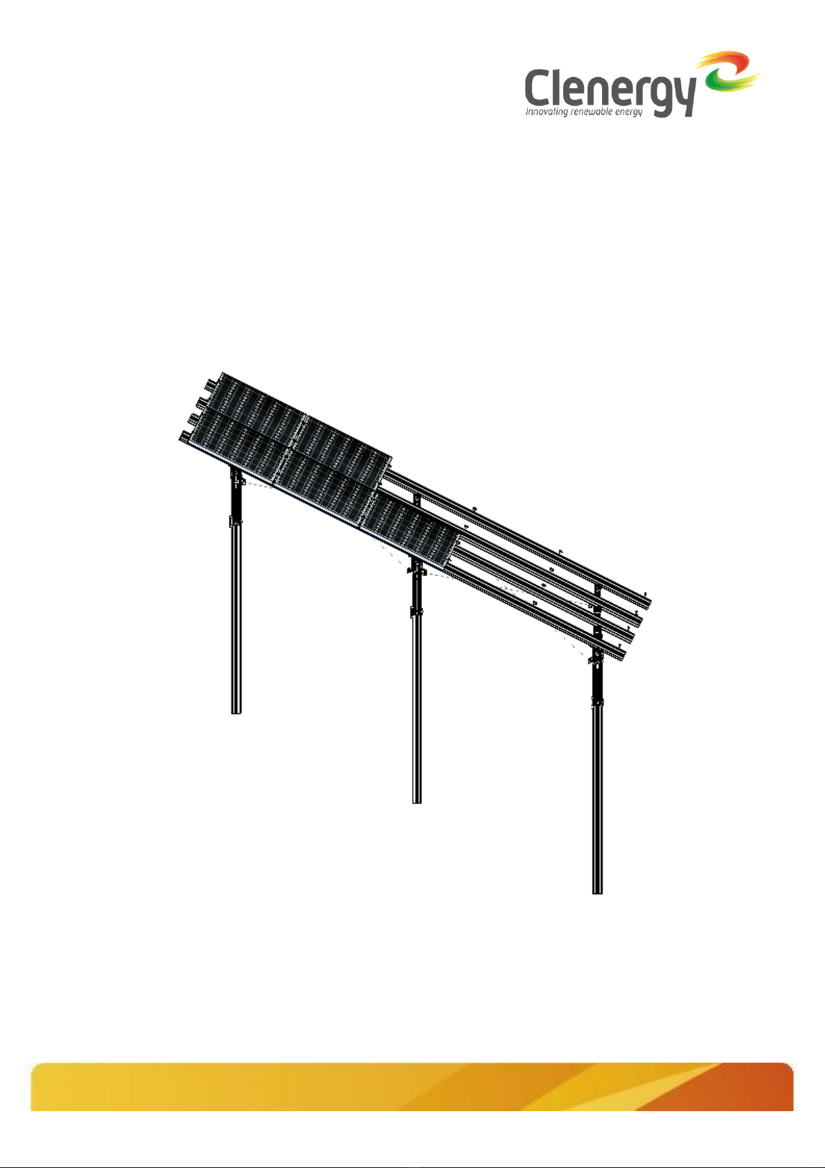
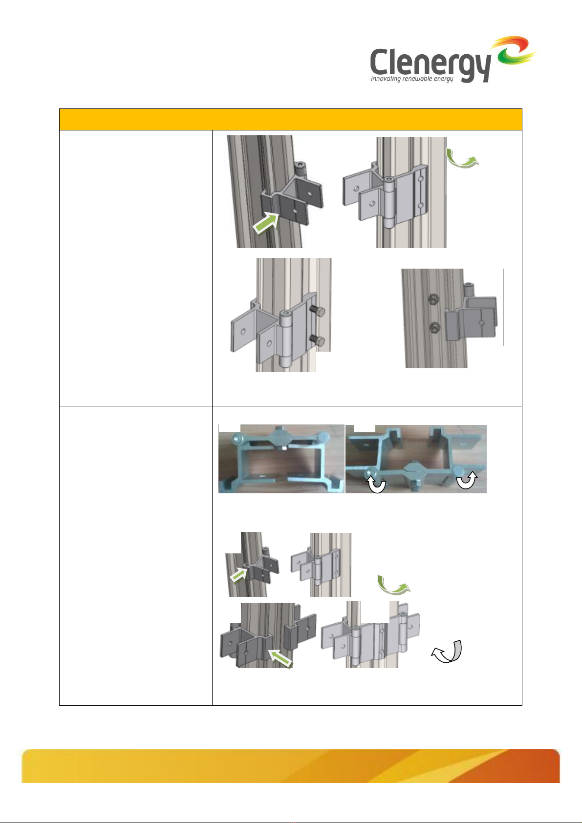
Clenergy PV-ezRack SolarTerrace II-F User manual
Other Clenergy Inverter manuals

Clenergy
Clenergy PV-ezRack Ascent User manual

Clenergy
Clenergy PV-ezRack SolarRoof Technical manual

Clenergy
Clenergy PV-ezRack SolarRoof User manual

Clenergy
Clenergy PV-ezRack SolarTerrace II Technical manual

Clenergy
Clenergy PV-ezRack User manual

Clenergy
Clenergy SPH15 User manual

Clenergy
Clenergy PV-ezRack SolarFloating I User manual

Clenergy
Clenergy PV-ezRack User manual

Clenergy
Clenergy PV-ezRack SolarRoof Technical manual

Clenergy
Clenergy PV-ezRack Grounding system Technical manual

Clenergy
Clenergy PV-ezRack SolarRoof User manual

Clenergy
Clenergy SPH50 User manual

Clenergy
Clenergy PV-ezRack SolarRoof Isolator Shade User manual

Clenergy
Clenergy PV-ezRack SolarRoof Technical manual

Clenergy
Clenergy PV-ezRack SolarRoof ER-TL-10/15 User manual

Clenergy
Clenergy PV-ezRack PostMount 4-A User manual

Clenergy
Clenergy PostMount 6-A User manual

Clenergy
Clenergy PV-ezRack Commercial Tilt User manual

Clenergy
Clenergy PV-ezRack SolarTerrace Eco User manual