PTL PTL-Stop-n-Go PTL-TYPE-1 User manual
PTL-STOP-N-GO OPERATIONS MANUAL 1
PTL-Stop-n-Go™Operations and
Maintenance Manual. PTL-TYPE-1
Your Portable Traffic Lights are lightweight traffic lights. As such correct operation for
Set-up and Take-down procedure is essential. Please ensure this manual is read and
understood before attempting to operate the Data Signs’ Portable Traffic Lights (PTL).
Set-up and Maintenance requirements of the PTL are covered by this Manual.
CAUTION:
The Data Sign Portable Traffic Lights should
only be operated by qualified traffic managers.
If you have hired out this PTL, contact the Hire
Company for assistance.
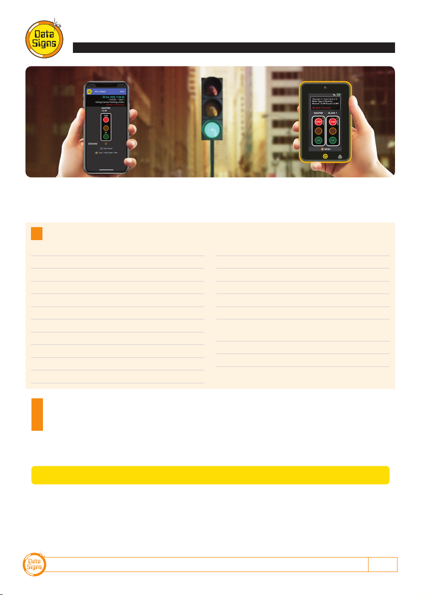
The PTL-Stop-n-Go™ is used to control localized
vehicular traffic flow as a safer substitute for STOP/
SLOW (lollipop) signs. It does not incorporate features
such as solar powered operation operation or remote
DS-Live monitoring, vehicle detection and auto-timing.
It is powered by a LiPo maintenance free battery that
needs to be recharged at the end of the day. It is not
intended to be left unattended on site and can only
be operated via the Remote Control which places a
safe distance between the actual Traffic Light and the
operator.
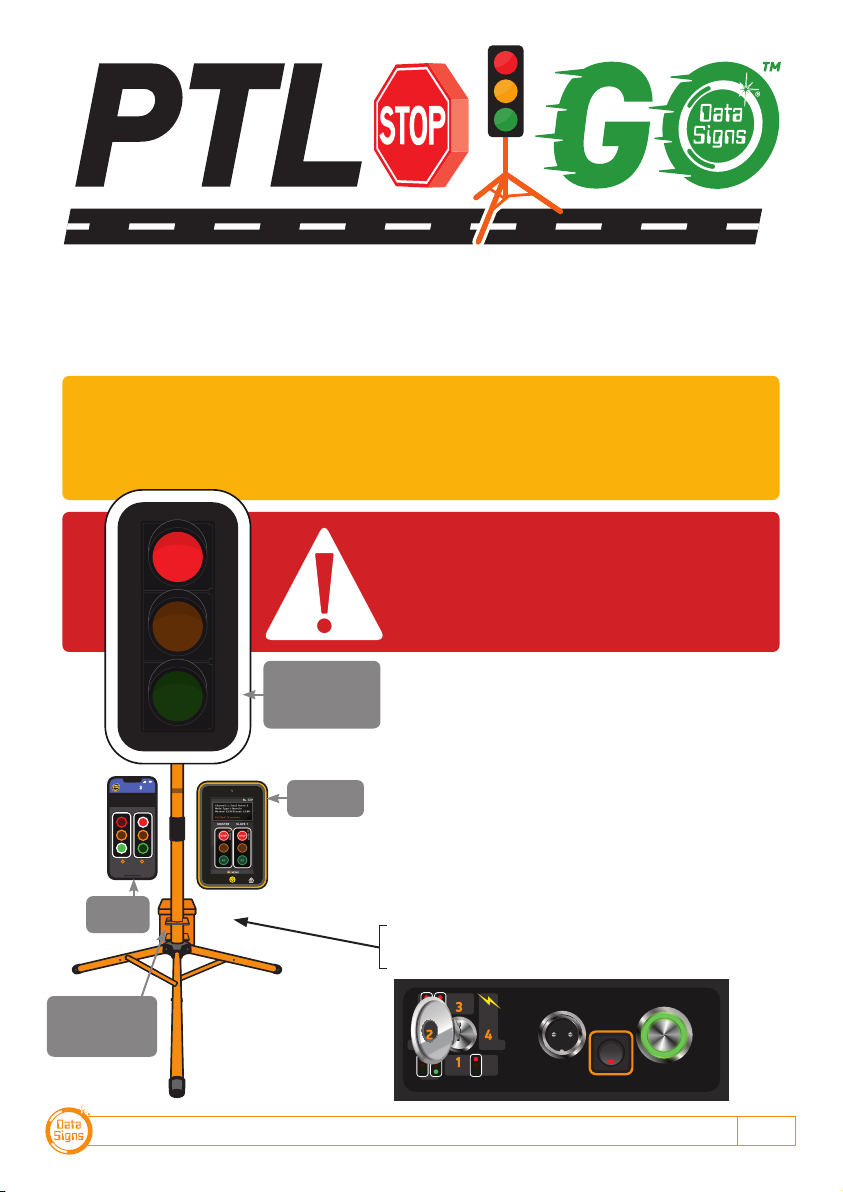
An overview of the layout of the PTL-Stop-n-Go™
equipment is provided here.
10:14a m 4G
GO
STOPSTOP
GO
DEMAND
MENU
Shut Down
EXITPTL PTLSG
MASTER SLAVE
LAB 0014ED Issue 1
POWER SET CHANNEL
/STATUS
Switch on
aſter plugging
connector in.
PLANT
GAT E
CONNECTED
TO MASTER PTL
SHUTTLE
SL AV E
Showing optional
target board.
Target boards are
mandatory for NSW.
Long Range
Remote
Bluetooth
Remote
Battery, Charger,
Optional Remote
and USB Charger.
DATA SIGNS AUSTRALIA PTY LTD
2
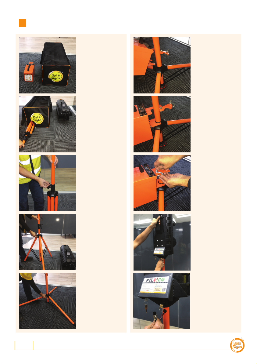
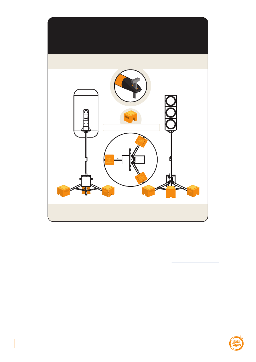
Installation - Setting Up for Operation
Step 1:
Step 8:
Lock the holding
bracket with a
padlock or similar.
Step 4:
Pull out spring pin
and slide the tripod
legs down to the
first hole.
Step 3:
Loosen locking tab,
lift the post to the
pin-hole & place
pin.
Step 7:
Twist and fit around
the post.
Step 6:
Fit Battery Box.
Step 2:
Unpack the light
and take out the
stand.
Step 9:
To fit the lights,
pull spring pin and
lower onto post.
Release the pin into
the fixing hole.
Step 5:
Release the spring
pin and ensure the
tripod is locked.
Step 10:
Line up and
Connect the power
connector to the
Socket.
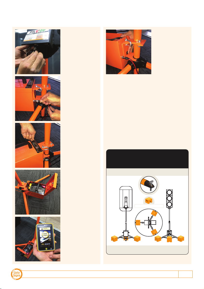
PTL-STOP-N-GO OPERATIONS MANUAL 3
Step 12:
Now do the same
for the Battery
Pack.
Step 11:
Push in and Screw
Nut to lock it in.
Step 15:
PTL Remote or
Bluetooth remote
taken out.
Step 16:
Press the Power
switch to the ON
position, the LED
will come on.
Refer to manual to
operate lights using
Remote.
Step 14:
Open Lid and
remove optional
PTL Remote if
supplied.
Step 13:
Twist the lock Tabs
to open the LID.
To dismantle the unit use reverse process.
RATING FOR 20M/SECOND (72 Kph)
WIND LOADING
Note: Your PTL has a TILT sensor which will indicate on the PTL-Remote if the
unit is tilted by more than 20 degrees (i.e. It has fallen over).
The PTL is fitted with Peg Feet.
Where suitable you can secure it with pegs instead of weights.
Optional 20Kg Ballasts shown
DATA SIGNS AUSTRALIA PTY LTD
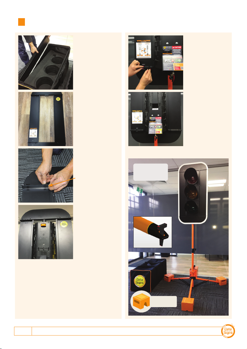
4
Step 1:
Remove the four
parts from the side
pocket.
Step 4:
Place the
assembled sections
over the lamps as
shown
Step 3:
Align and assemble
top section to the 2
sides.
Line up tick marks.
Step 7:Step 2:
Assemble this way.
Step 6:
Now, assemble the
bottom panel as
shown.
Installation - Target Board Setup (if optioned)
CHECK BALLAST
REQUIREMENT AT
END OF MANUAL
Optional 20Kg
Ballasts shown
PTL-STOP-N-GO OPERATIONS MANUAL 5
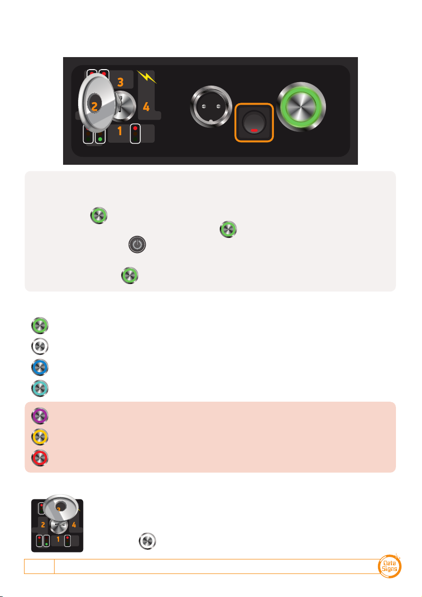
MODE SELECT:
For Security and Safety, this is done via the Key-Switch located on the back of the PTL.
There are 4 modes of operation, these are explained as per below and in more detail later:
Key Position 1 (fully anti clockwise) Gating Mode - Single Use
Key Position 2 +1 to the right Shuttle Mode - Master
Key Position 3 +2 to the right Plant Crossing Mode - Master
Key Position 4 (fully clockwise) Slave Mode - Slave
Selecting Operation Mode & Switching Lights On 5
Startup 6
PTL Bluetooth Remote 7
Long-Range PTL Remote Controller 9
Setting the RF Channel on the Remote Control 9
Flashing Yellow Light 10
Self-Test 10
Gating Control Mode 11
Shuttle Mode – Single Lane Usage 12
Plant-Mode 2-Way Traffic 14
Battery Charging 16
Wireless Link (RF) Explained 16
Fault Conditions 16
Troubleshooting Guide 17
The SD Card 17
Maintenance 17
Glossary of Terms and Abbreviations 18
Appendix A: Cycle and Phase Intervals for 19
Shuttle and Plant Crossing& Plant Crossing
Appendix B: All-Red Time Chart 19
Wind Loading, Ballast Requirements 20
Contents
PTL-Stop-n-Go™PTL-TYPE-1
Bluetooth Remote Long-Range PTL Remote
This QuickStart Guide covers the PTL TYPE-1 Operation as per QLD MRTS264, TSI-SP-049-050-062, Australian Standards
AS-4191:2015 and Various State Authority requirements.
Ensure the units are setup as described in the first section of this booklet. This User Manual applies to Controllers operating on
firmware 06.00.XX or later.
Selecting operating mode and
switching
lights on.
Once mode is selected, remove the Key and keep in a safe place.
DATA SIGNS AUSTRALIA PTY LTD
6
The following steps are used if the Data Signs Long-Range Remote is used. Not necessary when using a
BlueTooth Remote.
1. Switch on the PTL Remote and see what channel it is set on.
Press the BUTTON once for each channel.
i.e. If the Remote is set to channel 2, press the BUTTON twice.
2. Press and HOLD the button on the Remote to start the PTL operating as per the MODE
selected by the Key-Switch.
Note: The Key-Switch and BUTTON are disabled once the PTL Lights are operating.
BUTTON STATUS LIGHT MEANING:
LAB 0014ED Issue 1
POWER SET CHANNEL
/STATUS
Switch on
aſter plugging
connector in.
PLANT
GATE
CONNECTED
TO MASTER PTL
SHUTTLE
SL AVE
Power On
Channel number.
1 flash = Channel 1, 2 flashes = Channel 2 etc.
Remote is connected to Master. IF this PTL is set as a Slave then BLUE means it is
connected to the Master.
Master & Slave are connected.
RF Link signal is weak. (Ensure line of sight with other PTL or change RF Channel)
Battery low, replace or charge battery
Fault condition, check on Remote for what the fault is.
(Cycle the power to clear the fault)
PLANT
GAT E
CONNECTED
TO MASTER PTL
SHUTTLE
SL AVE
SLAVE MODE / POSITION 4:
In this mode the PTL is under the control of the Master PTL.
It must be set to the same RF Channel as the Master PTL to operate.
The RF Channel is set as per above instructions and indicated by the number of White
Pulses on the BUTTON.
SWITCHING THE PTL ON:
When the power connectors are plugged in and the power switch is turned ON as per set-up procedure:
PTL-STOP-N-GO OPERATIONS MANUAL 7
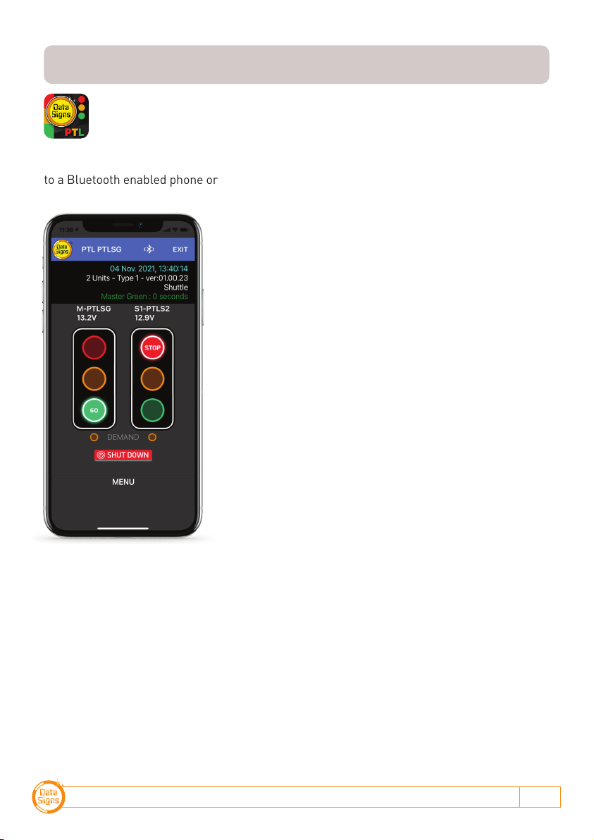
The PTL Stop-n-Go™ Lights are fitted with a Bluetooth interface. This allows for connection
to a Bluetooth enabled phone or device.
1. Press the PTL Connect Icon. If it is the first time
enter the password (The default is 123456).
2. The Password is set using the PTL Stop-n-Go™ app.
This is covered on page 17.
3. Press Scan on the screen. Your device will now look
for the Bluetooth in the PTL controller.
4. Once the PTL is found the Logo and the PTL Serial
number will appear on the screen. Press the Logo.
The screen will then Prompt for the Password. Enter
this and press the Connect button. Your device will
now show the Remote operation screen.
(Note next time you activate your device to use as a
Remote, a password is not needed as it is now stored in
the device.)
Note, the light and any other actions work by taping the
screen. i.e. to change to a RED light, tap the Red light on
the screen.
Status screen.
The top line shows date and time, if this count is active
your device is connected.
The second line shown how many units are connected.
i.e. 1 Unit(s) - Type 1
The third line shows the Mode the PTL is currently as
operating, i.e. Gating Control
The fourth Line show the remaining time for the phase.
Bluetooth Remote
For use with Bluetooth enabled devices.
Data Signs can supply a fully configured, DEDICATED Bluetooth device as part of
your PTL-Stop-n-Go purchase.

DATA SIGNS AUSTRALIA PTY LTD
8
THE MAIN SCREEN
The Main screen will display the lights for the Master on the left and the Slave on the right
side of the screen. If in Gating mode only one PTL will be visible.
The Battery voltage of the PTL is shown below each PTL Master or Slave Label.
An Alarm will indicate if the battery reaches a too low level.
Tap the STOP Red lamp to change to Red if the light is on Green
Same operation applies for GO Green lamp.
SHUT DOWN
To Shut the lights down or Start them
up again from the MENU, tap the Shut
Down button and confirm by pressing
Yes.
The Light(s) will go blank, or start up
whichever the case might be.
s
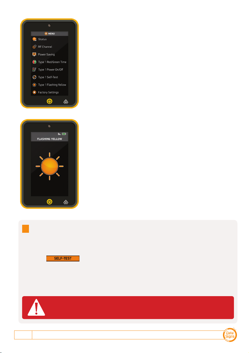
FLASHING YELLOW LIGHT
You can set the Lights to Flash
Yellow only.
This might serve as a caution or
warning lights.
s
For a more descriptive manual, please scan this QR code:
(datasigns.com.au/documents/HelpDesk/Local-Bluetooth-Connect-Manual.pdf)
PTL-STOP-N-GO OPERATIONS MANUAL 9
Note: The Actual PTL-Stop-n-Go must be set to the same RF Channel.
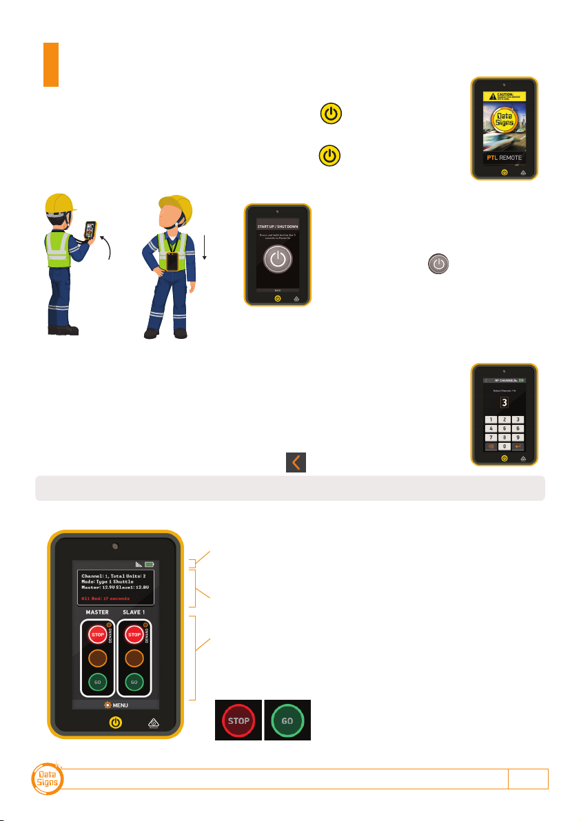
To switch the long-range PTL-Remote on, press the button.
The unit will beep twice and the startup screen will appear after a few seconds.
To SHUTDOWN the PTL-Remote, press and hold the
button.
The unit will give a long beep and shutdown.
LIGHTS STARTUP
Select Type 1 Power On/Off from the
menu.
To startup press the button on the
screen for 5 seconds.
In shutdown state, the lights are disabled.
Startup and PTL operation using the
Long-Range Remote
SETTING THE RF CHANNEL ON THE REMOTE CONTROL.
To set the RF Channel on the Remote Control, follow these instructions.
1. Press the MENU button on the bottom of the screen to go to settings.
2. Press the RF Channel option.
3. Enter the new channel number.
4. Enter the power, i.e. set to 30%.
5. To re-start normal operation, press the button.
RAISE
TO WAKE
LOWER
TO SLEEP
CHANGE
LIGHTS
The top of the screen shows the battery level of the PTL
Remote. The signal strength between the Master and the
PTL Remote.
The status box shows current operational type and the
countdown timer for the currently displaying Lights.
The main section of the screen shows the state of the
connected PTL's.
Press the Green or Red Light buttons on the main section of
the screen to change the lights being displayed.
DATA SIGNS AUSTRALIA PTY LTD
10
Use the MENU button on the bottom of the screen to open
the SETTINGS menu screen.
From the menu screen, Startup or Shutdown the connected
PTL units.
The RF Channel as well as the STATUS is also selected from
this menu.
Press BACK to return to normal operating mode.
Note: Self test is only possible when lights are not operating (or prior to Startup)
When the butto button is pressed, the following sequence is run on the PTL
Compact to test the aspects, on any connected units:
Green signal, yellow signal, red signal and blank for 0.2 seconds.
Note: the Red and Green Times are reset to the default times of Green = 1 Second, Red = 1
Second.
Self-Test
It is advisable that the self-test not be carried out while the PTL's are setup
on the roadway.
FLASHING YELLOW LIGHT.
You can set the Lights to Flash Yellow only.
This might serve as a caution or warning lights.
Note: The light(s) must be on RED to enable the Menu item to
switch on Flashing Yellow.
Roadworks
Site
One-Way Road
PTL-STOP-N-GO OPERATIONS MANUAL 11
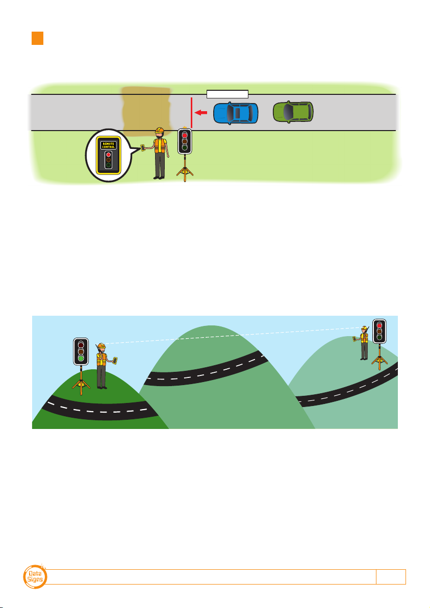
Gating Control Mode
Single PTL unit use only.
Gating Control is used to control the flow of traffic from a single traffic flow direction only.
Gating control can also be used with 2 PTL units operating independently by two traffic
operators using a Walky-Talky to communicate with each other.
Note: If using 2 PTL's in Gating Mode, each PTL must be set on its own unique channel
number as there in NO radio-link communication between each unit and also to eliminate
risk of possible interference between the two units.
In this mode, the line of sight or distance limit does not apply.
Note: Two independent PTL Remotes and operators are required for this operation.
Roadworks
Site
One-Way Road
Normal line-of-sight operation not used
in this setup configuration.
Two-way radios used between traffic
management operators.

DATA SIGNS AUSTRALIA PTY LTD
12
Shuttle Mode – Single Lane Usage
Shuttle Control is a form of traffic control used where a portion of the roadway is closed
so that only a single lane can be used alternatively by traffic from opposite directions.
Only one Traffic Light unit can show the Green signal phase at any time; either the Master
or the Slave. The diagram below illustrates the traffic control scenario where Shuttle
control would typically be used.
Note: This diagram should not be used as a guideline for setting up a roadwork site, it is
provided as an example only.
Each PTL unit will go to the Green signal phase in turn. See timing diagram later in this
manual.
Shuttle Control is active while the key-switch on the Master PTL is in the SHUTTLE
position. Operating mode using Shuttle Control is described in more detail on the
following page.
ROADWORKS
SITE
= Rear Flashing Beacon
SHUTTLE CONTROL
These illustrations are intended to outline the different modes which can be used with Data Signs Portable Traffic Lights and should not be used as examples or guidelines on how to setup a
roadwork site − Separate documentation is available for these purposes. Copyright © 2021 Data Signs Pty Ltd. All rights reserved.
Key-switch set to
SHUTTLE position
on Master unit.
Key-switch set to
SLAVE position
on other unit.

PTL-STOP-N-GO OPERATIONS MANUAL 13
SHUTTLE MODE.
A demand for Green or Red signal on the Master or Slave is entered on the Remote
Control unit. For Shuttle Control, on start-up, both the Master and Slave will rest on
Red until a demand for Green is entered.
To enter a demand for either Red or Green, press
the STOP or GO buttons on the Remote Control.
The DEMAND LED is activated indicating a demand
for either the Master or Slave.
To enter a demand for Green for either the Master
or the Slave, both Master and Slave MUST be at
Red. Then the Green can be selected.
REAR BEACON LAMP:
The Beacon Lamps mounted behind the Traffic Lights flash on each unit when the Red
Lights are ON. This is useful for the operator to know the Lamp is on RED phase when
behind the actual lights. It also acts as a Caution indicator for Vehicles.

DATA SIGNS AUSTRALIA PTY LTD
14
Plant Crossing Mode – 2-Way Traffic
Plant-Crossing control is used to enable both directions of traffic flow along a roadway to
be simultaneously stopped, e.g. to allow road construction vehicles (or pedestrians in a
controlled environment) to cross. The diagram below illustrates Plant-Crossing control
usage.
Note: This diagram should not be used as a guideline for setting up a roadwork site, it is only
provided as an example.
Plant-Crossing Control is active while the key-switch is in the PLANT CROSSING position
on the Master PTL.
REAR BEACON LAMP
The Beacon Lamps mounted behind the Traffic Lights flash on each unit when the Red
lights are ON. This acts as a visual indicator to the Plant (vehicles) Crossing the road that
it is safe to do so.
SIDE / HAUL
ROAD
= Rear Flashing Beacon
PLANT-CROSSING CONTROL
Both units show the same signal phase.
These illustrations are intended to outline the different modes which can be used with Data Signs Portable Traffic Lights and should not be used as examples or guidelines on how to setup a
roadwork site − Separate documentation is available for these purposes. Copyright © 2021 Data Signs Pty Ltd. All rights reserved.
Key-switch set to
SLAVE position
on other unit.
Key-switch set to
PLANT position.

PTL-STOP-N-GO OPERATIONS MANUAL 15
PLANT CROSSING MODE.
On start-up, both the Master and Slave will rest on Green signal phase for Plant-Crossing
Control until a demand for Red signal is entered by the operator.
The operator can enter a demand for Red signal using either STOP buttons on the Remote.
Both the Master and Slave units will then cycle to Yellow and the Red signal phase.
To change back to Green signal, either the Master: GO or Slave: GO button is pressed.
Plant-Crossing Control example:
1. Both the Master and Slave are on Green.
2. Either the Master: STOP or Slave: STOP buttons
can be pressed on the PTL Remote.
3. To resume Traffic flow, press either GO button.

DATA SIGNS AUSTRALIA PTY LTD
16
Each Traffic Light is fitted with an RF Communications module. This will provide Wireless
Radio (RF) communication between the PTL units; however, the units still need to be
positioned in line-of-sight to each other.
The maximum distance between the Master and Slave PTL's is about 800m, depending on
surrounding environment.
The radio link module fitted to the PTL unit communicates on one of eight channels. This
must be set to the same channel on each unit to maintain wireless communication. This
applies to the Master, Slave, and the Long-Range Remote Control.
Note: The Bluetooth remote does not operate on a RF channel.
Radio Link Operation
If the radio link between the Master and a Slave unit is disrupted for a continuous 2 second
period (the default time) all units will revert to red lights and the system will restart, however
if the radio link is lost for more than 1 minute the, system will restart in Startup Mode and all
lights will be blank.
Signal Strength
The long range PTL-Remote Control will display the signal strength of the Master Controller
to the PTL Remote as a Graphic symbol in the top right corner on the display.
Wireless Link (RF) Explained
Battery Charging
If any fault conditions occur as discussed throughout this document, the Fault is displayed
on the Remote and if critical the Lights will go to RED. When the fault is cleared, normal
operation is resumed
Fault Conditions
TO CHARGE BATTERY
S
i
g
n
s
D
a
t
a
S
i
g
n
s
D
a
t
a
Plug in the charger to the
Mains Power.
To Charge the PTL-Remote,
turn switch to ON.

PTL-STOP-N-GO OPERATIONS MANUAL 17
This section contains some tips on handling some of the issues that
may arise when using the Traffic Lights. If you cannot resolve the issue
you are experiencing using the information below, please contact Data
Signs on the Help Desk at datasigns.com.au/help.
Turning the Controller On
If the POWER light does not come on when the switch is turned ON:
• Check that the power connector is inserted properly.
• Check the fuse of the Controller that is inside the light housing (behind the Green
lamp) and inside the battery box.
• Check that the battery voltage is above 11.2 Volts.
Radio Wireless Link failure
If the radio wireless link fails regularly, try changing the Channel set on both lights, as some
interference may be occurring on the operating channel.
Check that the units are situated as visible to each other. i.e. line of sight. Hills or buildings
are obstructions and will cause radio link difficulties or failures.
Lights Not Working
Check the connections on the controller or the lights.
If you need to ship the Controller or parts back to Data Signs for repair, contact the
Help-Desk at datasigns.com.au/help
The PTL Controller is fitted with a SD card.
This is used for Software upgrades and also to set the PIN for
Bluetooth devices when used as Remotes.
To set or change the Bluetooth PIN.
1. Go to datasigns.com.au
2. From the Apps tab, download the PTL-Stop-n-Go™ program.
3. Set the pin and store to the SD Card, then plug back into
controller.
Troubleshooting Guide
The SD Card
1. Battery level. Always ensure unit is fully charged for a full days work. Charge overnight,
including the PTL-Remote (if fitted).
2. Keep Clean. Always keep the light lenses clean.
3. Cables. Ensure cable are secured and not frayed or loose from the connectors.
4. Test and Tag Battery Charger. Use an authorised service provider to regularly test and
tag the battery charger.
Maintenance

DATA SIGNS AUSTRALIA PTY LTD
18
Aspects
The actual lights or housing that contains
the Lights.
Lights
Actual Traffic signal Lamps.
Red, Yellow and Green.
PTL
Portable Traffic Light.
PTSU
Portable Traffic Signal Unit.
This term is interchangeable with PTL.
PTL Remote
This term in interchangeable with HRC.
This is the Hand Held Remote that is used
to exclusively control all the PTL Signal
changes, control the Lights ON/OFF
function as well as other functionality as
described in this Manual.
HRC
Hand-Held Radio Controller.
This term is interchangeable with PTL
Remote.
LiPo
Lithium Iron Phosphate.
A lightweight high energy density battery
that powers the PTL.
RF
Radio Frequency used for the Radio Link.
Beacon
The orange indicator on the BACK of the
Traffic lights.
This is to indicate (from the back) when the
RED Aspect is ON.
CHN
Chanel Number used for the Radio Link.
SIG
Signal Strength used for the Radio Link.
SD
Storage Device Memory Card. Used for
setup, fault logs, firmware upgrade,
Bluetooth PIN.
PTL-Stop-N-Go™
Can 'only' operate PTL-Type-1.
PTL-Compact
The PTL-Compact can be set up to operate
as either:
Type-1
Type-2
PTL-Trailer
A fully autonomous solar powered Traffic
Light consisting of a Master and Slave set.
Can operate as either:
Type-1
Type-2
Glossary of Terms and Abbreviations
SLAVE SIGNAL DISPLAY
MASTER PHASE
MASTER SIGNAL DISPLAY
GREEN RED
MASTER FLASHING BEACON
SLAVE FLASHING BEACON
SLAVE PHASE
GREEN RED
SLAVE SIGNAL DISPLAY
GREEN PHASE
MASTER SIGNAL DISPLAY
GREEN
MASTER FLASHING BEACON
SLAVE FLASHING BEACON
RED PHASE
RED
LEGEND:
YELLOW
4 seconds
FLASHING
Beacon
RADIO LINK
RADIO LINK
CYCLE
PLANT CROSSING OPERATION
SHUTTLE OPERATION

PTL-STOP-N-GO OPERATIONS MANUAL 19
SLAVE SIGNAL DISPLAY
MASTER PHASE
MASTER SIGNAL DISPLAY
GREEN RED
MASTER FLASHING BEACON
SLAVE FLASHING BEACON
SLAVE PHASE
GREEN RED
SLAVE SIGNAL DISPLAY
GREEN PHASE
MASTER SIGNAL DISPLAY
GREEN
MASTER FLASHING BEACON
SLAVE FLASHING BEACON
RED PHASE
RED
LEGEND:
YELLOW
4 seconds
FLASHING
Beacon
RADIO LINK
RADIO LINK
CYCLE
PLANT CROSSING OPERATION
SHUTTLE OPERATION
Cycle and Phase Intervals for Shuttle
and Plant Crossing Modes
APPENDIX A
DATA SIGNS AUSTRALIA PTY LTD
20
This manual complies with the Specification MRTS264 Type-1 Portable Traffic Signals and
TSI-SP-062,049 and 50 where relevant AS4191-2015 Portable Traffic Signals.
Suggestions & Improvements
Data Signs develops its products with the end users in mind. As such, we are always open to suggestions
for product improvement. Contact Data Signs, Head Office in Australia at: datasigns.com.au/help
Disclaimer
The information contained in this document is proprietary information of Data Signs Pty Ltd unless
otherwise indicated. Data Signs Pty Ltd make every effort to ensure the quality of the information it
makes available. Notwithstanding the foregoing, Data Signs Pty Ltd does not make any warranty as to
the information contained herein and does not accept any liability for any injury, loss or damage of any
kind incurred by use of or reliance upon the information.
Data Signs Pty Ltd reserves the right to make modifications, additions and deletions to this document at
any time and without notice.
The Data Signs logo is a registered trademark of Data Signs Pty Ltd in Australia, New Zealand, United
Kingdom, India and United States of America, and a trademark in other countries.
RATING FOR 20M/SECOND (72 Kph)
WIND LOADING
Note: Your PTL has a TILT sensor which will indicate on the PTL-Remote if the
unit is tilted by more than 20 degrees (i.e. It has fallen over).
The PTL is fitted with Peg Feet.
Where suitable you can secure it with pegs instead of weights.
Optional 20Kg Ballasts shown
© 2022 Data Signs Pty Ltd. All rights reserved | UNCONTROLLED WHEN PRINTED | MAN 0010J Issue 7 | Rev: 25/08/2022
Table of contents
Other PTL Lighting Equipment manuals

Popular Lighting Equipment manuals by other brands


Moda Light
Moda Light FLATFLEX HCRI INTERIOR Installation

EcoxGear
EcoxGear SOUNDEXTREME SEI-SEUGLW1236 user guide

EuroLite
EuroLite LED ML-56 QCL RGBW 18x10W FLOOR user manual

Nikkei
Nikkei RLIGHTX10 quick start guide

Avlite
Avlite AV-72-RF Installation & service manual

Spitzer LIGHTING
Spitzer LIGHTING STR-22-25W-CCT installation manual