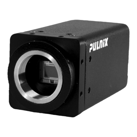
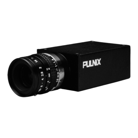
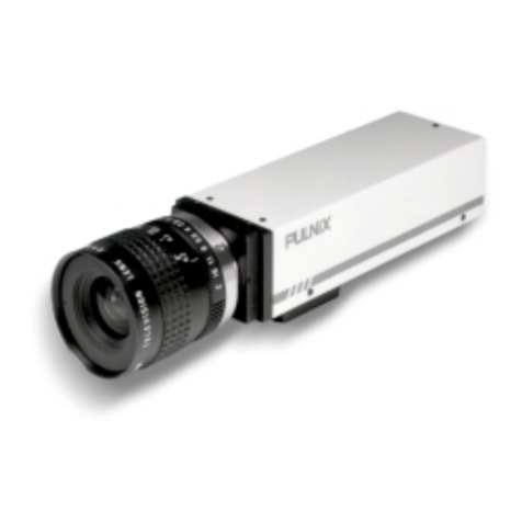
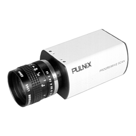
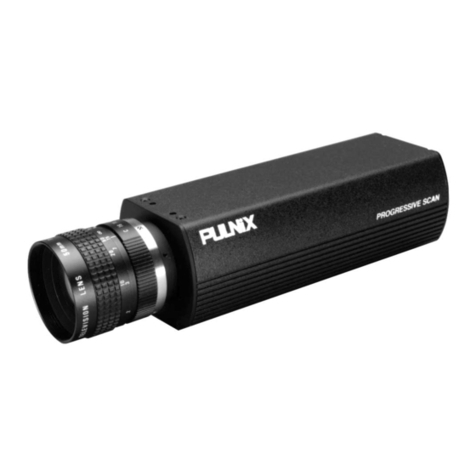
Pulnix TM-745E Manual

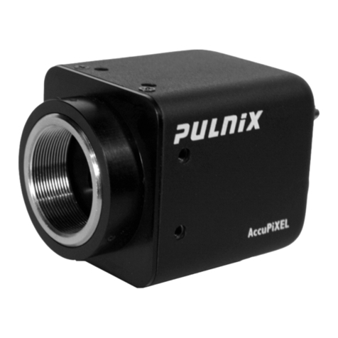
TM-745E/TM-765E
HIGH
RESOLUTION
CCD
CAMERA
OPERATIONS
&
MAINTENANCE
MANUAL
69-0032
Rev.
1

10.
TABLE
OF
CONTENTS
Pages
Features
and
Applications
шишинннннненнннннненнннннненененннннння
2
Specifications
пинин
3
Physical
Dimensions
Полин
4
Camera
System
Accessories.
.....................а
а-а-а
ыы
5
4.1
Shutter
Control
Unit-
Auskenner
iger
5
4.2
Power
babe.
nee
5
4.3
E,
7.
MR
5
4.4
Power
Supplies
.........ло.ы-ы
ыы
а-а
5
Setup
and
Operation
—
04.....................2Д....2...
ЛД.
4
4.
5
5.1
Lens
Мооп/
2.2...
ааа
арамы
ааа
5
5.2
Auto-lris
LENSES
ЛУО
О
О
ы
ент
Sewes
SVs
6
53
Shutter
Control
Unit
(SC-745)
Шуи
нее
неееенненене
ененнен
нн
6
5.4
Power
Cables
and
Power
Supplies
оше
6
5.5
EO
UT
RM
алымы
ыры
6
5.6
External
Sync
олшишиииинненнненненченененененненннененнненененнненененее
6
5.7
Interlace/Non-InterlaCe
Полина
7
TM-745E/TM-765E
Shutter
Camera
Application
—
sess
eee
n
7
6.1
BCD
Shutter
Control
“:
cuneis
pacati
aea
erus
cte
ORA
Ense
7
6.2
Substrate
Drain
Shutter
Mechanism
/.....................
nennen
enne
8
6.3
High
Speed
Shutter
Option
оопииишиииииннненненненненененнченненннненнненнне
9
6.4
Integration
——————À
9
6.5
Integration
Control
РИв2..............мала
ааа
10
Camera
Versions
and
Options
—
...........................22.22
tnter
nnne
nennen
10
CCD
Characteristics
and
Operation
|
sse
eene
netten
10
8.1
Theory
of
Орегайцип//2.......о..л
ааа
--.-.---
шә...
10
8.2
Mechanism
of
CCD
Charge
Transfer
............................2.2..........
11
8.3
Spectral
Response
Полин
11
Timing
Charts
and
Special
Functions
Полин
12
9.1
Output
Signal
Timing
Спайя/............2.2.2.2...244.24.4.424.49049З.9ә8
М...
12
9.2
Special
Functions
A
"—————À
Ann
nt
tata
13
Factory
Setting
and
Board
Layouts
—
——
sss
nenne
enne
nnne
14
10.1
Driver
Board(Top
Side)
пишиииииниеннннннннненннчнннинечененнеченннне
14
10.2
Driverd
Board(Bottome
Side)
Ппопииинененнннннененнннннннннненнння
14
10.3
Signal
Board
—
sse
tenente
entente
tenen
eene
ten
nennen
tenen
entente
nnn
14
en
=
ż
`
22
А
дами
желе
an
a
b
nn
een
жане
a
аана
SECTION
1
FEATURES
AND
APPLICATIONS
HIGH
RESOLUTION,
INTERLINE
TRANSFER
CCD
The
TM-745E/TM-765E
is
a
state-of-the-art
CCD
camera
which
uses
a
2/3
inch
high
resolution
imager.
This
unit
offers
outstanding
compactness,
high
performance,
long
Ше,
high
stability
as
well
as
a
number
of
technical
innovations
such
as
variable
electronic
shutter
and
random
ССО
integration.
Its
diversified
features
allow
for
versatile
applications
such
as
machine
vision
and
image
processing,
robotics,
medical,
and
surveillance
applications.
VARIABLE
ELECTRONIC
SHUTTER
AND
RANDOM
CCD
INTEGRATION
The
TM-745E/TM-765E
has
a
substrate
drain-type
shutter
mechanism
which
provides
a
superb
picture
at
various
speeds
without
smearing.
The
camera
has
the
capability
to
externally
vary
the
electronic
shutter
rate
via
a
manually
controlled
BCD
switch
from
1/60
to
1/10,000
sec.
in
discrete
steps
(1/31,000
sec.
optional).
Random
field
CCD
integration
is
available
.
Full
frame
integration
is
possible
through
special
modifications.
MINIATURIZED
AND
LIGHTWEIGHT
Ali
PULNiX
cameras
are
built
with
the
same
design
principles,
that
is:
solid
state
technology;
miniaturization
(including
lenses,
housings,
and
cables);
specialization
(such
as
remote
imager
and
image
intensified
camera
versions).
The
use
of
a
CCD
image
sensor
in
the
video
camera
module
and
the
development
of
special
mini
C-
mount
lenses
makes
it
possible
to
produce
a
very
compact,
lightweight,
and
robust
series
of
cameras.
LONG
LIFE:
A
THREE
YEAR
WARRANTY
The
CCD
solid
state
image
sensor
allows
the
camera
to
maintain
a
superior
performance
level
indefinitely
while
requiring
virtually
no
maintenance.
PULNIX
backs
all
of
the
TM
series
cameras
with
a
three
year
warranty.
WARNING:
Unscrewing
the
camera
cover
or
opening
the
camera
in
any
way
will
void
this
warranty.
PRECISE
IMAGE
GEOMETRY
On
the
CCD
image
sensor,
the
photosensor
elements
form
exact
rows
both
horizontally
and
vertically
so
that
a
very
precise
image
geometry
may
be
obtained.
Moreover,
the
TM-765E
image
sensor
features
uniform
square
pixels
(11
x
11
microns)
making
it
an
obvious
choice
for
use
with
computer
image
processing
systems
or
for
precise
pattern
measurements
and
gauging.
LOW
LAG
AND
HIGH
RESISTANCE
TO
IMAGE
BURNING
Compared
to
the
lag
of
conventional
cameras
which
use
a
pickup
tube,
the
lag
of
a
CCD
camera
is
considerably
reduced
so
that
a
clear
picture
may
be
obtained
when
shooting
a
rapid
moving
object,
or
when
shooting
in
a
low
illumination
environment.
Since
the
CCD
is
highly
resistant
to
image
burning,
the
camera
may
be
exposed
to
bright
objects
for
a
long
period
of
time.
It
must
be
noted
that
a
“smear”
phenomenon
may
occur
when
shooting
а
very
bright
object.
An
infrared
cutoff
filter
is
recommended
to
obtain
a
clear
picture.
HIGH
SENSITIVITY
The
TM-745E/TM-765E
is
one
of
the
most
low
light
sensitive
CCD
cameras
available
today.
This
is
especially
important
when
using
the
faster
shutter
speeds.
The
CCD
detects
images
into
the
near
infrared.
It
requires
only
0.5
lux
of
minimum
illumination
and
0.2
lux
minimum
illumination
at
maximum
gain.
In
general,
such
a
low
light
camera
allows
use
of
a
higher
lens
F-value
and
provides
greater
depth
of
field
and
sharper
images.
HIGH
RESISTANCE
TO
MAGNETIC
FIELD
AND
VIBRATION/MECHANICAL
SHOCK
Due
to
its
ruggedized
design,
the
CCD
imager
can
withstand
strong
vibration
and
shock,
and
little
or
no
noise
will
appear
in
the
picture.
Since
the
TM-745E/TM-765E
camera
is
not
influenced
by
a
magnetic
field,
it
will
produce
stable
images
even
when
placed
next
to
objects
such
as
electric
turnaces,
welding
machines,
or
NMR
scanners.
QUICK
START-UP
AND
LOW
POWER
CONSUMPTION
No
more
than
a
half
second
is
needed
for
the
TM-745E/TM-765E
to
warm
up,
and
shooting
may
begin
within
a
second
after
turning
on
the
camera.
The
power
consumption
is
only
4.0W.
This
makes
the
cameras
excellent
for
use
with
battery
operated
systems.

GENLOCK
CIRCUIT
А
genlock
circuit
is
built
into
the
TM-745E/TM-765E
to
accept
external
sync
for
industrial
applications
as
well
as
for
surveillance
locking.
This
flexible
genlock
will
take
either
interlace
or
non-interlace
H
and
V
sync.
AGC
SELECTION,
MANUAL
GAIN
CONTROL
AND
GAMMA
ADJUSTMENT
The
AGC
(automatic
gain
control)
may
be
switched
internally
from
automatic
to
fixed
gain.
Gamma
may
be
set
either
to
1
or
to
maximum
compensation
0.45.
These
adjustments
are
particularly
important
in
vision
system
applications.
External
sync:
TV
resolution:
Video
output:
SIN
ratio:
Minimum
illumination:
AGC:
Gamma:
Lens
mount:
Power
requirement:
Operating
temperature:
Storage
temperature:
Operating
humiditv:
Storage
humiditv:
Vibration:
Shock:
Camera
bodv:
Remote
imager:
Remote
imager
cable:
SECTION
2
SPECIFICATIONS
Imager:
2/3
inch
interline
transfer
CCD
Pixels
768
(H)
x
493
(V)
-
TM-745E
756
(H)
x
581
(V)
-
TM-765E
Cell
size 11.0
(H)
x
13.0
(V)
microns
-
TM-745E
11.0
(H)
x
11.0
(V)
microns
-
TM-765E
Sensing
area
8.8
(H)
x
6.6
(V)
mm
Dynamic
range
67dB
Low
noise,
blooming
suppression
Chip
size
10.0
mm
(H)
x
9.3
mm
(V)
Scanning:
525
lines,
2:1
interlace
-
TM-745E
(EIA)
625
lines,
2:1
interlace
-
TM-765E
(CCIR)
Clock
28.6363
MHz
-
TM-745E
28.375
MHz
-
TM-765E
Pixel
clock
14.31818
MHz
-
TM-745E
14.1875
MHz
-
TM-765E
Horizontal
frequency
15.734
KHz
-
TM-745E
15.625
KHz
-
TM-765E
Vertical
frequency
59.94
Hz
-
TM-745E
50.0Hz
-
TM-765E
Sync:
Internal/external
auto
switch
Ho/Vo,
4.0V
p-p,
4.7KQ
impedance
Frequency
tolerance
-
within
%5%
Interlace/non-interlace
Jitter
within
20
nsec.
Locking
time
within
2
sec.
(when
power
is
on)
570(H)
x
485(V)
lines
-
TM-745E
560(H)
x
575(V)
lines
-
TM-765E
1.0V
p-p
composite
video,
750
50
dB
min.
0.5
lux
(F=1.4)
without
IR
cut
filter
On
(12dB
standard,
17dB
max)
/
Off
0.45
or
1
C-mount
DC
12V
+
10%,
250mA
-10
°C
to
+50
°C
-30
°C
to
+60
°C
Within
70%
Within
90%
7G
(200Hz
to
2000Hz)
70G
-
51mm
x
44mm
x
159mm
(L)
190
grams,
2.0"
x
1.73"
x
6.3"
42mm
x
32mm
x
36.6mm
(|)
20
grams,
1.65"
x
1.26"
x
1.44"
48
inches
standard;
up
to
84
inches
optional

SECTION
3
PHYSICAL
DIMENSIONS
-
[oo
118
mm
(Remote)
|
—
~
SQUARE
25
PATTERN
1/4-20
UNC
-2В
REAR
PANEL

ЗЕСТЮН
4
CAMERA
SYSTEM
ACCESSORIES
The
TM-745E/TM-765E
consists
of
the
camera
body
and
the
lens
mount.
Additionally,
PULNIX
offers
the
following
accessories:
4.1
SHUTTER
CONTROL
UNIT
(SC-745)
consists
of
a
manually
controlled
8-position
BCD
switch
that
determines
the
exposure
time
of
the
sensor.
It
connects
to
the
TM-745E/TM-765E
via
a
cable
with
a
PC-6P
male
connector
that
plugs
into
the
6-pin
female
connector
socket
on
the
back
of
the
camera.
The
SC-745
for
shutter
control
is
included
with
camera.
4.2
POWER
CABLES
-
all
power
cables
use
a
PC-12P
female
connector
that
fits
into
the
12-pin
male
connector
on
the
back
of
the
camera.
Due
to
the
connector's
miniature
size,
PULNiX
recommends
purchasing
the
following
pre-assembled
cables:
KC-10
10
feet,
4
conductor
cable
(12V,
GND,
Hd,
Vd);
12POX
variable
length,
8
conductor
cable
(12V,
GND,
Но,
Мо,
video,
Async
reset,
integration
control)
Note:
Consult
PULNIX
for
custom
cable
assemblies.
4.3
LENSES
-
PULNIX
offers
a
wide
variety
of
2/3
inch
format
mini
lenses.
Auto-iris
lenses
must
have
a
cable
equipped
with
a
PC-6P
connector
mating
into
the
6-pin
female
connector
on
the
back
of
the
camera.
Note:
Normally,
the
TM-745E/TM-765E
cannot
do
variable
shuttering
while
using
an
auto-iris
lens
because
these
functions
share
one
6-pin
socket.
The
user
has
to
build
his
own
interface
in
order
to
use
both
an
auto-iris
lens
and
a
shutter
control switch.
This
is
done
by
separating
the
+12VDC,
GND
and
video
wires
(for
the
auto-iris
lens),
and
the
Do,
D1,
and
D2
controls
(for
the
BCD
switch).
4.4
POWER
SUPPLIES
-
PULNiX
recommends
the
following supplies:
K25-12
110V
AC/12V
DC,
2.1A
regulated
supply
P-15-12
220V
AC/12V
DC,
2.1A
regulated
supply
K50-12
110V
AC/12V
DC,
4.2A
regulated
supply
PD-12P
110V
AC/12V
DC,
0.5A
regulated
supply
SECTION
5
SETUP
AND
OPERATION
The
operation
of
the
TM-745E/TM-765E
requires
a
lens
(mini
or
standard
C-mount),
a
12V
DC
regulated
power
supply,
power
and
video
cable
assemblies
and,
if
needed,
a
shutter
control
unit.
Setup
of
the
camera
system
is
as
follows:
5.1
LENS
MOUNT
The
TM-745E
and
TM-765E
cameras
have
a
permanent
C-mount
attached
to
the
imager
portion
of
the
camera.
Lenses
are
mounted
by
carefully
threading
the
lens
into
the
mount
in
a
clockwise
direction.
Turn
the
fens
until
completely
seated
on
the
mount.
Most
all
standard
C-mount
lenses
should
fit
the
TM-745E/TM-765E.
However,
some
specialized
lenses
may
have
an
extremely
long
flange
back
which
exceeds
the
mounting
depth
of
the
camera.
Do
not
force
a
lens
which
does
not
appear
to
fully
seat.
Lens
extention
tubes
such
as
the
CR-5,
CR-10,
and
CR-20
are
used
by
attaching
first
to
the
lens
and
then
mounting
the
entire
assembly
to
the
camera.
CS
style
lenses,
though
they
share
the
common
C-mount
thread,
are
not
compatible
with
the
standard
TM-745E/TM-765E
mount
due
to
a
different
rear
focus
specification
for
the
CS
format.

5.2
AUTO-IRIS
LENSES
Auto-iris
lenses
require
a
6-pin
male
connector
(РС-6Р)
mating
into
the
female
connector
on
the
back
of
the
camera.
Connect
+12V
DC,
GND
and
Video
to
each
pin
as
indicated
in
the
following.
N
Connector
©
©
6-PI
о
9
ab.
M
А
.
ро
(2
©)
3.
Video
6.
D1
5.3
SHUTTER
CONTROL
UNIT
(SC-745)
The
TM-745E/TM-765E
uses
a
manually
controlled
8-position
BCD
switch,
SC-745,
to
set
the
shutter
speed
of
operation.
The
switch
is
connected
to
the
camera
via
a
cable
that
has
a
PC-6P
male
connector
attached
to
it
which
plugs
into
the
above
illustrated
6-pin
camera
socket.
5.4
POWER
CABLES
AND
POWER
SUPPLIES
The
TM-745E/TM-765E
uses
a
PC-12P
mating
12-pin
power
connector.
If
using
any
of
the
PULNIX
connector
and
cable
assemblies,
please
note
that
the
yellow
lead
is
+12V
DC
and
gray
is
GND.
Connect
the
yellow
lead
to
the
+12V
of
the
power
supply
and
attach
the
gray
lead
to
the
power
supply’s
ground.
Make
sure
all
other
leads
are
not
touching
as
this
will
cause
the
camera
to
malfunction.
When
powering
the
camera,
use
only
a
regulated
12VDC
power
supply.
The
TM-745E/TM-765E
has
a
narrow
voltage
intake
range
(11V
to
14V
max).
If
unregulated
voltage
or
voltage
lower
than
11V
is
applied,
noise
will
appear
on
the
monitor.
12-PIN
Connector
1.
GND
7.
Vp
In
2.
+12V
DC
8.
GND
3.
GND
9.
Hp
In
4.
Video
Out
10.
МС
5.
СМО
11.
Integration
Control
6.
Vinit
12.
GND
6-PIN
Connector
1.
D2
4.
+12V
DC
2.
GND
5.
DO
3.
Video
6.
D1
NOTE:
Do,
Di,
D2
are
shutter
control
inputs.
5.5
VIDEO
OUTPUT
The
video
output
impedance
of
the
camera
is
7502
and
requires
a
coaxial
cable
with
matching
impedance.
The
end
of
the
video
cable
or
the
monitor
must
be
terminated
а!
750
as
well.
Standard
video
cable
with
proper
video
connectors
may
be
obtained
at
most
electronics
hardware
stores.
Connect
one
end
of
the
video
cable
into
the
standard
video
connector
located
on
the
back
of
the
camera
and
insert
the
other
end
of
the
cable
into
the
CCTV
monitor.
Alternatively,
video
output
is
also
transmitted
via
pin
4
of
the
camera’s
12
pin
connector.
5.6
EXTERNAL
SYNC
The
TM-745E/TM-765E
does
not
require
external
sync
in
order
to
run
directly
into
a
CCTV
monitor.
However,
some
applications
(such
as
multiple
camera
switching
and
some
vision
systems)
will
require
that
the
camera
be
externally
synced.
The
unit
has
a
built-in
genlock
circuit
which
will
accept
an
external
Hp
and
Ур
sync
signal;
the
built-in
phase
lock
loop
(PLL)
adjusts
its
internal
frequency
to
lock
the
camera
to
the
external
sync
by
allowing
the
internal
crystal
oscillator
to
automatically
switch
to
a
voltage
controlled
oscillator.
Pins
7
and
9
of
the
TM-
745E/TM-765E's
12-pin
connector
accept
external
Ур
and
Hp.
6

созады
ШЫ
A
aa
НЫ
аа
wma
rd
en
—
i
с.
5.7.
INTERLACE/NON-INTERLACE
:
Interlace
sync
is
a
standard
TV
sync
where
the
vertical
sync
alternates
the
ода
and
even
fields
of
a
frame
of
video.
Non-interlace
sync
scans
one
field
only.
The
pulse
relationship
is
shown
below.
261
262
263
264
524
525
1
2 3
1
2
3
Hp
|
|
|
|
|
|
|
|
l
|
|
|
!
t
1
1
ур
EE
XN
„е...
interlace
261
262
1
2
261
262
1
2
261
262
1
2
Но
|
|
|
|
|
|
|
|
|
|
!
1
i
1
1
U
Ур
"M
|
Non-interlace
|
|
The
internal
genlock
of
the
camera
operates
in
the
interlace
mode.
When
external
sync
is
applied,
operation
can
be
performed
in
either
interlace
or
non-interlace
mode
by
changing
the
input
condition
of
the
Vp
signal
as
shown
above.
SECTION
6
TM-745E/TM-765E
SHUTTER
CAMERA
APPLICATION
6.1
BCD
SHUTTER
CONTROL
By
selecting
DO,
D1,
D2
level
high
or
low,
the
following
shutter
speed
is
obtained,
PULNIX
provides
a
shutter
control
(SC-745),
but
it
is
easily
controlled
from
the
computer,
remote
control
unit,
or
fixed
at
a
certain
speed.
OO
6-PIN
Connector
1.
D2
4.
+12V
©
©
2.
GND
5.
Do
O
С)
3.
Video
6.
01
Shutter
control
SC-745
Controller
Setting
1
2
3
4
5 6
7
sec
1/125
1/250
1/500
1/1000
1/2000
1/4000
1/10,000
Do
H
L
H
L
H
L
H
D:
L-
H
H
L
L
H
H
D2
L
H

l-l
n
Surface
COD
surface
Potential
well
Vsub
=
normal
mode
Si
substrate
Charge
drain
to
‘
a
substrate
Normal
operation
requires
the
CCD
chip
to
construct
an
individual
potential
well
at
each
image
cell.
These
potential
wells
are
separated
from
each
other
by
a
barrier.
The
barrier
is
sequentially
removed
to
transfer
the
charge
from
one
ССО
to
another
by
the
pixel
clock.
This
is
the
basic
principle
of
CCD
operation
for
interline
transfer.
The
substrate
drain
verticallv
moves
the
charges.
When
excess
potential
is
applied
to
substrate
underneath
each
cell,
a
potential
barrier
is
pulled
down
to
release
the
charge
into
the
drain.
This
can
happen
to
all
the
cells
simultaneousiv,
whereas
normal
CCD
shuttering
is
done
with
a
horizontal
charge
shift
to
the
drain
area
by
interline
transferring
or
reverse
transferring
of
the
frame
transfer
chip.
|
ж”
Shutter
exposure
time
OA
Transfer
gate
Hp
\
Shutter
control
dal
Discharge
to
Vsub
pulse
M
substrate
Но
|
|
|
|
|
|
Vsub
pulse
fe
ap
кен
Қ
(ен
Бар
The
discharge
of
TM-745E/TM-765E
is
done
in
the
horizontal
blanking
interval.
Note:
Vertical
resolution
of
shutter
mode
is
one
field
(244).
Full
frame
shutter
is
not
available.
If
the
object
is
still,
the
interlace
signal
(2
fields)
can
generate
full
vertical
resolution.
e
A
i
t
a
aa
re

6.3
HIGH
SPEED
SHUTTER
OPTION
With
optional
modification
(option
#29-4),
The
TM-745E/TM-765E
is
capable
of
increasing
the
shutter
speed
up
to
1/31,500
sec.
The
BCD
control
for
high
speed
option
is:
е
а
=
=
e
6
d
Іт
гэ
Standard
High
Speed
(option
#29-4)
1/60
1/60
1/125
1/126
1/250 1/254
1/500
1/508
1/1000 1/1050
1/2000
1/2250
1/4000
1/5250
1/10,000 1/31,500
L
H
L
H
L
H
L
H
NOOR
WNH
~*~
о
ттггттгг rrrrrrrr
6.4
INTEGRATION
The
TM-745E/TM-765E
can
operate
with
long
exposures
(Integration
mode).
Due
to
the
interline
transfer,
full
frame
resolution
is
obtained.
(Note:
Full
frame
is
not
available
in
the
shutter
mode).
1.
Select
frame
mode
on
driver
PCB
(Factory
standard).
If
the
setting
is
in
the
field
mode
in
order
to
enhance
shutter
sensitivity,
move
solder
jumper
to
frame
side.
2.
Apply
the
integration
control
to
low
(GND)
to
pin
#11
of
12-pin
connector.
This
allows
the
TM-745E/TM-765E
to
operate
with
integration.
3.
Арру
ext.
sync
(Hp, Мо);
Hp
-
continuous,
Мр
-
continuous
or
integration
control
interval
pulse.
6.5
INTEGRATION
CONTROL
PULSE
уа
A
xsgil
e
PI
XSG2
| |
A
|
|
INTEGRATION
CONTROL
BE
\
A
VIDEO
QUTPUT
А
/
\
/ \
—
NOTE:
1.
XSG1
and
XSG2
are
transfer
gate
pulses.
They
аге
approximately
at
7.5H
(11.5H
for
TM-765)
after
Vd
falling
edge.
2.
No
transfer
gate
pulse
when
INTEGRATION
CONTROL
is
LOW.
3.
Two
fields
of
integrated
image
is
available
after
INTEGRATION
CONTROL
changed
to
HIGH.

ЗЕСТОН
7
CAMERA
VERSIONS
AND
OPTIONS
1.
Automatic
gain
control
(AGC)
disabled
-
gain
set
to
fixed
value.
2.
Blemish
free
imager
-
no
bad
pixels
or
compensating
PROMS.
3.
Internal
infrared
(IR)
filter.
All
remote
imager
versions
are
already
equipped
with
it.
4.
Gamma
adjusted
to
0.45
-
standard
gamma
is
set
to
1.
10.
Remote
imager
cable
enters
at
the
rear.
11.
Remote
imager
cable
enters
at
the
right.
12.
Remote
imager
cable
enters
at
the
left.
13.
Remote
imager
enters
at
the
top.
14.
Remote
imager
enters
at
the
bottom.
15.
Detachable
remote
imager
at
the
camera
bodv.
23.
Pixel
clock
out.
25.
Pinout
compatible
with
Sony
XC-38/39.
29.
Set
shutter
at
1/30,000
sec.
SECTION
8
CCD
CHARACTERISTICS
AND
OPERATION
8.1
THEORY
OF
OPERATION
(Operation
principle
of
the
CCD)
А
CCD
(Charge
Coupled
Device)
consists
of
MOS
(Metal-
Oxide-Semiconductor)
capacitors
arranged
in
a
regular
array.
и
basically
performs
three
functions
connected
with
handling
charges.
1.
Photoelectric
conversion
(photosensor)
\
ж
жа
LLLA
Incident
light
generates
charges
on
the
MOS
capacitors,
with
zz
waa
wu
|2
the
quantitv
of
charge
being
proportional
to
the
brightness.
222222222
МА
72222227222
2222
2.
Accumulation
of
charges
A
uum
us
EZ
When
a
voltage
is
applied
to
the
electrodes
of
the
MOS
capacitors,
an
electric
potential
well
is
formed
in
the
silicon
22204
VALUMDMELA
ет
427277722
layer.
The
charge
is
accumulated
in
this
well.
d
uz
uum
umm
-—
transfer
direction
зА
pe
4-4
1
i
ip
t
1
U '
1 U
U
U
U
1
LI
+
U 1
1 '
t 1
1
1 1
i
1
1
е
в
3.
Transmission
of
charge
When
a
high
voltage
is
applied
to
the
electrodes,
a
deeper
well
is
formed;
when
a
low
voltage
is
applied,
a
shallower
well
is
formed.
Inthe
CCD,
this
property
is
used
to
transmit
the
charge.
When
a
high
voltage
is
applied
to
the
electrodes,
a
deep
electric
potential
well
is
formed,
and
charge
flows
in
from
neighboring
well.
When
this
is
repeated
over
and
over
among
the
regularly
arranged
electrodes,
the
charge
is
transferred
from
one
MOS
capacitor
to
another.
This
is
the
principle
of
CCD
charge
transmission.
чке
ке
a
an
5
5
-
S
10

8.2
MECHANISM
OF
ССО
CHARGE
TRANSFER
1.
Vertical
transfer
2
The
vertical
shift
register
transfers
charges
using
а
four-phase
=
drive
mode.
Figure
1
shows
an
example
of
the
changes
which
can
occur
in
potential
wells
in
successive
time
intervals.
At
tO,
the
electrode
voltages
are
(V1
=
V2)>(V3
=
V4),
so
the
potential
wells
are
deeper
toward
the
electrode
at
the
higher
voltages
V1
and
V2.
Charges
accumulate
in
these
deep
wells.
Atti,
the
electrode
voltages
are
(V1
=
V2
=
V3)>(V4),
so
the
charges
accumulate
in
the
wells
toward
the
electrode
at
V1,
V2
and
V3.
At
12,
the
electrode
voltages
are
(V2
=
V3)>(V4
=
V1),
so
the
charges
accumulate
in
the
wells
toward
|
the
electrode
at
V2
and
МЗ.
Electrode
voltage
states
at
t3
and
potential
profile
—
os
*
-
(mi
sh
lowe:
after
are
shown
below.
a
ошту
concentration
potential
profile
t3(V2
=
УЗ
=
V4)>(V1)
t4(V3
z
V4)>(V1
2
V2)
Operating
Pulse
Waveforms
(a1,
92
of
@H1,
на)
t5(V4>(V1
=
V2
=
V3)
t6(V4
=
V1)>(V2
=
V3)
t7(V4
=
М1
=
V2)>(V3)
t8(V1
=
V2)>(V3
=
V4)
(Initial
state)
These
operations
are
repeated
to
execute
the
vertical
transfer.
The
interline-transfer
mechanism
of
the
CCD
2.
Horizontal
transfer
The
horizontal
shift
register
transfers
charges
using
a
two-
phase
drive
mode.
Figure
2
shows
an
example
of
the
changes
which
can
occur
in
the
potential
wells
in
successive
time
intervals.
Atti,
the
electrode
voltages
are
H1>H2,
so
the
potential
wells
are
deeper
toward
the
electrode
of
the
higher
voltage
H1.
The
charges
accumulate
in
these
wells.
At
t2,
Output
section
the
electrode
voltages
H1
and
H2
are
inverted,
the
wells
eae
(818
element)
————4
toward
the
electrode
at
voltage
H2
becomes
deeper
while
the
|
Horizontal
wells
toward
the
electrode
at
voltage
Н1
become
shallower.
ине
So
the
wells
at
H2
are
deeper
than
those
at
H1,
the
charge
odd
line
flows
into
the
deeper
wells
toward
the
electrode
at
H2.
At
t3,
even
ine
the
electrode
voltage
has
not
changed
since
t2,
so
the
charge
flows
into
the
wells
at
H2
and
one
transfer
of
charge
is
completed.
These
operations
are
repeated
to
execute
the
horizontal
transfer.
odd
line
Е
с
A
Е
2
©
e
B
28
Vertical
shift
register
8.3
SPECTRAL
RESPONSE
Two
phase
CCD
charge
transfer
Wave
Length
(nm)
11

SECTION
9
TIMING
CHARTS
and
SPECIAL
FUNCTIONS
9.1
OUTPUT
SIGNAL
TIMING
CHARTS
e
4
e
БЕРРЕЕРДЕРЕН
EEE
E
ПИР
Timing
chart
vertical
ттт
„пат
12

9.2
SPECIAL
FUNCTIONS:
9.2.1
SHUTTER
The
TM-745E/765E
has
a
built
in
shutter
control
up
to
1/10,000
sec.
As
an
option,
1/31,500
sec.
shutter
speed
is
available.
When
this
option
is
selected,
Vp
phase
adjustment
option
is
not
available.
VD
phase
adjustment
is
used
to
align
video
vertical
timing
to
external
sync
leading
edge.
Standard
without
adjustment
is
3.5H
(fixed).
Phase
adjusted
au
Ext.
Vd
The
shutter
timing
is
synchronized
with
the
CCD
transfer
gate
timing
of
each
field.
Because
of
the
shutter
principle,
=
oniv
опе
field
image
per
shutter
is
output.
If
one
frame
of
Int.
Vd
à
| |
shutter
image
is
captured,
two
separate
images
will
be
displayed
due
to
object
motion.
9.2.2
INTEGRATION
Integration
is
a
longer
exposure
than
the
standard
1/30
sec.
of
frame
speed.
The
TM-745E/765E
provides
a
full
frame
of
integration
image.
Pin
11
of
the
12-
ki
pin
connector
is
used
to
control
integration.
The
standard
model
is
normally
pulled
up
(5V),
and
when
Pin
11
is
Low
(GND),
the
TM-745E/765E
maintains
the
integration
until
Pin
11
goes
to
high.
‘SHUTTER
INTEGRATION
The
integration
image
is
quite
different
from
TM-840N(frame
transfer
CCD).
TM-745E/765E
signal
processing
keeps
optical
black
level
as
reference
black
video
to
clamp
the
video
level,
and
thermal
noise
during
integration
is
cancelled
off.
Non-optical
black
clamping
is
also
available
as
an
option.
Please
consult
PULNIX
for
special
integration
applications.
13

SECTION
10
FACTORY
SETTING
AND
BOARD
LAYOUTS
10.1
DRIVER
BOARD
(TOP
SIDE)
Jumper
Setting:
wi
OPEN
W2
OPEN
МЗ
FLD/FRM
FRM(Short)
W4
OPEN
W7
OPEN
Voltag
e
5
etting:
TM-745E
DRIVER
BOARD
REV.E
(TOP
SIDE)
VR1
Vsub
Optimize
it
by
checking
the
picture,
make
sure
there
is
no
grainy
picture.
VR3
VD
Phase
Apply
ext.
VD
to
the
camera,
and
probe
int.
HD.
Adjust
VR2
so
that
both
ext.
vD
and
Int.
VD
will
be
lined
up.
10.2
DRIVER
BOARD(BOTTOM
SIDE)
Voltage
Setting:
VR2
PLL
Apply
ext.
HD
to
the
camera,
and
probe
int.
HD.
Adjust
VR1
so
that
both
ext.
HD
and
int.
HD
phase
will
be
lined
up.
The
delay
should
be
less
II
than
20
nsec.
TM-745E
DRIVER
BOARD
REV.
Е
(BOTTOM
SIDE)
10.3
SIGNAL
BOARD
A
WC
ЕБ
Jumper
Setting:
VRI
vr2
VR3 VR4
W1
АВС
ON/OFF
АСС
OFF(RIGHT)
м
А
W4
GAMMA
1/0.45
1.0
(RIGHT)
силна
b
W5
ENH
ON(3)/OFF(1)
ON
(RIGHT)
ua
nn
b
GAMMA
4
‘ome?
-
Voltage
Setting:
VR1
AGC
1.940.1V
VR2
MGC
3.2+0.1V
VR3
AGC
MAX
2.0+0.1V
VR4
PED
50+0.1mV
VR5
ENH
OV
VR6
W/C
OV
14

NOTICE
The
material
contained
in
this
manual
consists
of
information
that
is
proprietary
to
PULNiX
America,
Inc.,
and
may
only
be
used
by
the
purchasers
of
this
product.
PULNiX
America,
Inc.
makes
no
warranty
for
the
use
of
its
products
and
assumes
no
responsibility
for
any
errors
which
may
appear
or
for
damages
resulting
from
the
use
of
the
information
contained
herein.
PULNiX
America,
Inc.
reserves
the
right
to
make
changes
without
notice.
WARRANTY
All
our
solid
state
cameras
have
a
full
three
year
warranty.
If
any
such
product
proves
defective
during
this
warranty
period,
Pulnix
America,
Inc.
will
repair
the
defective
product
without
charge
for
parts
and
labor
or
will
provide
a
replacement
in
exchange
for
the
defective
product.
This
warranty
shall
not
apply
to
any
damage,
defect
or
failure
caused
by
improper
use
or
inadequate
maintenance
and
use.
Revised
Printing:
December,
1995
In
Australia
In
the
U.K.
In
Germany
іп
Japan
PULNIX
America
Inc.
PULNIX
Europe
Lid.
PULNIX
Europe
Ltd.
Takenaka
System
Ca.
Lid.
„
Unit
16,
#35
Garden
Road
Aviary
Court,
Wade
Road
Steinbruch
5
7-1,
Shinomiya
Narano
Cho
Hayton,
Vic
3168
Basingstoke,
Hants
RG24
8PE
D-8755
Alzenau
Yamashina-ku,
Kyoto,
607
fel:
3-9546-0222
Tel:
01256-475555
PULNIX
еш
Products
Division
Tel:
06023-4666
Tel:
075-593-9787
Fax:
3-9562-4892
Fax:
01256-466268
merica
Inc.
Tel:
408-747-0300
1330
Orleans
Drive
Sunnyvale,
CA
94089
Tel:
800-445-5444
Fax:
408-747-0660
Fax:
06023-4667
Other manuals for TM-745E
1
This manual suits for next models
1
Table of contents
Other Pulnix Security Camera manuals

Pulnix
Pulnix TM-7200 User manual

Pulnix
Pulnix TMC-4200CL User manual

Pulnix
Pulnix TMC-7 User manual

Pulnix
Pulnix TM-1300 User manual

Pulnix
Pulnix TM-7 User manual

Pulnix
Pulnix TM-75 User manual

Pulnix
Pulnix TM-250 User manual

Pulnix
Pulnix TS-9720EN Series User manual

Pulnix
Pulnix TM-7CN User manual

Pulnix
Pulnix TM-5LC User manual