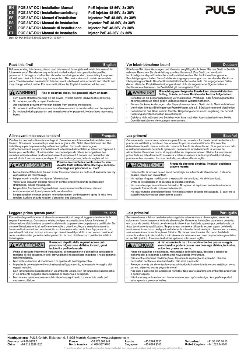
Puls POE.8AT-DC1 User manual

POE.8AT-DC1
48V, 8X 30W
May 2019 / Rev. 0.1 DS-POE.8AT-DC1-EN
All values are typical figures specified at 56Vdc supply voltage, 8x 30W output load, 25°C ambient temperature and after a 5 minutes
run-in time unless otherwise noted.
www.pulspower.com Phone +49 89 9278 0 Germany
1/10
Preliminary
P
O
E
INJECTOR
•DC 48-56V Input
•Efficiency 96.1%
•Width only 39mm
•8x 30W ports (acc.to IEEE 802.3 at)
•Data transfer rate 1000Mbps
•Temperature range -45°C and +85°C
•Plug & Play installation and DIN rail mounting
•3 Year Warranty
G
ENERAL
D
ESCRIPTION
The POE.8AT-DC1 is a DIN-rail mountable Power over
Ethernet (PoE) injector, which provides power for PoE
applications. It injects power to 8 individual PoE
channels (IEEE 802.3AT) via RJ45 Ethernet ports. The
device can supply powered devices PD of type 1 and
type 2.
S
HORT
-
FORM
D
ATA
DC input voltage
DC 48V
Nominal
DC input
voltage
range
48 – 56Vdc
For PD type 2 (30W /
channel) ,
the input
voltage must be above
51Vdc
Output
power 8x 30W
Below +60°C ambient
channels
8x 22.5W
At +85°C ambient
Derate linearly between +60°C and +85°C
Output current
limitation
0.63A
0.47A
Below +60°C ambient
At +85°C ambient
Efficiency
Losses
96.1%
4.2W
Temperature range
-45°C to +85°C
Size (w x h x d)
39x128x117mm
Without DIN-Rail
Weight
360g / 0.79lb
O
RDER
N
UMBERS
PoE Injector POE.8AT-DC1
Power Supply CP10.481
Mechanical Accessory ZM10.WALL
Wall/panel mount bracket
M
ARKINGS
IND. CONT. EQ.
UL 61010
planned
planned

POE.8AT-DC1
48V, 8X 30W
May 2019 / Rev. 0.1 DS-POE.8AT-DC1-EN
All values are typical figures specified at 56Vdc supply voltage, 8x 30W output load, 25°C ambient temperature and after a 5 minutes
run-in time unless otherwise noted.
www.pulspower.com Phone +49 89 9278 0 Germany
2/10
Preliminary
INDEX
Page Page
1. Intended Use .......................................................3
2. Installation Requirements...................................3
3. DC-Input...............................................................4
4. Output .................................................................4
5. Efficiency and Power Losses................................4
6. Functional Diagram.............................................4
7. Terminals and Wiring..........................................5
8. Front Side and User Elements.............................5
9. EMC......................................................................6
10. Environment........................................................6
11. Protection Features ............................................ 7
12. Safety Features ................................................... 7
13. Dielectric Strength.............................................. 7
14. Approvals............................................................ 8
15. Other Fulfilled Standards................................... 8
16. Physical Dimensions and Weight ....................... 9
17. Accessories ........................................................ 10
17.1. CP10.481....................................................10
17.2. ZM10.WALL – Wall/Panel Mount Bracket10
The information given in this document is correct to the best of our knowledge and experience at the time of
publication. If not expressly agreed otherwise, this information does not represent a warranty in the legal sense of the
word. As the state of our knowledge and experience is constantly changing, the information in this data sheet is
subject to revision. We therefore kindly ask you to always use the latest issue of this document (available under
www.pulspower.com).
No part of this document may be reproduced or utilized in any form without our prior permission in writing.
T
ERMINOLOGY AND
A
BREVIATIONS
PE and symbol PE is the abbreviation for Protective Earth and has the same meaning as the symbol .
Earth, Ground This document uses the term “earth” which is the same as the U.S. term “ground”.
T.b.d. To be defined, value or description will follow later.
AC 230V A figure displayed with the AC or DC before the value represents a nominal voltage with
standard tolerances (usually ±15%) included.
E.g.: DC 12V describes a 12V battery disregarding whether it is full (13.7V) or flat (10V)
230Vac A figure with the unit (Vac) at the end is a momentary figure without any additional
tolerances included.
50Hz vs. 60Hz As long as not otherwise stated, AC 100V and AC 230V parameters are valid at 50Hz mains
frequency. AC 120V parameters are valid for 60Hz mains frequency.
may A key word indicating flexibility of choice with no implied preference.
shall A key word indicating a mandatory requirement.
should A key word indicating flexibility of choice with a strongly preferred implementation.

POE.8AT-DC1
48V, 8X 30W
May 2019 / Rev. 0.1 DS-POE.8AT-DC1-EN
All values are typical figures specified at 56Vdc supply voltage, 8x 30W output load, 25°C ambient temperature and after a 5 minutes
run-in time unless otherwise noted.
www.pulspower.com Phone +49 89 9278 0 Germany
3/10
Preliminary
1. INTENDED USE
This device is designed for installation in an enclosure and is intended for commercial use, such as in industrial control,
process control, monitoring and measurement equipment or the like.
Do not use this device in equipment where malfunction may cause severe personal injury or threaten human life.
2. I
NSTALLATION
R
EQUIREMENTS
This device may only be installed and put into operation by qualified personnel.
This device does not contain serviceable parts.
If damage or malfunction should occur during installation or operation, immediately turn power off and send unit to
the factory for inspection.
This device is designed for convection cooling and does not require an external fan. Do not obstruct airflow and do
not cover ventilation grid (e.g. cable conduits) by more than 15%!
Keep the following installation clearances: 40mm on top, 20mm on the bottom, 5mm on the left and right sides are
recommended when the device is loaded permanently with more than 50% of the rated power. Increase this clearance
to 15mm in case the adjacent device is a heat source (e.g. another power supply).
A disconnecting means shall be provided for the output of the power supplies when used in applications according to
CSA C22.2 No 107.1-01.
WARNING
Risk of electrical shock, fire, personal injury or death.
- Do not use the injector without a proper grounded power supply (Protective Earth). It is recommended to ground
power supply –pole with PE.
- Turn power off before working on the device. Protect against inadvertent re-powering.
- Make sure that the wiring is correct by following all local and national codes.
- Do not modify or repair the unit.
- Do not open the unit.
- Use caution to prevent any foreign objects from entering the housing.
- Do not use in wet locations or in areas where moisture or condensation can be expected.
- Do not touch during power-on, and immediately after power-off. Hot surfaces may cause burns.

POE.8AT-DC1
48V, 8X 30W
May 2019 / Rev. 0.1 DS-POE.8AT-DC1-EN
All values are typical figures specified at 56Vdc supply voltage, 8x 30W output load, 25°C ambient temperature and after a 5 minutes
run-in time unless otherwise noted.
www.pulspower.com Phone +49 89 9278 0 Germany
4/10
Preliminary
3. DC-I
NPUT
Supply voltage
DC 48V Nominal
Supply voltage range
48 – 56Vdc For PD type 2 (30W / channel) , the input voltage
must be above 51Vdc
4. O
UTPUT
RJ45 Output
channels 8x 30W
8x 22.5W
Below +60°C ambient
At +85°C ambient
Derate linearly between +60°C and +85°C
Output current limitation
0.63A Below +60°C ambient
0.47A At +85°C ambient
5. E
FFICIENCY AND
P
OWER
L
OSSES
DC48V DC56V
Efficiency
Typ.
96.1%
95.6%
At 8x30W output
Power losses
Typ. 4.12W 4.21 At 8x30W output
6. F
UNCTIONAL
D
IAGRAM
Fig. 6-1 Functional diagram

POE.8AT-DC1
48V, 8X 30W
May 2019 / Rev. 0.1 DS-POE.8AT-DC1-EN
All values are typical figures specified at 56Vdc supply voltage, 8x 30W output load, 25°C ambient temperature and after a 5 minutes
run-in time unless otherwise noted.
www.pulspower.com Phone +49 89 9278 0 Germany
5/10
Preliminary
7. T
ERMINALS AND
W
IRING
The terminals are IP20 finger safe constructed and suitable for field- and factory wiring.
Input
Type
Hot swap connector
Max. wire size (litz wire)
1.5mm2
Max. wire size with ferrules
1.5mm
2
Wire size AWG
AWG 26-14
Maximum wire diameter
Max. 1.8mm
Wire st
ripping length 6mm / 0.25inch
Screwdriver
3.5mm slotted or cross-head No 2
Recommended tightening torque
0.8Nm, 7lb.in
Instructions:
a)
Use appropriate copper cables that are designed for minimum operating temperatures of:
60°C for ambient up to 45°C and
75°C for ambient up to 60°C minimum
90°C for ambient up to 70°C minimum.
b)
Follow national installation codes and installation regulations!
c)
Ensure that all strands of a stranded wire enter the terminal connection!
d
) Unused terminal compartments should be securely tightened.
e
) Ferrules are allowed.
8. F
RONT
S
IDE AND
U
SER
E
LEMENTS
Fig. 10-1
Front side
A Network output and power Ethernet PoE output
B DC power input Hot swap connector
C Network input Ethernet input
A
B
C

POE.8AT-DC1
48V, 8X 30W
May 2019 / Rev. 0.1 DS-POE.8AT-DC1-EN
All values are typical figures specified at 56Vdc supply voltage, 8x 30W output load, 25°C ambient temperature and after a 5 minutes
run-in time unless otherwise noted.
www.pulspower.com Phone +49 89 9278 0 Germany
6/10
Preliminary
9. EMC
The power supply is suitable for applications in industrial environment as well as in residential, commercial and light
industry environments.
EMC Immunity
According to generic standards: EN 61000-6-2 and EN 61000-6-4
Electrostatic discharge
EN 61000-4-2 Contact discharge
Air discharge
±4kV
±8kV
Criterion B
Criterion B
Electromagnetic RF field
EN 61000-4-3 80MHz-1GHz 3V/m Criterion A
Fast transients (Burst)
EN 61000-4-4 Input and Output lines 2kV Criterion B
Surge voltage on input
EN 61000-4-5 L PE ±0,5kV Criterion B
Surge voltage on output
EN 61000-4-5 + -
+ / - PE
±1kV
±4kV
Criterion C
Criterion C
Conducted disturbance
EN 61000-4-6 0.15-80MHz 3V Criterion A
EMC E
mission According to generic standards: EN 61000-6-3 and EN 61000-6-4
Conducted emission
input lines
EN 55011, EN 55015, EN 55022, EN 55032,
FCC Part 15, CISPR 11, CISPR 22
Class B
Conducted emission
output lines
1)
IEC/CISPR 16-1-2, IEC/CISPR 16-2-1
IEC/CISPR 22, EN 55032 (B)
Limits for DC power port according EN
61000-6-3 fulfilled
Radiated emission
EN 55011, EN 55022, EN 55032,
IEC/CISPR 16-2-3
Class B
This device complies with FCC Part 15 rules.
Operation is subjected to following two conditions:
(1) this device may not cause harmful interference, and (2) this
device must accept any interference received, including interference that may cause undesired operation.
1) For information only, not mandatory for EN 61000-6-3
10.
E
NVIRONMENT
Operational
temperature 1) -45°C to +85°C (-31°F to 185°F) Reduce output power according to Fig. 10-1
Storage temperature
-45°C to +85°C (-31°F to 185°F) For storage and transportation
Humidity
5 to 95% r.h. According to IEC 60068-2-30
Do not energize while condensation is present
Altitude
0 to 2000m (0 to 6 560ft) Without any restrictions
Over
-voltage category III According to IEC 62477-1 for altitudes up to
2000m
1) Operational temperature is the same as the ambient or surrounding temperature and is defined as the air temperature 2cm below the unit.
Fig. 10-1 Output power vs. ambient temp.
Allowed output power
Ambient temperature
0A
-45
8x 30W
0+60 +85°C
8x 22.5W

POE.8AT-DC1
48V, 8X 30W
May 2019 / Rev. 0.1 DS-POE.8AT-DC1-EN
All values are typical figures specified at 56Vdc supply voltage, 8x 30W output load, 25°C ambient temperature and after a 5 minutes
run-in time unless otherwise noted.
www.pulspower.com Phone +49 89 9278 0 Germany
7/10
Preliminary
11. P
ROTECTION
F
EATURES
Output protection
Electronically protected against overload, no-load and short-circuits.
Degree of protection
IP 20 EN/IEC 60529
Penetration protection
> 4mm E.g. screws, small parts
Over
-temperature protection Yes Output shut-down with automatic restart.
There is no correlation between the operating
temperature and turn-off temperature since this is
dependent on input voltage, load and installation
methods.
Input
polarity protection Diode
12. S
AFETY
F
EATURES
Input / output separation
Data channels galvanically isolated
13. D
IELECTRIC
S
TRENGTH
The output voltage is floating and has no ohmic connection to the ground. Type and factory tests are conducted by
the manufacturer. Field tests may be conducted in the field using the appropriate test equipment which applies the
voltage with a slow ramp (2s up and 2s down). Connect all input-terminals together as well as all output poles before
conducting the test. When testing, set the cut-off current settings to the value in the table below.
Fig. 13-1 Dielectric strength A B C
Type test 60s 500Vac 500Vac 1500Vac
Factory test 5s 500Vac 500Vac 1500Vac
Field test 5s 500Vac 500Vac 1500Vac
Cut-off current setting > 10mA > 20mA > 1mA
To fulfil the PELV requirements according to EN60204-1 § 6.4.1, we
recommend that either the + pole, the – pole or any other part of
the output circuit shall be connected to the protective earth
system. This helps to avoid situations in which a load starts
unexpectedly or cannot be switched off when unnoticed earth
faults occur.

POE.8AT-DC1
48V, 8X 30W
May 2019 / Rev. 0.1 DS-POE.8AT-DC1-EN
All values are typical figures specified at 56Vdc supply voltage, 8x 30W output load, 25°C ambient temperature and after a 5 minutes
run-in time unless otherwise noted.
www.pulspower.com Phone +49 89 9278 0 Germany
8/10
Preliminary
14. APPROVALS
EC Declaration of Conformity
The CE mark indicates conformance with the
- EMC directive,
- Low-voltage directive (LVD)
UL
61010
(planned)
IND. CONT. EQ.
EAC TR Registration
(planned)
Registration for the Eurasian Customs Union market
(Russia, Kazakhstan, Belarus)
15. O
THER
F
ULFILLED
S
TANDARDS
RoHS Directive
Directive 2011/65/EU of the European Parliament and the
Council of June 8th, 2011 on the restriction of the use of
certain hazardous substances in electrical and electronic
equipment.
REACH Directive
Directive 1907/2006/EU of the European Parliament and the
Council of June 1st, 2007 regarding the Registration,
Evaluation, Authorisation and Restriction of Chemicals
(REACH)

POE.8AT-DC1
48V, 8X 30W
May 2019 / Rev. 0.1 DS-POE.8AT-DC1-EN
All values are typical figures specified at 56Vdc supply voltage, 8x 30W output load, 25°C ambient temperature and after a 5 minutes
run-in time unless otherwise noted.
www.pulspower.com Phone +49 89 9278 0 Germany
9/10
Preliminary
16. P
HYSICAL
D
IMENSIONS AND
W
EIGHT
Width
39mm 1.54’’
Height
128mm 5.06”
Depth
117mm 4.61’’
The DIN-rail height must be added to the unit depth to calculate the total required
installation depth.
Weight
360g / 0.79lb
DIN
-Rail Use 35mm DIN-rails according to EN 60715 or EN 50022 with a height of 7.5 or 15mm.
Housing material
Body: Aluminium alloy
Cover: zinc-plated steel
Installation
clearances See chapter 2
Fig. 16-1
Front view
Fig. 16-2
Side view
All dimensions in mm

POE.8AT-DC1
48V, 8X 30W
May 2019 / Rev. 0.1 DS-POE.8AT-DC1-EN
All values are typical figures specified at 56Vdc supply voltage, 8x 30W output load, 25°C ambient temperature and after a 5 minutes
run-in time unless otherwise noted.
www.pulspower.com Phone +49 89 9278 0 Germany
10/10
Preliminary
17. A
CCESSORIES
17.1. CP10.481
The CP10.481 is a DIN-rail mountable single-phase-input power supply, which
provides a floating, stabilized and galvanically separated SELV/PELV output
voltage.
17.2. ZM10.WALL –WALL/PANEL MOUNT BRACKET
This bracket is used to mount the devices on a wall/panel without utilizing a DIN-Rail. The bracket can be mounted
without detaching the DIN-rail brackets.
Fig. 17-1 Isometric view Fig. 17-2 Isometric view Fig. 17-3 Isometric view
Fig. 17-4 Wall/panel mounting,
front view
Fig. 17-5 Hole pattern for wall
mounting
Fig. 17-6 Wall/panel mounting,
side view
Other manuals for POE.8AT-DC1
1
Table of contents
Other Puls Laboratory Equipment manuals
Popular Laboratory Equipment manuals by other brands

PHYWE
PHYWE 11207-30 quick start guide

DDS Calorimeters
DDS Calorimeters CAL3K-F installation guide

Hanna Instruments
Hanna Instruments HI 190 instruction manual

Agilent Technologies
Agilent Technologies G1701EA Getting started

WESCOR
WESCOR AEROSPRAY GRAM 7322 Applications manual

Becton Dickinson
Becton Dickinson CLAY ADAMS CA6000 user manual