diapath Galileo AUTO 2 Series User manual
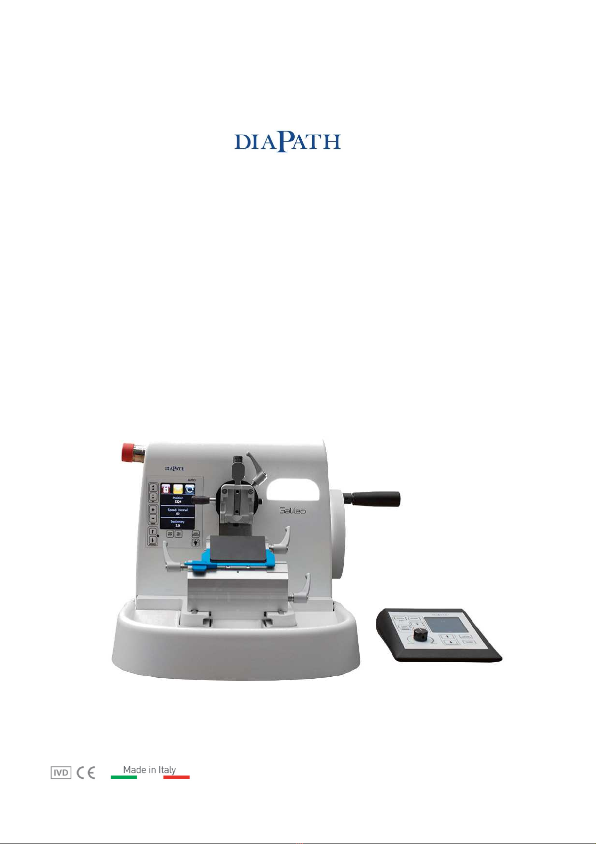
Galileo AUTO Series 2
Fully automatic rotary microtome
User Manual

2
Manufacturer:
Diapath S.p.A.
Via Savol ini,71
24057 Martinengo (BG) Italy
Tel. (+39)0363.986.411
Fax (+39)0363.948.000
www. iapath.com
info@ iapath.com

3
Manual information
This ocument is protecte by copyright laws; copyrights of this ocument belong to Diapath S.p.A.
It is strictly forbi en, full or in part, to mo ify this manual in absence of an explicit authorization.
Diapath S.p.A. is not oblige to regulate up ates of this manual, or to sen regularly reviewe or up ate versions of
this manual to its customers.
Information containe in this manual is subject to change without prior notice.
Diapath S.p.A. guarantees the accuracy of the information present in this manual as a result of thorough research; if
information is incorrect or unclear, please contact Diapath S.p.A. or the istributor. Diapath S.p.A. is not responsible for
any kin of material amages or other amages relate to non-compliance with in ications or specific information
present in this manual.
Diapath S.p.A. continuously a opts a evelopment policy an reserves the right to make changes an improvements to
any pro uct escribe in this manual without prior notice.
The serial number an ate of manufacture are reporte on the registration plate attache on the rear part of the
instrument.
Inspire to:
Galileo Galilei (Pisa, 15th February 1564 – Arcetri, 8th January 1642) was an Italian physician,
philosopher, astronomer an mathematician, consi ere the foun er of mo ern science. His name is
associate with important theories in ynamics an astronomy, such as telescope perfecting, which
brought him to make important astronomic observations an to intro uce the scientific metho .
Fun amental were his role in the astronomic revolution, support to the heliocentric system an to the
Copernican theory. His importance for the re-evaluation of science in general an of physics in particular
is connecte to iscoveries that he ma e through several experiments such as the principle of relativity,
the iscovery of Jupiter’s 4 moons, which were calle Galilean satellites, the inertia principle an the
iscovery that spee fall is the same for all bo ies in epen ently from material or mass
Manual Revision: Rev. 2
Edition date: 30
th
May 2018

4
Contents
Preface .......................................................................................................................................................................................... 5
Quality control.................................................................................................................................................................................... 6
Storage an han ling.......................................................................................................................................................................... 6
Safety information .............................................................................................................................................................................. 7
Definiton of a opte symbols .............................................................................................................................................................. 8
1
Packaging instruction .............................................................................................................................................. 9
2
Galileo AUTO Series 2 co ponents ........................................................................................................................ 15
2.1
Instrument overview ........................................................................................................................................... 15
2.2
Directional specimen hol er fixture with quick clamping system ............................................................................. 16
2.2.1 Object clamp for Supermega cassettes (optional) ......................................................................................... 17
2.2.2 Universal clamp (optional) .......................................................................................................................... 17
2.2.3 Quick-lock kit ............................................................................................................................................. 17
2.3 Knife hol er ................................................................................................................................................................. 18
2.4 Emergency stop push button ........................................................................................................................................ 18
2.5 Optionals ..................................................................................................................................................................... 18
2.5.1 Dynamic control pe al ................................................................................................................................ 18
2.6 Local boar ................................................................................................................................................................. 19
2.7 Remote control ............................................................................................................................................................ 20
2.8 Controls before the use ................................................................................................................................................ 21
2.9
Instrument features ............................................................................................................................................ 22
2.10
Part Supplie – Packing list .................................................................................................................................. 23
2.11
Technical ata .................................................................................................................................................... 24
3
Instru ent setting ................................................................................................................................................. 25
3.1
Placement an installation ................................................................................................................................... 25
3.1.1
Requirements for the placement .............................................................................................................. 25
3.1.2
Unpacking .............................................................................................................................................. 25
3.2
Instrument starting up ........................................................................................................................................ 26
3.3
Quick installation gui e ....................................................................................................................................... 27
4
Local board function .............................................................................................................................................. 30
4.1
Main screen ........................................................................................................................................................ 30
4.2
Alarm messages.................................................................................................................................................. 32
5
Re ote control function ........................................................................................................................................ 33
5.1
Main screen ........................................................................................................................................................ 33
5.2
Configuration menu ............................................................................................................................................ 34
5.2.1
Dynamic control pe al configuration ........................................................................................................ 35
5.2.2
Retraction configuration .......................................................................................................................... 36
5.2.3
Set Normal or Fast spee (Cutting win ow) .............................................................................................. 37
5.2.4
Language setting .................................................................................................................................... 37
5.2.5
Setting of number of sections in Multi stroke ............................................................................................ 38
5.2.6
Information screen ................................................................................................................................. 38
6
Microto e operation .............................................................................................................................................. 39
6.1
Semi-automatic sectioning mo e ......................................................................................................................... 39
6.2
Automatic sectioning with Remote control ............................................................................................................ 40
6.3
Automatic sectioning with Local boar .................................................................................................................. 41
6.4
Automatic sectioning with ynamic control pe al .................................................................................................. 42
6.5
Configuration of sectioning mo es ....................................................................................................................... 43
6.6
Rock mo e (Manual mo e) .................................................................................................................................. 44
6.7
Han wheel calibration system .............................................................................................................................. 44
7
Cleaning and aintenance ..................................................................................................................................... 45
7.1
LCD isplay cleaning ........................................................................................................................................... 45
7.2
External surfaces ................................................................................................................................................ 45
7.3
Instrument cleaning frequency ............................................................................................................................ 45
7.4
Knife hol er cleaning ........................................................................................................................................... 46
7.5
Clamp cleaning ................................................................................................................................................... 47
7.6
Section waste tray cleaning ................................................................................................................................. 47
7.7
Check orientation hea ........................................................................................................................................ 47
7.8
Fuses replacement .............................................................................................................................................. 47
8
Troubleshooting ..................................................................................................................................................... 48
9
WEEE Directive ....................................................................................................................................................... 49
9.1
Uninstallation an isposal .................................................................................................................................. 49
10
Diapath instru ent warranty ................................................................................................................................ 49

5
PREFACE
Destination of use
Galileo Series 2 is a motorize automatic rotary microtome for creating thin sections of paraffin embe e specimens. Suitable for
specimens of ifferent har ness once they are suitable for being sectione automatically.
The instrument may be operate by traine an qualifie staff only.
It is possible to set up all process parameters, such as: specimen coarse fee , cutting spee , cutting an trimming thickness.
The rea ing of this manual an the maintenance are essential to use the equipment avoi ing any angerous situation.
The operators must be a equately traine in its use an respect all safety rules an its use limits.
Traine an authorize Diapath S.p.A. staff will perform instrument maintenance, in case of failure or malfunction.
The microtome complies with CISPR 11 Class A rules: in case of omestic use, it may cause ra io interferences. In this case a
measurement an mitigation of such interference is necessary.
Before installing the instrument, an analysis of electromagnetic interferences must be performe .
Do not use the evice near sources of strong electromagnetic ra iations, such as ra iofrequency wave generators. In this case, the
ra iations may interfere with the normal functioning of the instrument.
The Instrument has been esigne accor ing to the legislative ecree 332/00 of 08th September 2000 “Accomplishment of 98/79/CE
irective of 27th October 1998 concerning in-vitro iagnostic me ical evices” respecting electromagnetic compatibility rules:
•ISO 9001(*) quality management system. Requirements
•ISO 13485(*) quality management system requirements for me ical evices. Requirements for regulatory purposes an
specific requirements of the application of ISO 9001 (*)
•UNI CEI EN ISO 14971(*) application of risks management to me ical evices
•UNI EN ISO 18113-3(*) In vitro iagnostic me ical evices. Information supplie by the manufacturer (labelling). Part 3: In
vitro iagnostic instruments for professional use
•UNI CEI EN ISO 15223-1(*) Symbols to be use with me ical evice labels, labelling an information to be supplie . Part 1:
General requirements
•EN 61326-1(*) Electrical equipment for measurement, control an laboratory use - EMC requirements Part 1: General
requirements
•EN 61326-2-6(*) Electrical equipment for measurement, control an laboratory use - EMC requirements. Part 2-6: Particular
requirements - In vitro iagnostic me ical evices (IVD)
•EN 61000-3-2(*) Electromagnetic compatibility (EMC) Part 3-2: Limits - Limits for harmonic current emissions. (equipment
with input current <= 16A per phase)
•EN 61000-3-3(*) + A1(*)+ A2(*) Electromagnetic compatibility (EMC) Part 3-3: Limits - Limitation of voltage fluctuations an
of flicker in low voltage supply systems for equipment with rate current <= 16A an not subject to con itional connection
•EN 61010-1(*) Safety requirements for electrical equipment for measurement, control an laboratory use. Part 1: General
requirements
•EN 61010-2-101(*) Safety requirements for electrical equipment for measurement, control an laboratory use. Part 2-101:
Particular requirements for me ical equipment for in-vitro iagnostics
•The LED light accor ing to stan ar EN62471 an classifie in 1 Risk Group Category
(*)
In the applicable e ition

6
Quality control
Diapath S.p.A. a opts quality management system ISO 9001(*) an ISO 13485(*) to esign, make an improve the technical-scientific
solution for the customer in me ical an iagnostic in vitro systems, assuring high quality services with the help of well-qualifie ,
motivate staff to contribute to the improvement of Diapath S.p.A. pro ucts.
Diapath S.p.A. consistently aims for customer satisfaction, trying to excee expectations an to treat the customer without any
iscrimination. Diapath S.p.A. assures the application of normative requirements.
Quality assurance of ata furnishe by Diapath S.p.A. is obtaine through these activities:
•Use only reference material
•Execution of proofs of the whole pro uction
•Correlation of ifferent results
The internal quality control foresees to monitor the most ifficult passages of an analytic process so as to verify their stability, assuring
that quality parameters estimate uring the vali ation or the checking of the metho are vali also for real instruments an that they
will not worsen over the course of time.
Diapath S.p.A. tests its own pro ucts accor ing to some internal proce ures, to re uce the possibility of anomalies uring the
operation.
To i entify an to service its own instruments, Diapath S.p.A. uses some internal proce ures which allow us to pro uction recor ing,
assembling recor ing, tests recor ing, serial number or batch co e an configuration recor ing
Instrument information
All information present in this manual regar only the evice shown on the cover.
On the instrument rear part, there is the registration plate with the serial number (Picture 1).
Storage an han ling
For correct conservation an functioning of the instrument, all the instructions provi e in this manual concerning the maintenance an
the installation must be respecte . Also the environmental requirements shown below shoul be respecte .
The instrument can work with 80% relative humi ity con itions for temperatures up to 31°C with a linear ecrease up to 50% at the
temperature of 40°C. Voltage variation cannot excee +/-10% the nominal value.
The instrument is planne only for internal use an up to 2000 m o.s. altitu e
Before turning on the instrument, it is a visable to leave the unit until it reaches environmental con itions
Storage an transp
ortation temperature range:
F
rom +5°C to +40°C
Storage humi ity:
80%
Working temperature range:
F
rom +5°C to +40°C
Picture 1 – Registration plate
Due to size an weight (
4
0 Kg), the han ling of the microtome must be perfo
rme by several people with
suitable
lifting means.
7
Safety information
Mentioned agree ent and graphic sy bols
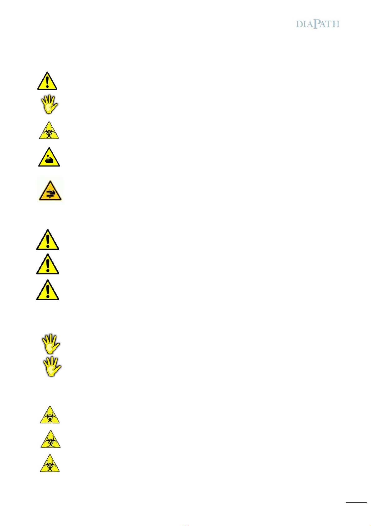
Danger - The anger instructions signal situations that might cause eath or serious lesions.
Caution - The caution instructions signal situations that might cause physical lesions to people or amages to
things.
Biohazard - The biohazar instructions signal situations that might cause the contamination of people or parts
involve in the process.
Cutting and shearing - The cutting an shearing instructions signal situations that might cause lesions to the
operator.
Crush hazard - The crush hazar instructions signal situations where bo y parts might be crushe by moving
parts.
Instruction of danger
Never isassemble, mo ify or repair the instrument or one of its parts without written authorization by Diapath
S.p.A.
Do not use any kin of ifferent power supply from the mentione ones
For use at voltages higher than 125V in the North American market electricity supply cables with NEMA 6-15P plug,
C13 plug connector an STJ cable with nominal capacity 13A 250V
must be use .
Instruction of caution
Do not place objects that are not involve in the use of the instrument.
The use of appropriate in ivi ual protection evices is recommen e (For instance: gloves).
Instruction of biohazard
Pay attention to the possible biological hazar of the parts involve in the process.
Special in ivi ual safety measures shoul be use by operators, in accor ance with the safety stan ar s in the
laboratories an pro uct safety ata sheets in relation to current rules.
Do not place objects that are not involve in the use of the instrument.
8
Safety training
All the operators must be traine to use the microtome safely. After such training the operators must have un erstoo that:
•The microtome must be connecte to a voltage source in accor ance with electrical ata label
•The use of the microtome ifferently from Diapath instructions might compromise its functioning an the safety of the operator
Users group
Galileo Series 2 must be use only by qualifie an well-traine operators.
All users can procee with the use of the evice only after rea ing this user manual an when all technical etails are familiar to them.
Co pliance with safety rules
All regulations relate to safety, local co es an instructions that appear in the manual or on the equipment must be carefully observe
to ensure personal safety an to prevent amages to both the microtome an to the equipment connecte to it. If the equipment is
use incorrectly, the protection provi e might be compromise .
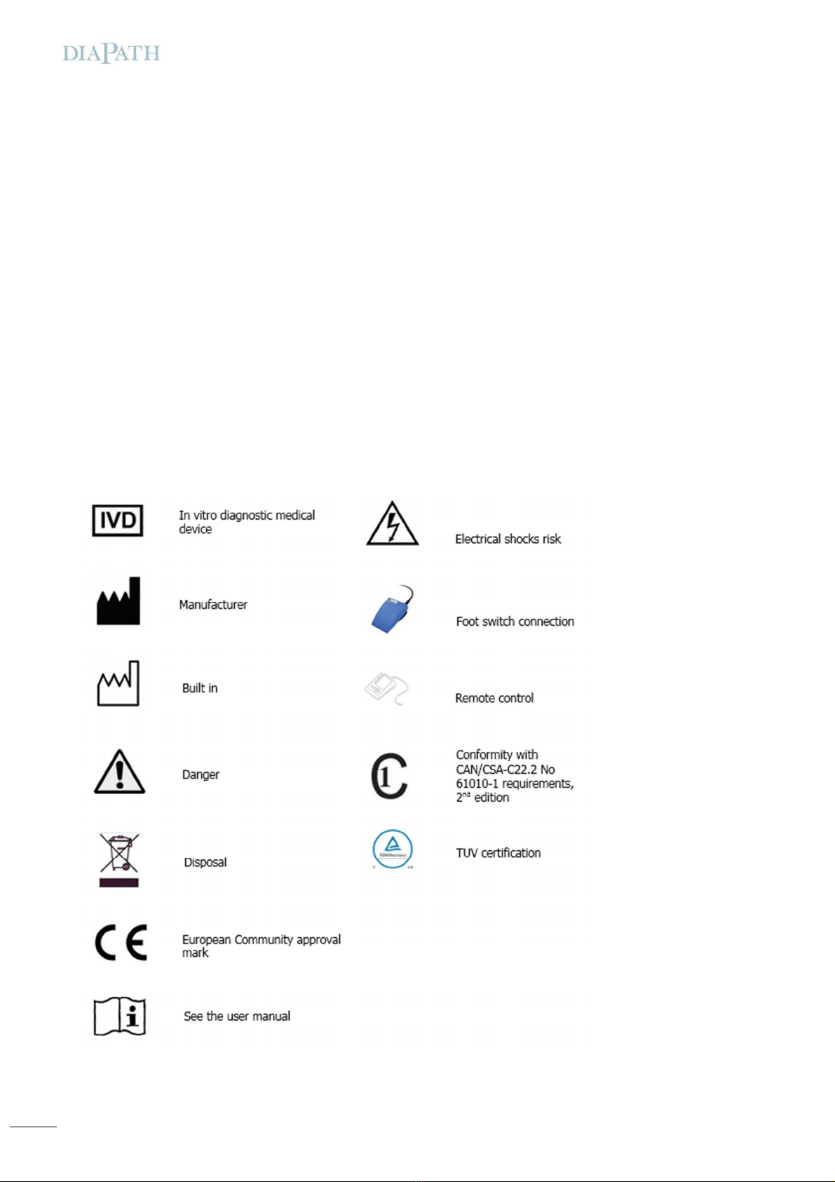
Definiton of a opte symbols

9
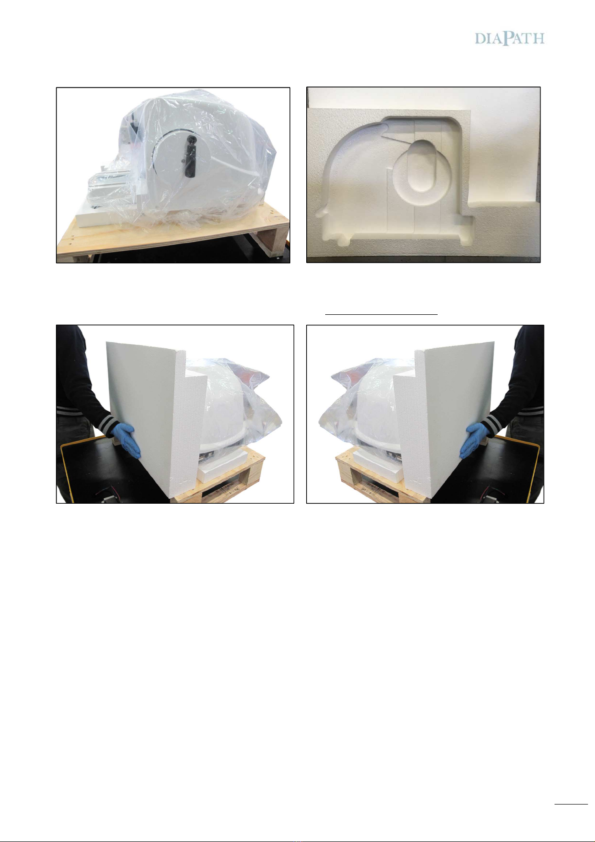
1Packaging instruction
Place the pallet an put the polystyrene strip on the base (Picture 2), in central position as shown in the picture. Clearance frontal si e
2 cm relate to the frame (Picture 3).
Place the microtome over the polystyrene base. Instrument clearance frontal si e must be at 3 cm from the frame (Picture3).
Instrument clearance lateral si es must be at 11 cm far from the pallet, both right an left si e.
Picture
2
Picture
3
3
c
3 c
11
c
11 c

10
Cover the instrument as shown in the picture. Avoi any kin of air bubble that may amage the instrument (Picture 4 -5 -6 -7).
Picture
4
Picture
5
Picture 6
Picture
7
11
Insert lateral si e an let them a here to the instrument (Picture 10- 11) - (Do not hit polystyrene high part).
Picture
9
Picture
1
0
Picture
1
0
Picture
1
1

12
Insert all elements as shown in the picture in the following or er:
Dynamic control pe al / knife hol er / remote control / waste tray / shelf (Picture 14-15-16).
Picture 13
Picture 15
Picture 12
Picture 14

13
Use the box (from the upper part) as shown in the picture (Picture 19 - 20).
Picture 20
Picture 16
Picture 19
Picture 17
Picture
18

14
Place polystyrene entirely over the close box (Picture 21) an cover using the woo box as shown below (Picture 22).
Close the cover an fix it to the pallet (Picture 23 - 24).
Box with available accessories (Picture 24B)
Picture 22
Picture 23
Picture 24
Picture 21
Picture 24B

15
2Galileo AUTO Series 2 components
2.1 Instru ent overview
Picture 25 – Microtome overview
Spacious shelf with
re ovable tray
E ergency stop push button Directional speci en holder fixture
with quick cla ping syste
Backlit panel
Local board
Section waste tray
Knife holder with knife
guard
Handwheel with
electronic lock
16
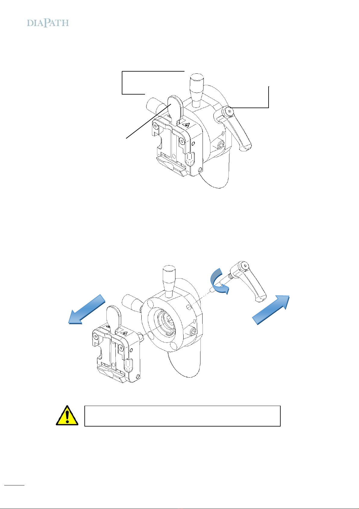
2.2 Directional speci en holder fixture with quick cla ping syste
To accomplish specimen orientation: loosen hea release lever (n.1) using a justing notches in or er to obtain the orientation esire
an clamp the release lever. For parallel alignment it is necessary to loosen release lever (n.1) an rotate notches one at a time until a
“CLICK” soun is note . “CLICK” soun in icates the Zero position achievement. Use both notches to obtain the resetting in both
irections, (Clamp lever n.1). To quickly replace the clamp, i.e. to replace the clamp for stan ar cassette an the one for macro-
cassettes, release lever (n.1), hol the clamp with one han an pull out the lever n.1. This proce ure allows the clamp to be pulle
out through the a justment proce ure. Insert the esire clamp, re-insert lever (n.1) an fix it in position.
Picture 26 – Universal cassette clamp
Adjusting setscrew with
position notch
Cassette release lever
Head release lever for
orientation
1
2
3
Picture 27 – Universal clamp cassette - Detail
ATTENTION
Before removing the clamp remove the bla e hol er
17
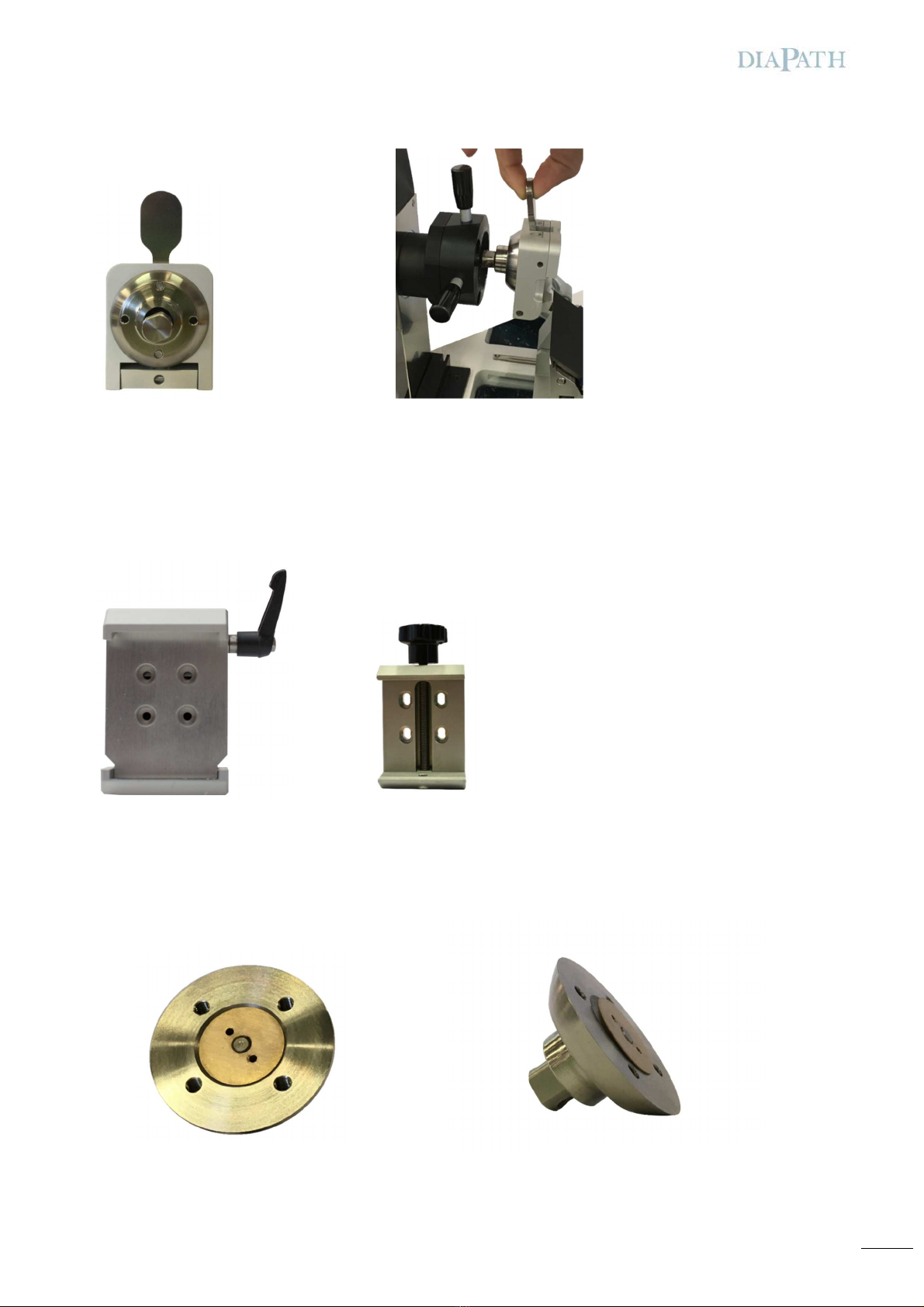
NOTE: Hol the clamp an then remove the unlocking screw
2.2.1 Object cla p for super ega cassettes (optional)
The clamp for mega-cassettes allows mega cassettes to be sectione with maximum length of 67mm.
2.2.2 Universal cla p (optional)
Universal clamp kit is a screw-clamp that allows the application of cassettes of ifferent imension an shape on the irectional
specimen hol er.
2.2.3 Quick-lock kit
Kit applie on a secon clamp that allows its installation an use of another specimen; it is necessary to loosen
unlock/orientation hea lever only
.
Picture
30
-
Clamp for
supermega
cassette
Picture
31
–
Universal clamp
Picture 33 – Quick-lock kit - Detail
Picture 28 – Orientation system - Detail Picture 29 – Orientatation system - Detail
Picture 32 – Quick-lock kit - Detail

18
2.3 Knife holder
To move the knife hol er towar the specimen, loosen lever 4, place the knife hol er an close the loosen lever.
To insert the bla e, loosen lever 3, let the bla e sli e within its own section, close the loosen lever.
Always cover cutting edge with knife guard when the instru ent is not in use.
To remove the bla e, use the ejector after releasing lever 3.
To move the bla e right an left, release lever 1, mount the bla e in the esire position an lock lever 1.
2.4 E ergency stop push button
The emergency stop push button is on the left si e of the microtome. If it is presse , it stops movement imme iately. The specimen
hol er can be move manually, allowing the user to operate for safety measures.
To restore microtome functionality, switch off the emergency stop push button an wait until the specimen hol er completes its
placement at the beginning of horizontal fee (position 0).
2.5 Optionals
2.5.1 Dyna ic control pedal
The ynamic control pe al allows to start the microtome at a spee proportionate to the pressure over the ynamic control pe al.
Plug the Dynamic control pe al connector into the specific area in the rear part of the instrument.
The ynamic control pe al replaces the potentiometer on remote panel that is inactive.
ATTENTION
Always lock the specimen an then the clamp. Before any operation regar ing the bla e, make sure that the
han wheel is locke an finger guar cover is in position.
Picture 34 – Knife hol er
1-Cla ping lever for
lateral displace ent
2
-
Knife guard with
ejector
3-Cla ping lever
for the blade
4- Cla ping lever
for knife holder
base
ATTENTION
Pay attention uring bla e han ling, they are very sharp an can causes serious lesions
Picture 35 – Dynamic control pe al
19
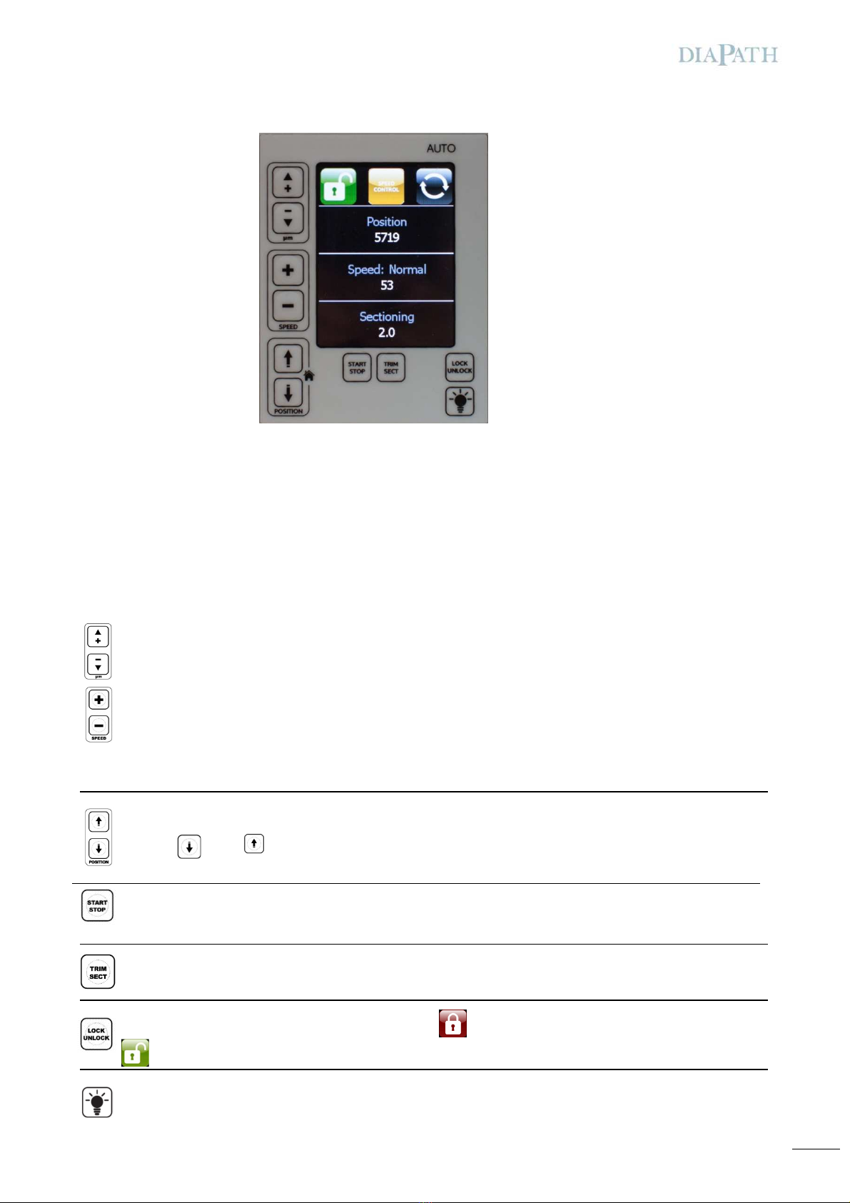
2.6 Local board
Local boar isplay shows microtome status an possible alarms an messages. Also, further sectioning information shown as:
•Position of specimen hol er referring to horizontal fee
•Movement spee (from 0 to 150)
•Sectioning/Tri ing mo e an its thickness in µm
The microtome can even be use without the Remote control. It is possible to set parameters an start movements by isconnecting it
from the microtome.
Display panel elements:
The Local boar is programme with the following keys:
Set section thickness. If Tri ing mo e is ON, changing tri ing thickness; otherwise changing Sectioning in thickness.
SPEED: spee of the specimen hol er. If presse , possibility to set up spee value from 1 (min) to 150 (max).
ATTENTION: These switches are active only if Remote control is not connecte to the microtome. Otherwise, spee control is possible
using the knob on Remote control.
POSITION: specimen hol er horizontal fee . If presse , moving the specimen hol er in the esire position.
Pressing , while is presse , the specimen hol er homing at zero point
START/STOP of microtome. To start, press twice within 1 secon ; to stop press once.
TRIM/SECT: if presse , allows selection of either Sectioning (Sect) or Tri ing (Tri ).
LOCK/UNLOCK of microtome. When microtome is in LOCKED position, the fee is mechanically locke . Press UNLOCK
icon to manually start microtome movement
Switching ON/OFF of backlit panel for an imme iate backlit or overlapping section evaluation. It checks also the right
association between cassette an sli e.
Picture 36 – Local boar isplay
20
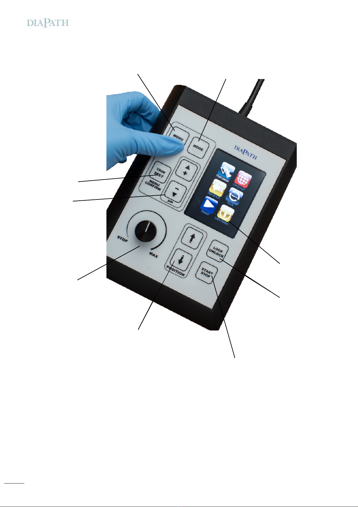
2.7 Re ote control
Remote control allows to set up microtome operating parameters. It isplays the main parameters concerning current
sectioning/trimming session:
•Sectioning/Tri ing with thickness in µm
•Cutting spee (from 0 to 150)
Picture 37 - Remote control interface
Electronic LOCK/UNLOCK
handwheel switch
START/STOP
Approach/Retracion of speci en
Speed
control knob to set cutting speed
(sectioning/tri ing)
Sectioning/tri ing setting key
Sectioning position button
MENU button
Sectioning thickness
ode and MENU surfing
Display LCD
Other diapath Laboratory Equipment manuals


Popular Laboratory Equipment manuals by other brands


Axygen
Axygen AXYPET AP-10 manual

Zymo Research
Zymo Research ZymoPURE Plasmid Miniprep instruction manual

Velp Scientifica
Velp Scientifica OHS 200 DIGITAL instruction manual

Waters
Waters SYNAPT G2 Operator's, overview and maintenance guide

Qsonica
Qsonica Sonicator Q700 Operation manual

Baker
Baker SterilGARD e3 SG404 Operator's manual