Caframo BDC1850 User manual

Caframo Real Torque Digital Stirrers
Power and Control
ENGLISH
Instruction Manual
pages 5-18
FRANÇAIS
Mode d’emploi
pages 19-32
ESPANÕL
Manual de instrucciones
páginas 33-46
DEUTSCH
Bedienungsanleitung
Seiten 47-60
RoHS
WEEE


501273 Grey Road 1
Georgian Bluffs ON N0H 2T0
Canada
Attn: Warranty Validation Department
Return Address
___________________________
___________________________
__________________________

Caframo Warranty Registration
Company Name________________________________________Contact Name_____________________________________________________
Address___________________________City___________________State/Prov______________Country______Zip/Postal Code______________
Telephone_____________________________Fax____________________________E-mail____________________________________________
Name of Dealer that supplied your Caframo Product__________________________Date of Purchase____________________________________
Model #___________________________Serial #______________________________________________________________________________
Please check the correct response and return to us via mail or fax to 800-209-6786. Or register on line at www.caframo.com/lab/warranty.php .
A. Frequency of use:
___Continuous Duty (1)
___Apporx 8 hrs/day (2)
___Approx. 4 hrs/day (3)
___Approx. 1 hr/day (4)
___Infrequent Use (5)
B. Viscosity of product:
___Low Viscosity
(1CPS - ie. Water) (1)
___Med. Viscosity
(1000CPS - ie. Paint, Oil) (2)
___High Viscosity
(5000 CPS - ie. Honey, Epoxies) (3)
___Very High Viscosity
(10,000 CPS - ie. Resins) (4)
C. Volumes mixed:
___0-1 liter (1)
___1-5 liters (2)
___5-10 liters (3)
___10 or more liters (4)
D. Average speed range used:
___1-1800 RPM (1)
___1800-3000 RPM (2)
___3000-6000 RPM (3)
___> 6000 RPM (4)
E. Type of paddle or impeller used:
F. Why did you purchase this product?
___Reputation (1)
___Pricing (2)
___Capabilities (3)
___Other (4)
G. Do you use other Caframo Products?
___Yes ____No
H. Do you use similar products from other
manufacturers?
___Yes ___No
If yes, who is the manufacturer?___________
I. What do you require in your facility that you
are having a difcult time obtaining? ________
______________________________________
______________________________________
_______________________
straight
blade
pivoting
blade
crossed
blade
colapsible
blade
propeller
blade
u-shaped
blade
square
blade

5
CONTENTS
Safety Instructions............................................................................................................... 6
General Instructions............................................................................................................. 7
Stirrer Approvals.................................................................................................................. 7
Packing List......................................................................................................................... 8
Description........................................................................................................................... 9
Technical Data................................................................................................................... 10
BDC Torque Capabilities................................................................................................... 11
BDC Specications............................................................................................................ 12
Keypad Membrane............................................................................................................. 12
Installation in the Laboratory............................................................................................. 13
Environmental Operating Conditions................................................................................ 13
General BDC Operating Instructions................................................................................. 14
Zero Torque Feature.......................................................................................................... 16
Cleaning and Service......................................................................................................... 17
Warranty and Product Liability......................................................................................... 18
On-Line Warranty Registration
www.caframo.com/lab/warranty.php
ZZZMN001
REV10

6
Safety Instructions
1. All operators must be familiar with the stirrer and should read this entire manual.
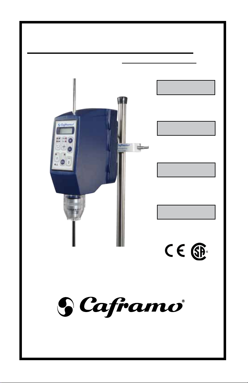
2. The stirrer must be securely xed to a stable support. Mount to a Caframo Stand
(Part Number A110) with a Caframo heavy duty clamp (Part Number A120). If
other stands or clamps are used, the unit must be secure and can not fall if tipped
up to ten degrees from the vertical.
3. The stirrer must be supplied with the rated voltage. See serial plate.
4. CAUTION: This is not an explosion proof stirrer. Do not use with highly
ammable or explosive materials.
5. Spinning paddles or impellers can cause severe personal injuries. Operators
must use extreme care and good judgement when mixing at any speed. The
BDC stirrers have higher torque capabilities than conventional stirrers.
6. All mixing paddles and impellers must be in good condition with straight shafts.
If the stirrer vibrates at high speeds check the paddle shaft for damage and repair
or replace it.
7. Extreme care must be taken when mixing chemicals so that no chemicals are
splashed outside the mixing vessel. Care must be taken when changing to faster
mixing speeds. On power up, the unit will display its set speed and will climb to
that speed when the start/pause button is pushed. Always start at lowest speed
if unsure of maximum safe speed.
8. Ensure that the mixing impeller does not contact the containing vessel.
9. Do not operate while standing in water. Keep the unit dry and do not immerse
any part, except the mixing paddle, into any liquids. Protect from splashing.
10. Ensure that no loose clothing, jewelry, or hair can become entangled in any
rotating parts. A fast spinning chuck can cause injury to an operator. Use chuck
guard provided when stirrer is in use.
11. Power can be interrupted to the stirrer by pressing the power button or by
disconnecting the mains cord. If rotating, this will cause the stirrer to stop and
will disconnect power to the stirrer’s internal drive circuit.
12. Shaft rotation can also be stopped by pressing the start/pause button. This does
not disconnect power to the stirrers internal drive circuit.
13. Wear safety goggles and suitable clothing when operating the stirrer.
14. Repairs must be carried out only by technicians authorized by Caframo.

7
Models Standards
BDC1850
BDC3030
BDC6015
BDC1850-220
BDC3030-220
BDC6015-220
General Instructions
1. Read all safety instructions.
2. Unpack the stirrer carefully. Ensure it is not damaged and verify the contents
against the packing list. If the stirrer is damaged or the contents do not
correspond with the packing list, notify your supplier immediately.
3. Read the manual carefully! Make sure that all users read this manual
thoroughly before operating the stirrer.
4. This instruction manual should always be kept readily available for reference.
5. For further questions or inquiries, please contact:
Caframo Limited
501273 Grey Road 1
Georgian Bluffs ON N0H 2T0, Canada
Tel: 519-534-1080
Toll free in USA and Canada: 800-567-3556
Fax: 519-534-1088
Website: www.caframo.com
Stirrer Approvals
CSA Canadian Standards Association
IEC Low Voltage Act
EMC Electromagnetic Compatibility Generic Immunity Standard
RoHS Restriction of Hazardous Substances (EU)
WEEE Waste Electrical and Electronic Equipment (EU)
CAN / CSA C22.2 (1010-1)
IEC1010
CE, IEC1010, EMC EN50081-1, EN50082-1
(EN61000-4-2,
EN61000-4-3, EN61000-4-4,
EN61000-4-5)
RoHS
WEEE

8
Packing List
Compare the contents of the shipment to the items on the following list to
ensure all parts are received with the unit. Do not discard the container and
packing materials until all parts are accounted for. It is recommended to keep
the original packaging for transportation and storage.
Description Order Number Quantity
Ultra Torque Stirrer, 115 volt BDC1850
or Universal Stirrer, 115 volt BDC3030
or Ultra Speed Stirrer, 115 volt BDC6015 1
or Ultra Torque Stirrer, 220 volt BDC1850-220
or Universal Stirrer, 220 volt BDC3030-220
or Ultra Speed Stirrer, 220 volt BDC6015-220
Calibration Certicate 1
Chuck with key 13C-SET 1
Chuck Guard CG-1 1
Instruction Manual ZZZMN001 1

9
Description
All Caframo stirrers are specically designed for professional use in the
laboratory and for use in industry to stir numerous liquids with various proper-
ties and applications. The BDC series of stirrers are available in six different
models.
BDC1850
BDC1850-220
rotates at 12 - 1800 rpm with a maximum torque of 568 Ncm
(50 in-lbs)
BDC3030
BDC3030-220
rotates at 20 - 3000 rpm with a maximum torque of 341 Ncm
(30 in-lbs)
BDC6015
BDC6015-220
rotates at 40 - 6000 rpm with a maximum torque of 170 Ncm
(15 in-lbs)
* The “220” models operate on 220-240 volt mains voltage.
The BDC stirrers use a digitally controlled high efciency brushless DC motor
which yields high torque over a very wide speed range. The speed is kept con-
stant with continuous feedback to the motor. The BDC stirrers are designed
for reliability and durability. There are no wear parts that require user service
during the normal life of the stirrer. There are no user serviceable parts.
The BDC stirrers incorporate smart logic for automatic transmission control.
This logic determines the appropriate speed range at which the stirrer should
operate. See Fig 1 and Fig 2 under BDC Torque Capabilities. The automatic
selection can be overridden by pressing the speed button.
With higher solution viscosities, more torque is required to stir at the same
speed. When the torque demands are outside the instrument’s range, the con-
trol logic slows down the stirrer until the torque comes within the instrument’s
range. If the torque demand is too great at the stirrer’s lowest possible speed,
the unit will automatically shut down.
The BDC stirrers are designed for safety. The unit comes on in “pause” mode
once power is activated. After a power interruption the stirrer remains off. The
stirrer’s speed will gradually ramp up to the desired set point after the start/
pause button is pressed.
All BDC stirrers have integrated electronic overload protection which ensures
no damage can occur to the electronics, motor or transmission when an over-
load situation occurs, such as too great a torque demand or unit overheating.
A chuck guard is supplied to place over the chuck. It protects the user from
the spinning chuck and also helps to protect the chuck from potential splashes.

10
Technical Data
Voltage 120 volts @ 60 Hz 230 volts @ 50/60 Hz
Installation Category
(in accordance with IEC664)
II II
Maximum Current Draw 3 Amps 3 Amps
Maximum Output Power 1/5 hp, 150 watts
Speed Readout LCD 4 digit display
Speed Readout Accuracy +/- 1 rpm or +/- 1% of reading
Torque Readout Accuracy +/- 12 N-cm (1 in-lb) or +/- 5% of reading
Maximum Operating Noise 70 dB(A) at 1 meter
Motor Type Brushless DC
Drive 2 stage transmission
Hollow drive shaft Nitrated P .30 with 10 mm (0.39”) diameter
bore for stirring impellers
13 mm (0.51”) outside diameter for drive chuck
Chuck Guard Length 67 mm, (2.64”)
Diameter 54 mm, (2.13”)
Molded of clear chemical resistant
polyurethane.
Seals Butyl Rubber
IP 42
Holding chuck 3 prong stainless steel. Maximum opening
10 mm (0.39”) diameter
Protection measures: 0
Class Protection device Recommended use
0 No additional protection Used only on equipment where failure of the
controls does not represent a hazard.
The operating conditions should be monitored at regular intervals.
BDC1850 / 3030 /6015

11
BDC Torque Capabilities
Stirrer
Low Speed High Speed
Min
Speed
rpm
Max
Speed
rpm
Peak
Torque
Ncm
Cont.
Torque*
Ncm
Min
Speed
rpm
Max
Speed
rpm
Peak
Torque
Ncm
Cont.
Torque*
Ncm
BDC1850 12 350 568 320 124 1800 114 75
BDC3030 20 584 341 190 206 3000 68 43
BDC6015 40 1168 170 85 412 6000 34 21
*Continuous torque at 50% of rpm range and 25 degrees Celcius.
Torque Conversion Table
In-lb to In-oz Multiply by 16 50 in-lb = 800 in-oz = 568 N-cm
In-lb to N-cm Multiply by 11.36 30 in-lb = 400 in-oz = 341 N-cm
N-cm to In-oz Multiply by 1.416 15 in-lb = 240 in-oz = 170 N-cm
Fig 1
Fig 2
High Speed
RPM
Torque (N-cm)
Max Torque
Continuous Operation @ 25 C
Continuous Operation @ 40 C
34 68 114
BDC 6015
BDC 3030
BDC 1850
29 57 95
23 46 77
17 35 58
12 23 39
380
600
1200
1800
3000
6000
BDC 1850
BDC 3030
BDC 6015
Low Speed
RPM
Torque (N-cm)
Continuous Operation @ 40 C
Continuous Operation @ 25 C
Max Torque
BDC 6015
BDC 3030
BDC 1850
170 339 568
139 277 462
107 213 355
75 150 249
43 85 142
BDC 1850
BDC 3030
BDC 6015
12
20
40
360
600
1200

12
Weight: 5 kg (11 lbs) Display Accuracy
Mounting Rod: 12.7 mm (½”) diameter Speed: ± 1 rpm or ± 1% of reading
140 mm (5¼”) long Torque: ± 12 N-cm or ± 5% of reading
Fig 3
Fig 4 Speed
- High Speed LED
- Low Speed LED
Display
- RPM LED
- Torque LED
Power
- Power LED
- Overload LED
Zero Torque
± (RPM)
Start/Pause
- Pause LED
BDC Specications
Keypad Membrane

13
Installation in the Laboratory
1. The stirrer must be securely xed to a stable support - e.g. clamped to an original
Caframo stand that is on a stable, level surface. See Safety Instructions.
CAUTION:
This is not an explosion-proof stirrer. Do not use
with highly ammable or explosive materials.
WARNING:
Be sure that the unit’s voltage is the same as the
supplied voltage. Information on the unit’s voltage
and current are located on the serial plate.
This unit must always be connected to a grounded
electrical outlet.
2. Chuck removal and attachment:
Loosen the set screw with the allen key found on the chuck key. Remove chuck.
To attach align the set screw with the pilot hole on the shaft. Tighten the set
screw with the allen key found on the chuck key. Make sure that the set screw
is rmly tightened. Open the chuck fully to prepare for impeller attachment.
3. Impeller attachment:
Insert the impeller shaft into the open chuck and adjust the impeller to a
maximum length of 25 cm (10 inches) [of a 40 cm (16 inch) shaft] to reduce
vibration. The hollow shaft allows the impeller shaft to come through the top of
the stirrer if necessary. Tighten the chuck’s outer ring by hand and then secure
with the chuck key. Install the chuck guard over the chuck.
Environmental Operating Conditions
All BDC stirrers must operate in the following conditions:
Indoors
1. Altitudes below 2000 meters.
2. Temperatures from 5 °C to 40 °C
3. Maximum relative humidity 80% for temperatures up to 31 °C decreasing
linearly to 50% relative humidity at 40 °C.
4. Mains supply as indicated under the technical specications.
5. Pollution degree 2 in accordance with IEC 664
“Normally only non conductive pollution occurs.
Occasionally, however, temporary conductivity caused by
condensation must be expected”

14
General BDC Operating Instructions
1. Make sure that the stirrer is securely mounted as specied in the installation
instructions. Also make sure that the mixing paddle or impeller is securely
attached in the desired position.
2. Connect the power cord to a grounded supply.
3. The stirrer is now ready for use to mix liquids and liquid/solid solutions. The
operator, ensuring that all safety instructions are followed must determine
appropriate impeller and container specications.
4. The stirrer can operate continuously if the torque demand falls below the
continuous torque operation line (see BDC Torque Capabilities Fig 1 and Fig
2). Should the ambient temperature be above 25 °C, then the 40 °C continuous
operation line must be used.
5. If the stirrer is used for an extended period of time above the appropriate
continuous temperature operation line (see BDC Torque Capabilities Fig 1 and
Fig 2), then it may shut down. The stirrer may be started after it has cooled
down.
Button Operating Functions
• Power - when power button is pressed for the rst time stirrer is activated in
“pause” mode. The set speed is displayed. RPM LED will be ashing indicating
this is a set speed.
• When stirrer is on the Power LED is on.
• When the Power button is pressed a second time, the stirrer is turned off. The
last set speed is remembered.
• Start/Pause - stops the stirrer when operating.
• Start/Pause returns the stirrer to the previous condition and previous display or
starts the stirrer if stopped.
• Pause LED is on when stirrer is paused and set speed is displayed.
• Display - When running, toggles display between speed (RPM) and torque
(N-cm). The LEDs indicate which parameter is displayed.
• When paused, the display will always show set speed.
• Speed - determines speed range (high speed/low speed) and overrides automatic
choice when allowable. The LEDs indicate which speed range is operating.
• + / - (RPM) Buttons - Press buttons once to increase / decrease set speed by one
rpm. Press and hold to increase / decrease speed at a greater rate.
• When unit is in pause, user can change the set speed by pressing the buttons.
• RPM LED will ash when displaying desired set speed and will be constant
when displaying actual speed.
• As unit is auto ramping to a faster speed the user can stop the increase in speed
by pressing the down arrow button. This changes the set speed to the present
actual value.
• As unit is auto ramping to a slower speed the user can stop the decrease in speed
by pressing the up arrow button. This changes the set speed to the present actual
value.

15
Indicator Lights
• High Speed / Low Speed LEDs - These indicate the stirrer’s set range.
• Overload LED - This indicator will ash when an overload condition is
approached. This indicator will remain on when an overload condition is
reached and the stirrer is shut down.
Overload conditions will occur when:
• The torque demand is outside the unit’s capabilities
(solution is too viscous).
• The unit overheats due to extended operation at very high
torque and/or speed demands.
When the overload condition is due to torque demand, the stirrer will automat-
ically reduce speed to reduce the load. If reduction in speed is not sufcient to
keep the load in the stirrer’s capable range, then the stirrer will shut down.
When the overload condition is due to overheating, the stirrer will not auto-
matically reduce speed. If the overload light is ashing and the speed has not
reduced from the set point, the load should be reduced by the operator.
In either case, if the stirrer completely shuts down due to an overload condi-
tion, it can be reset by powering off the stirrer. If the stirrer has overheated
then it must cool down before it can be reset.

16
Zero Torque Feature
Theory
Torque (turning force) is a measure of the force on an object such as a shaft or
a propeller. For example, pushing or pulling the handle of a wrench connected
to a nut or bolt produces a torque (turning force) that loosens or tightens the
nut or bolt. The units used to quantify torque are Newton-meters, Newton-
centimeters, or foot pounds.
In Mixing Applications the magnitude of torque depends on three quantities:
First, the speed in revolutions per minute; second, the diameter of the propel-
ler; and third, the viscosity of the material being mixed. Additionally, a small
amount of torque is required to move the mixing impeller. In small bench top
applications this additional or overhead torque is negligible and is generally
independent of the force required to mix material.
Zero Torque Feature
The zero torque feature allows the operator to null out the additional overhead
torque of the stirring apparatus similar to a tare feature on a scale. The feature
can also be used during the mixing process and allows the operator to see
change in torque caused by the change in material viscosity.
Zero Torque Operating Instructions
Run the stirrer at low speed for a ½ hour before zeroing torque. As the motor
warms up the torque can change slightly. Setting the torque when the stirrer is
warm will increase the accuracy.
1. Follow installation instructions. Before attaching the mixing impeller, press the
power button, ramp to the desired speed and press the start/pause button to start
the stirrer. Speed in rpm is displayed.
2. Press the display button. The stirrer displays actual torque. Note this cannot be
done unless the stirrer is running.
3. Press the Zero Torque button. The display now reads zero and the N-cm LED
will ash to indicate that the torque has been set to zero. Pause mixing. The
RPM LED will ash to indicate the stirrer has been paused.
4. Place the impeller into the chuck and then into the mixing vessel and press the
start/pause button to start mixing. The torque of the material being mixed will
now be displayed.
Follow all safety instructions when mixing.
Note:
At any time while mixing the torque display can be set to zero. Viscosity
changes can then be monitored as solutions change during the mixing process.
A negative number indicates a reduction in viscosity and a positive number
indicates an increase in viscosity.

17
Cleaning and Service
Cleaning
Using a mild soap and water solution, wipe the housing and control panel
of the stirrer with a damp cloth. Do not use chlorine bleach, chlorine-based
cleanser, abrasives, ammonia, steel wool, or scouring pads with metal content
or similar harsh solvents or abrasives. These may damage the surface of the
stirrer.
Service
Do not attempt to service or repair a Caframo stirrer. If the stirrer housing is
opened, the warranty becomes void. Contact Caframo for return authoriza-
tion and return instructions.
Clean the stirrer so that it is free from any materials which may be harmful.
Provide an MSDS or other safety data sheets for all chemicals used in con-
junction with this stirrer where appropriate. Place the stirrer and its parts into
the original packaging to protect and prevent damage during transport. Follow
shipping directions provided by Caframo when return is authorized and RMA
issued.
CAUTION: Failure to clean, service, and handle the stirrer as outlined
above can cause it to fail which could impair the safety of the user.
Other button functionality
• If the stirrer is powered off when in zero torque mode (N-cm LED ashing), the
stirrer will be in this mode when powered back on. If the stirrer is unplugged or
power is interrupted, the stirrer is reset and the feature will not be active.
• The speed can be changed any time – while the stirrer is running or in pause.
When the speed is changed, the speed in rpm is displayed while the speed is
adjusted. If torque was displayed prior to the change in speed, the display will
change back to displaying torque once the new speed is set.
• The zero torque feature can only be activated when the stirrer is running.
• When the zero torque button is pressed while the stirrer is running and rpm is
displayed, actual torque will be displayed. Press the zero torque button again,
the N-cm LED ashes indicating the stirrer is in zero torque mode.

Warranty and Product Liability
Warranty
Caframo warrants the herein described product of its manufacture for three
years from receipt of the equipment by the purchaser, against defects in
material and workmanship. Warranty registration is available on-line (www.
caframo.com/lab/warranty.php) or by completing the supplied warranty regis-
tration card. Mail or fax back as indicated.
This limited warranty covers parts and labor. In the event of a warranty claim,
contact Caframo. If the cause is determined to be a manufacturing fault, Cafra-
mo will repair or replace all defective parts to restore the unit to operation.
This warranty may only be altered by a specically published amendment. No
individual has authorization to alter the provisions of this warranty policy or
its amendments. Expendable items are not covered by this warranty. Dam-
ages due to corrosion, accidental breakage or submersion are not covered.
Product Liability
Under no circumstances shall Caframo be liable for indirect, consequential or
special damages of any kind.
Caframo reserves the right to make technical changes without prior notice.
18

19
TABLE DES MATIÈRES
Instructions de sécurité...................................................................................................... 20
Instructions générales........................................................................................................ 21
Approbations des agitateurs............................................................................................... 21
Liste de contrôle................................................................................................................. 22
Description......................................................................................................................... 23
Données techniques........................................................................................................... 24
Couple des agitateurs BDC................................................................................................ 25
Agitateurs BDC - Données techniques.............................................................................. 26
Plaque frontale................................................................................................................... 26
Installation dans le laboratoire........................................................................................... 27
Environnement nécessaire au fonctionnement des agitateurs BDC.................................. 27
Guide d’utilisation de l’agitateur BDC.............................................................................. 28
Fonction « Zéro couple » .................................................................................................. 30
Nettoyage et entretien........................................................................................................ 31
Garantie et responsabilité de produit................................................................................. 32
Enregistrement de la garantie en ligne
www.caframo.com/lab/garantie.php

20
Instructions de sécurité
1. Tous les utilisateurs devraient lire entièrement ce manuel et être familiarisés
avec l’agitateur.
2. L’agitateur doit être bien xé à un support stable. Monter l’agitateur sur
un support Caframo (numéro de pièce A110), avec une xation de qualité
industrielle Caframo (numéro de pièce A120). Si un autre support ou une autre
xation est utilisé, l’agitateur doit être bien xé et ne pas tomber si on l’incline
de dix degrés par rapport à la verticale.
3. L’agitateur doit être alimenté à sa tension nominale. Voir la plaque indicatrice.
4. ATTENTION : Cet agitateur n’est pas un appareil antidéagrant. Ne pas
l’utiliser avec des matières hautement inammables ou explosives.
5. En tournant, les palettes ou les hélices d’agitation peuvent provoquer de graves
blessures. Les utilisateurs doivent faire extrêmement attention et avoir un
jugement très sûr lorsqu’ils effectuent des mélanges à n’importe quelle vitesse.
Le couple des agitateurs BDC est supérieur à celui des agitateurs ordinaires.
6. Les palettes et les hélices d’agitation doivent être en bon état et l’axe sur lequel
elles sont montées doit être bien droit. Si l’agitateur vibre à haute vitesse,
vérier l’axe des palettes ou de l’hélice et le réparer ou le remplacer au besoin.
7. Faire extrêmement attention lorsque des produits chimiques doivent être
agités, pour qu’ils ne soient pas projetés hors du réservoir à agitation. User
de précaution lorsque la vitesse d’agitation doit être augmentée. Lorsqu’on
l’allume, l’agitateur afche la vitesse préétablie et accélère jusqu’à cette vitesse
lorsqu’on appuie sur la touche de pause. Toujours démarrer à la vitesse la plus
faible si l’on n’est pas sûr de la vitesse maximale de sécurité.
8. S’assurer que les palettes ou l’hélice ne touchent pas le réservoir à agitation.
9. Ne pas faire fonctionner l’agitateur dans l’eau. Le garder sec et n’immerger
aucune de ses parties dans quelque liquide que ce soit, sauf les palettes ou
l’hélice d’agitation. Prévoir une protection contre les projections.
10. S’assurer qu’aucun vêtement lâche, bijoux ou cheveux puisse être happé par
une pièce en rotation. L’utilisateur peut être blessé à cause d’un mandrin qui
tourne à grande vitesse. S’assurer que le couvercle de mandrin fourni est en
place lorsque l’agitateur est utilisé.
11. Appuyer sur la touche d’alimentation ou débrancher le cordon d’alimentation
pour couper l’alimentation de l’agitateur. Si l’agitateur tourne, l’alimentation
de son circuit interne d’entraînement est coupée.
12. Appuyer sur le bouton de pause pour arrêter la rotation de l’axe. Ceci ne coupe
pas l’alimentation du circuit interne d’entraînement de l’agitateur.
13. Porter des lunettes de sécurité et des vêtements adaptés lorsque l’agitateur doit
être utilisé.
14. Les réparations ne doivent être effectuées que par des techniciens autorisés par
Caframo.
Other manuals for BDC1850
2
This manual suits for next models
6
Table of contents
Languages:
Other Caframo Laboratory Equipment manuals

Caframo
Caframo BDC2002 User manual

Caframo
Caframo BDC1850 User manual

Caframo
Caframo BDC1850 User manual

Caframo
Caframo Petite Digital Stirrer BDC250 User manual

Caframo
Caframo Real Torque Digital Stirrers User manual

Caframo
Caframo BDC2002 User manual

Caframo
Caframo Petite Digital Stirrer BDC250 User manual
Popular Laboratory Equipment manuals by other brands

Diesse
Diesse Ves-Matic Cube 200 Service manual

Fisher Scientific
Fisher Scientific Fisherbrand 88861027 Operation manual

Tuttnauer
Tuttnauer ELCPVG-D Operation & maintenance manual

Adaptif Photonics
Adaptif Photonics A1XXX user guide

Nippon
Nippon FastGene FG-02 instruction manual

Metrohm
Metrohm 843 Pump Station manual