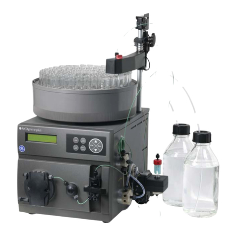
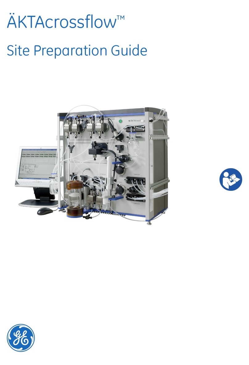
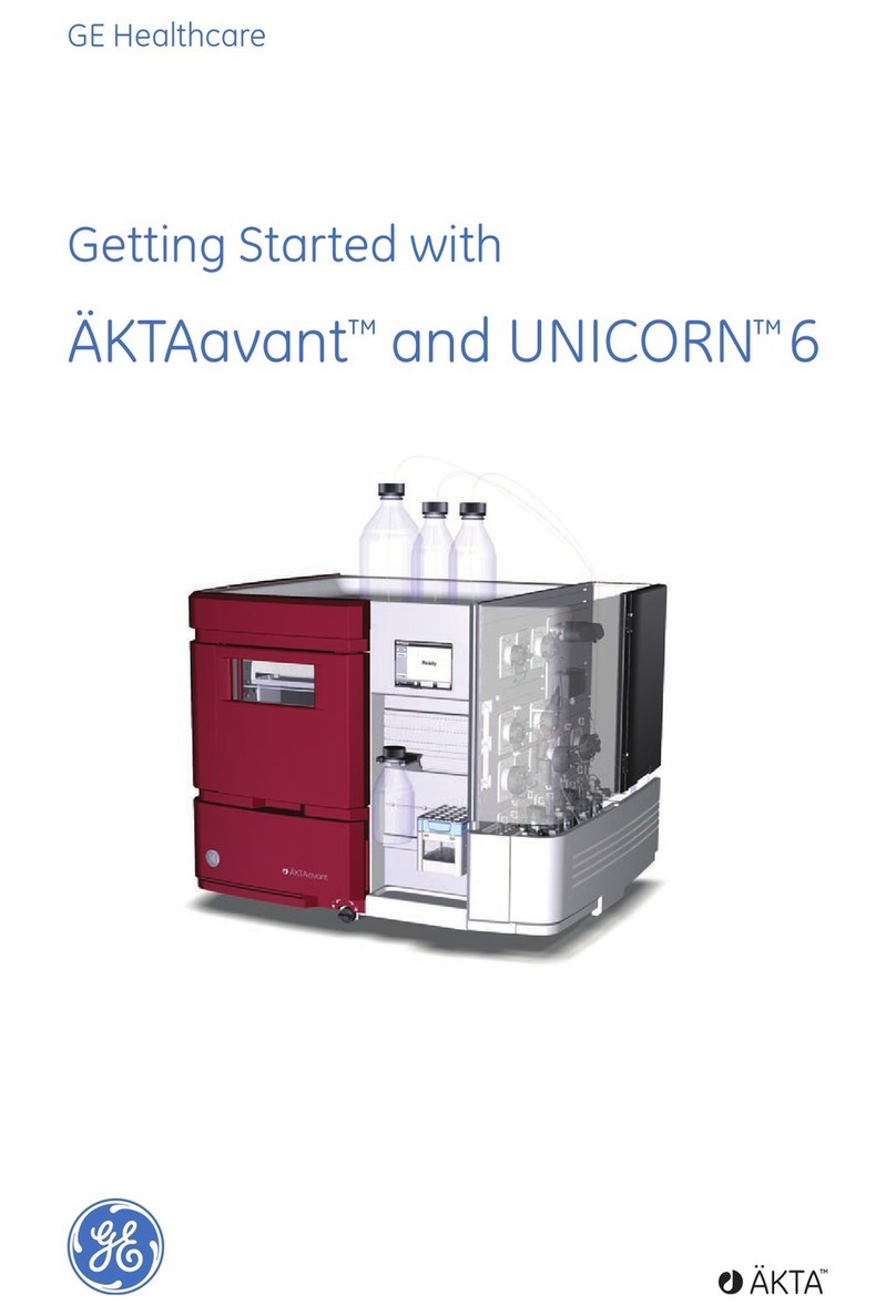
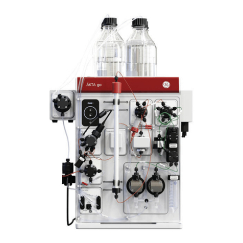
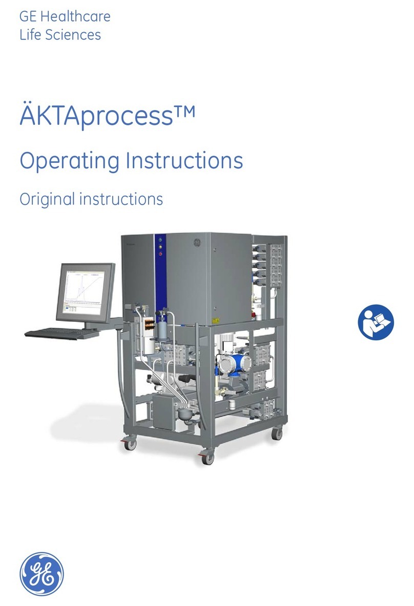
GE AKTA pilot 600 User manual

ÄKTA™pilot 600
User Manual

Table of Contents
41 Introduction ..........................................................................................................
51.1 About this manual ................................................................................................................................
61.2 Important user information .............................................................................................................
91.3 Associated documentation ..............................................................................................................
152 System description ..............................................................................................
162.1 Description of the ÄKTA pilot 600 instrument ..........................................................................
192.2 Flow path ..................................................................................................................................................
212.3 Accessories ..............................................................................................................................................
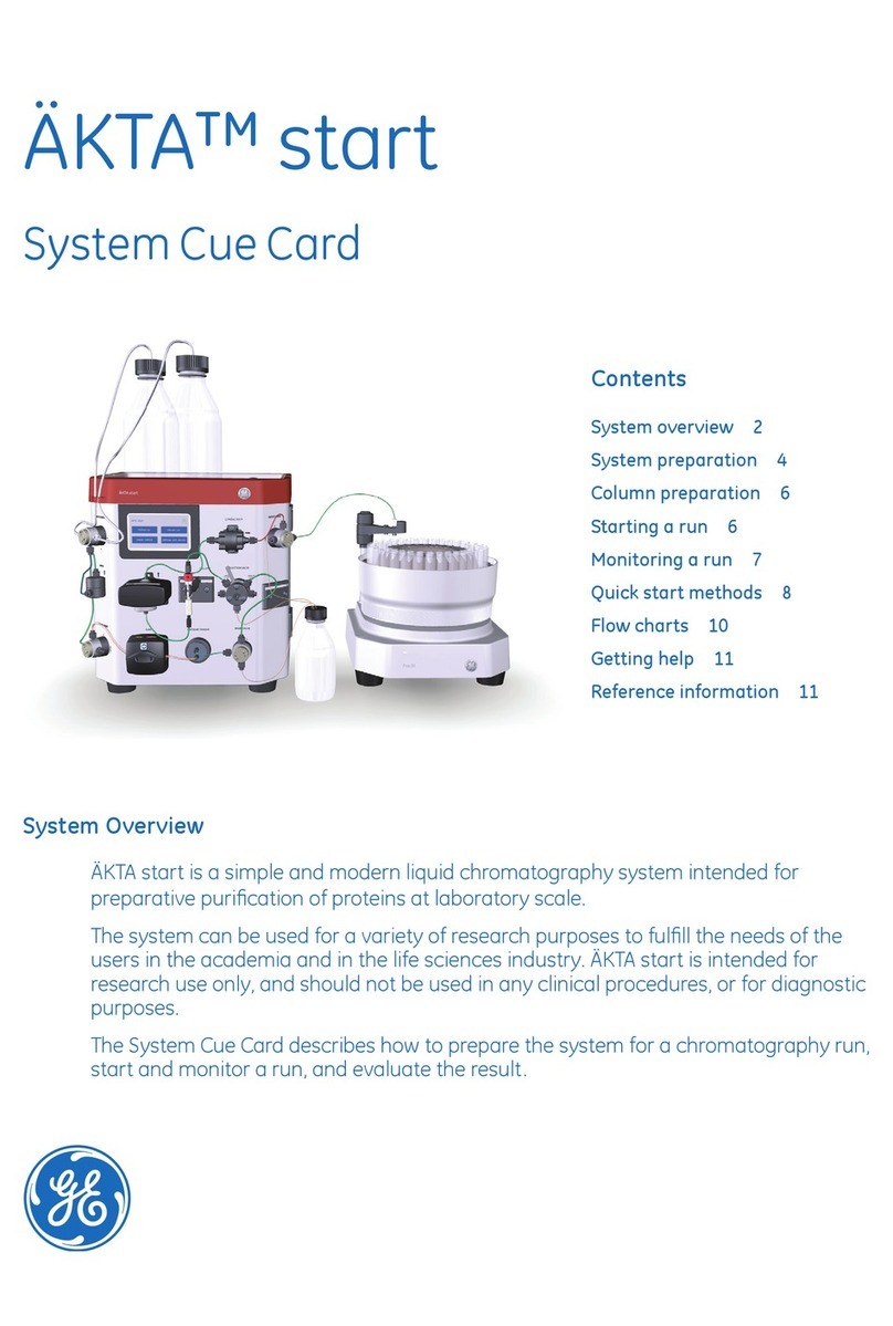
272.4 Instrument Configuration software .............................................................................................
293 Description of modules .......................................................................................
303.1 External air sensors (optional) .........................................................................................................
333.2 Inlet valves ...............................................................................................................................................
353.3 Pumps ........................................................................................................................................................
373.4 Flow restrictor ........................................................................................................................................
393.5 Mixer valve and mixer (optional) ...................................................................................................
413.6 Air trap valve and air trap .................................................................................................................
453.7 In-line filter (optional) ..........................................................................................................................
473.8 Column valve ..........................................................................................................................................
513.9 Conductivity monitor ..........................................................................................................................
533.10 UV monitor ...............................................................................................................................................
553.11 pH monitor (optional) .........................................................................................................................
573.12 Outlet valves ...........................................................................................................................................
594 Operation ..............................................................................................................
604.1 Sample application ..............................................................................................................................
614.1.1 Background considerations ......................................................................................................
634.1.2 Apply sample from a system inlet ..........................................................................................
684.1.3 Apply sample from a Superloop ..............................................................................................
714.2 Fractionation ..........................................................................................................................................
774.3 Intelligent packing ................................................................................................................................
814.4 Dual pump flow .....................................................................................................................................
844.5 Pressure control ....................................................................................................................................
874.6 Performing runs in a cold environment .....................................................................................
895 Maintenance .........................................................................................................
925.1 Maintenance manager ......................................................................................................................
935.2 Maintenance schedule .......................................................................................................................
955.3 Cleaning procedures ...........................................................................................................................
965.3.1 Clean the conductivity flow cell ...............................................................................................
985.3.2 Clean the UV flow cell ..................................................................................................................
1005.4 Calibration procedures ......................................................................................................................
1015.4.1 Reset the pressure sensors ........................................................................................................
2 ÄKTA pilot 600 User Manual 29274559 AA
Table of Contents
1045.4.2 Calibrate the conductivity monitor .........................................................................................
1095.5 Replacement procedures ..................................................................................................................
1115.5.1 Replace the pH electrode ............................................................................................................
1125.5.2 Replace the Mixer module ..........................................................................................................
1145.5.3 Replace the UV monitor flow cell ............................................................................................
1185.5.4 Replace valve fronts ......................................................................................................................
1196 Performance tests ...............................................................................................
1206.1 When to run performance tests ....................................................................................................
1226.2 How to run performance tests .......................................................................................................
1266.3 How to evaluate performance tests ............................................................................................
1287 Troubleshooting ...................................................................................................
1297.1 System leakage test failure ..............................................................................................................
1307.2 System backpressure test failure ..................................................................................................
1317.3 System test failure ................................................................................................................................
1337.4 Other performance tests ...................................................................................................................
1348 Reference information ........................................................................................
1358.1 Component volumes ...........................................................................................................................
1368.2 Ordering information ..........................................................................................................................
137Index .......................................................................................................................
ÄKTA pilot 600 User Manual 29274559 AA 3
Table of Contents

1 Introduction
About this chapter
This chapter contains important user information, descriptions of safety notices, intended
use of the ÄKTA pilot 600 system, and lists of associated documentation.
In this chapter
This chapter contains the following sections:
See pageSection
51.1 About this manual
61.2 Important user information
91.3 Associated documentation
4 ÄKTA pilot 600 User Manual 29274559 AA
1 Introduction

1.1 About this manual
Purpose of this manual
The User Manual provides you with in-depth instructions and information for using the
ÄKTA pilot 600 system. Basic instructions including important safety information are
given in the ÄKTA pilot 600 Operating Instructions.
Scope of this manual
The User Manual covers the ÄKTA pilot 600S (Standard) and ÄKTA pilot 600R (Regulatory)
instruments. The instrument is controlled by a PC running UNICORN system control
software version 7.3 or higher. For detailed information about the system control software,
see the UNICORN user documentation. For information about chromatography columns,
see the respective user manuals or instructions.
Typographical conventions
Software items are identified in the text by bold italic text. A colon separates menu levels,
thus File:Open refers to the Open command in the File menu.
Hardware items are identified in the text by bold text (for example, Power).
ÄKTA pilot 600 User Manual 29274559 AA 5
1 Introduction
1.1 About this manual

1.2 Important user information
Read the Operating Instructions
before using the product
All users must read the entire ÄKTA pilot 600 Operating Instructions before installing,
operating or maintaining the product.
Always keep the Operating Instructions at hand when operating the product.
Do not operate the product in any other way than described in the user documentation.
If you do, you may be exposed to hazards that can lead to personal injury and you may
cause damage to the equipment.
Intended use of the product
The ÄKTA pilot 600 system is a low-pressure automated liquid chromatography system
providing:
•precision transportation of fluids to and from chromatography columns of varying
sizes,
•detection and monitoring of UV absorbance, conductivity, and pH,
•fractionation of column eluate.
The system is intended for process development, scale up and scale down of processes,
as well as sanitary production of material for pre-clinical and clinical phases of applicable
scale. The working flow rate range is 0.1 to 600 mL/min, (or 600 to 1200 mL/min using
dual pump flow), at pressures up to 2 MPa (20 bar).
Process engineers, process operators and other trained laboratory personnel are the
intended users of the ÄKTA pilot 600 system.
The ÄKTA pilot 600 system shall not be used in any clinical procedures, or for diagnostic
purposes.
The ÄKTA pilot 600 system shall not be used in a potentially explosive atmosphere or for
handling flammable liquids.
6 ÄKTA pilot 600 User Manual 29274559 AA
1 Introduction
1.2 Important user information

Prerequisites
In order to follow this manual and use the system in the manner it is intended:
•The user should have a general understanding of how the computer and Microsoft®
Windows®work.
•The user must understand the concepts of liquid chromatography.
•The user must have read and understood the Safety instructions chapter in the
ÄKTA pilot 600 Operating Instructions.
•The ÄKTA pilot 600 system must have been installed according to the instructions
in the ÄKTA pilot 600 Operating Instructions.
•A user account must have been created according to the UNICORN™ Administration
and Technical Manual.
Safety notices
This user documentation contains safety notices (WARNING, CAUTION, and NOTICE)
concerning the safe use of the product. See definitions below.
WARNING
WARNING indicates a hazardous situation which, if not avoided,
could result in death or serious injury. It is important not to proceed
until all stated conditions are met and clearly understood.
CAUTION
CAUTION indicates a hazardous situation which, if not avoided,
could result in minor or moderate injury. It is important not to pro-
ceed until all stated conditions are met and clearly understood.
NOTICE
NOTICE indicates instructions that must be followed to avoid
damage to the product or other equipment.
ÄKTA pilot 600 User Manual 29274559 AA 7
1 Introduction
1.2 Important user information

Notes and tips
A note is used to indicate information that is important for trouble-free and
optimal use of the product.
Note:
A tip contains useful information that can improve or optimize your procedures.
Tip:
8 ÄKTA pilot 600 User Manual 29274559 AA
1 Introduction
1.2 Important user information

1.3 Associated documentation
Introduction
This section describes the user documentation that is delivered with the product, and
how to find related literature that can be downloaded or ordered from GE.
User documentation for
ÄKTA pilot 600
The user documentation listed in the table below is available in printed or on the web
PDF format. Translations of the Operating Instructions are provided on the User Docu-
mentation CD, together with the Product Documentation and Unpacking Instructions.
Main contentsDocumentation
Instructions needed to prepare and oper-
ate the ÄKTA pilot 600 system in a correct
and safe way.
ÄKTA pilot 600 Operating Instructions
System overview, site requrements, and
instructions for moving the system within
the same building.
Instructions for basic maintenance and
troubleshooting.
Additional information in order to get the
optimal performance from the system.
ÄKTA pilot 600 User Manual
(this document)
Functional description of modules.
Instructions for maintenance and trou-
bleshooting activities.
Information needed to prepare the site
for installation and use of the
ÄKTA pilot 600 system.
ÄKTA pilot 600 Site Preparation Guide
Instructions for handling the delivery
package and unpacking the
ÄKTA pilot 600 system.
ÄKTA pilot 600 Unpacking Instructions
Specifications and material conformity.ÄKTA pilot 600S Product Documentation
ÄKTA pilot 600 User Manual 29274559 AA 9
1 Introduction
1.3 Associated documentation

Product documentation binders
(Regulatory version only)
In addition to the user documentation, the documentation package supplied with
ÄKTA pilot 600R (Regulatory systems) also includes product documentation binders
containing detailed specifications and traceability documents, specific to the individual
system.
For more information about the ÄKTA pilot 600R instrument, see Standard and Regulatory
versions of the instrument, on page 16.
The following table provides some examples of documents that can be found in the
documentation package delivered with ÄKTA pilot 600R.
Purpose/ContentsAbbrevia-
tion
Document
Schematic overview of the process flow,
components and instruments and the
control system.
P&IDPiping and Instrumenta-
tion Diagram
Technical data for the system.GSGeneral Specification
Physical layout. Provides dimensional
data.
ADAssembly Drawing
Description of process-related compo-
nents, including wetted materials and
specifications.
BOMBill of Material
Declaration of Conformity for EU and/or
other regions.
DoCDeclaration of Conformity
List of spare parts available from GE.SPLSpare Part List
UNICORN documentation
The UNICORN documentation is listed in the following table. The documents are available
in the UNICORN Online Help and Documentation section of the on-line help (see Online
help, on page 11).
Main contentsDocumentation
•Video clips showing common workflows in the
Evaluation module.
•Overview of features of the Evaluation module.
Getting started with
Evaluation (accessed through
the online help in the
UNICORN Evaluation module)
10 ÄKTA pilot 600 User Manual 29274559 AA
1 Introduction
1.3 Associated documentation

Main contentsDocumentation
•Overview and detailed descriptions of the
method creation features in UNICORN.
•Workflow descriptions for common operations.
UNICORN Method Manual1
•Overview and detailed description of network
setup and complete software installation.
•Administration of UNICORN and the UNICORN
database.
UNICORN Administration and
Technical Manual1
•Overview and detailed descriptions of the
Evaluation Classic module in UNICORN.
•Description of the evaluation algorithms used
in UNICORN.
UNICORN Evaluation Manual1
•Overview and detailed description of the system
control features in UNICORN.
•Includes general operation, system settings and
instructions on how to perform a run.
UNICORN System Control
Manual1
Instructions for setting up and using the UNICORN
OPC server.
UNICORN OPC User Manual
1Current UNICORN version is added to the title of the manual.
Online help
Online help in UNICORN software may be accessed in three ways:
•Use the Help menu to access help on the current module and contextual help (help
on the currently context).
•Press the F1 key on the keyboard to open the contextual help for the current context.
•Click on the Help symbol if one is displayed. In general, Help symbols are shown
in dialog boxes.
All of these approaches open the online help in a help browser (illustrated below) that
supports access to UNICORN documentation and navigation among help topics using
browse, search and index functions.
ÄKTA pilot 600 User Manual 29274559 AA 11
1 Introduction
1.3 Associated documentation

Important information
In some contexts, important and supplementary information about settings is presented
in tooltips, marked by the information symbol .
Hover over the symbol to show the tooltip.
12 ÄKTA pilot 600 User Manual 29274559 AA
1 Introduction
1.3 Associated documentation

Help for specific instructions
To access help for specific instructions in System settings and Manual instructions and
for text instructions in the Method Editor module, select the instruction and press F1.
Navigation among help topics is not supported from help displayed in this way.
User documentation and other
literature on the web
User documentation and other literature related to ÄKTA pilot 600 system may be
downloaded from the web. Follow the steps below to access the documentation.
ActionStep
Go to www.gelifesciences.com/aktapilot.1
Navigate to RELATED DOCUMENTS.2
Select the type of document and download the chosen literature.3
ÄKTA pilot 600 User Manual 29274559 AA 13
1 Introduction
1.3 Associated documentation

Access documentation from
mobile units
Scan the code using your mobile phone or tablet computer to access the product page
for ÄKTA pilot 600. Select documents to download under RELATED DOCUMENTS.
14 ÄKTA pilot 600 User Manual 29274559 AA
1 Introduction
1.3 Associated documentation

2 System description
About this chapter
This chapter gives an overview of the ÄKTA pilot 600 instrument, available accessories,
and the Instrument Configuration software.
In this chapter
This chapter contains the following sections:
See pageSection
162.1 Description of the ÄKTA pilot 600 instrument
192.2 Flow path
212.3 Accessories
272.4 Instrument Configuration software
ÄKTA pilot 600 User Manual 29274559 AA 15
2 System description

2.1 Description of the ÄKTA pilot 600 instrument
Introduction
This section gives an overview of the instrument and the available modules.
Standard and Regulatory
versions of the instrument
The ÄKTA pilot 600 instrument is available in two versions:
•ÄKTA pilot 600S, Standard instrument, with the possibility to install optional modules.
•ÄKTA pilot 600R, Regulatory instrument. The ÄKTA pilot 600R system is supplied fully
configured according to the purchase specifications, and is tested at the factory.
ÄKTA pilot 600R is delivered with the additional instrument specific, detailed docu-
mentation. Installing, removing or moving modules will make the documentation
invalid.
The instrument version is indicated on the front panel as shown in the illustration below:
600R
600S
Regulatory instrumentStandard instrument
ÄKTA pilot 600 instrument front
panel
The following illustration shows an example of the ÄKTA pilot 600 instrument, with all
types of modules installed. The location of modules can vary, depending on customer
requirements. Optional modules are indicated in the table.
16 ÄKTA pilot 600 User Manual 29274559 AA
2 System description
2.1 Description of the ÄKTA pilot 600 instrument

1
2
3
4
5
7
6
8
9
12 13
11
16
14
15
17
18
19
20
21
22
2325 24
10
Optional (*)LabelDescriptionPart
-Control panel. The instrument version is indicated below
the control panel: 600S (red) or 600R (blue)
1
*pHpH monitor2
Outlet Valve
W/1 2 3
Outlet valve 1-3, port 1 can be used for waste3
*Outlet Valve
456
Outlet valve 4-64
CondConductivity monitor5
*Outlet Valve
789
Outlet valve 7-96
*Cond Pre-col-
umn
Pre-column Conductivity monitor7
ÄKTA pilot 600 User Manual 29274559 AA 17
2 System description
2.1 Description of the ÄKTA pilot 600 instrument

Optional (*)LabelDescriptionPart
Column ValveColumn valve, including pre- and post-column pressure
sensor
8
-Bottles for pump rinsing solution9
Inlet Valve
A1 A2 A3
Inlet valve A1-A310
*Inlet Valve
A4 A5 A6
Inlet valve A4-A611
Inlet Valve
B1 B2 B3
Inlet valve B1-B312
*Inlet Valve
B4 B5 B6
Inlet valve B4-B613
-Fixed plastic feet14
-Adjustable feet15
Pump ASystem pump A16
Pump BSystem pump B17
-Flow restrictor, including system pressure sensor18
*MixerMixer module19
*Mixer ValveMixer valve20
Air Trap ValveAir trap valve, including air sensor21
-Air trap22
-ON/OFF button23
*-In-line filter (stainless steel filter housing shown)24
UVUV monitor25
18 ÄKTA pilot 600 User Manual 29274559 AA
2 System description
2.1 Description of the ÄKTA pilot 600 instrument

2.2 Flow path
Introduction
This section gives a generalized overview of the flow path in the ÄKTA pilot 600 instrument.
The flow path in a specific instrument is determined by the modules that are installed
and by the current settings in UNICORN software. Several functions such as the mixer,
air trap and columns can be switched in or out of the flow path as required by setting
to In-line or By-pass in the software.
Flow diagram
The following illustration shows a schematic diagram of the flow path. Optional compo-
nents are marked with dashed outlines.
B1
B2
B3
A1
A2
A3
A5
A4
A6
A8
A7
A9
B5
B4
B6
1/W
2
3
P CondCond UV pH
P
AP
R
B
A
1
IP
W2
2
4
5
6
13
14
15
1
2
3
4
5
6
8
9
7
11
10 12 13 14 15
FunctionPart
Inlet valve A with 3 ports. Can be expanded to 9 ports with optional inlet
valves.
1
Inlet valve B with 3 ports. Can be expanded to 6 ports with optional inlet
valves.
2
System pump A3
System pump B4
Flow restrictor and system pressure sensor5
Mixer and mixer valve (optional)6
Air trap7
ÄKTA pilot 600 User Manual 29274559 AA 19
2 System description
2.2 Flow path

FunctionPart
Air trap valve including air sensor8
In-line filter (optional)9
Pre-column Conductivity monitor with temperature sensor (optional)10
Column valve including pre-column and post-column pressure sensors11
Conductivity monitor with temperature sensor12
UV monitor13
pH module (optional)14
Outlet valve with 3 ports. Can be expanded to 15 ports with optional outlet
valves.
15
20 ÄKTA pilot 600 User Manual 29274559 AA
2 System description
2.2 Flow path
This manual suits for next models
2
Table of contents
Other GE Laboratory Equipment manuals

GE
GE ImageQuant LAS 500 Operating instructions

GE
GE LOGIQ S7 Expert User manual

GE
GE AKTA GO User manual

GE
GE SE 250 Mighty Small II User manual

GE
GE akta start Guide

GE
GE Amersham Imager 600 User manual

GE
GE Monitor UV-900 User manual

GE
GE LOGIQ S8 User manual

GE
GE Amersham Imager 680 User manual

GE
GE SEMIPHOR TRANSPHOR Series User manual