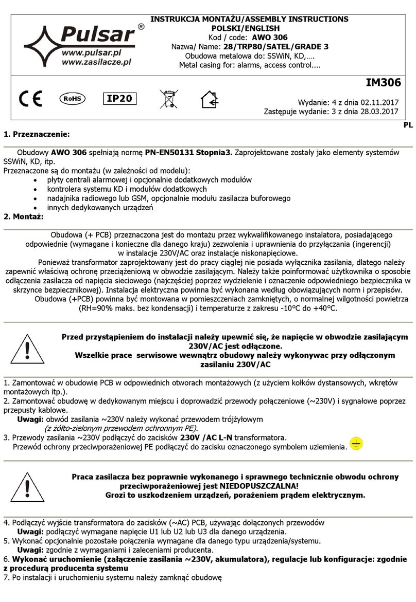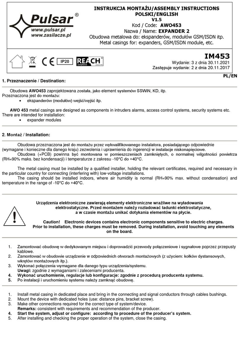
1. Zamontować w obudowie PCB w odpowiednich otworach montażowych (z użyciem kołków dystansowych, wkrętów
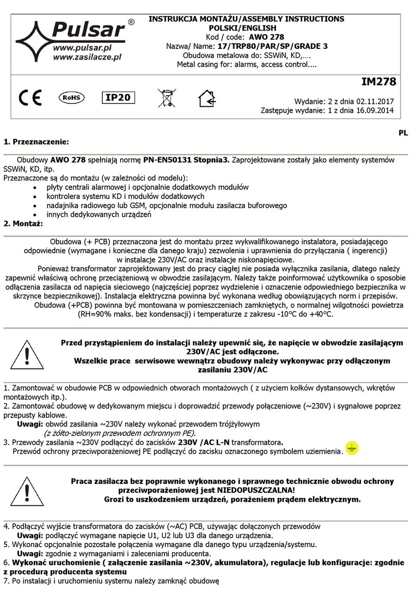
montażowych itp.).
2. Zamontować obudowę w dedykowanym miejscu i doprowadzić przewody połączeniowe (~230 V) i sygnałowe poprzez
przepusty kablowe.
Uwagi: obwód zasilania ~230 V należy wykonać przewodem trójżyłowym
(z żółto-zielonym przewodem ochronnym PE).
3. Przewody zasilania ~230V podłączyć do zacisków 230 V AC L-N transformatora.
Przewód ochrony przeciwporażeniowej PE podłączyć do zacisku oznaczonego symbolem uziemienia.
1. Mount the PCB (control panel, etc) with dedicated holes (using pins, screws etc.)
2. Mount enclosure in a dedicated location, lead connection wires (~230 V) and signal cables through cable openings.
Remarks: supply circuit ~230 V should be carried out with three-core cable
(with yellow-green protective PE conductor).
3. Supply conductors ~230V should be connected to 230 V AC L-N terminals of the transformers.
Protective conductor should be connected to the terminal marked with grounding symbol.
Praca zasilacza bez poprawnie wykonanego i sprawnego technicznie obwodu ochrony
przeciwporażeniowej jest NIEDOPUSZCZALNA!
Grozi to uszkodzeniem urządzeń, porażeniem prądem elektrycznym.
Caution! Operating the power supply without properly made and technically
operational electric shock protection circuit is IMPERMISSIBLE!
This creates hazard of equipment damage and risk of electric shock.
4. Podłączyć wyjście transformatora do zacisków (~AC) PCB, używając dołączonych przewodów
Uwagi: podłączyć wymagane napięcie U1 lub U2 lub U3 dla danego urządzenia.
5. Wykonać opcjonalnie pozostałe połączenia wymagane dla danego typu urządzenia/systemu.
Uwagi: zgodnie z wymaganiami i zaleceniami producenta.
6. Wykonać uruchomienie (załączenie zasilania ~230 V, akumulatora), regulacje lub konfiguracje: zgodnie z
procedurą producenta systemu.
7. Po instalacji i uruchomieniu systemu należy zamknąć obudowę.
4. Connect the output of transformer to the terminals (~AC) on the PCB, using installed cables
Remarks: connect required voltage U1 or U2 or U3 (secondary winding voltage) for the correct device.
5. If necessary, make other connections required for the correct type of system / device.
Remarks: consistent with requirements and recommendation of equipment producer.
6. Start the system (switch on ~230 V, battery), adjust or configure: according to procedure of the producer’s
system.
7. After installing and checking the proper operation of the system, close enclosure.
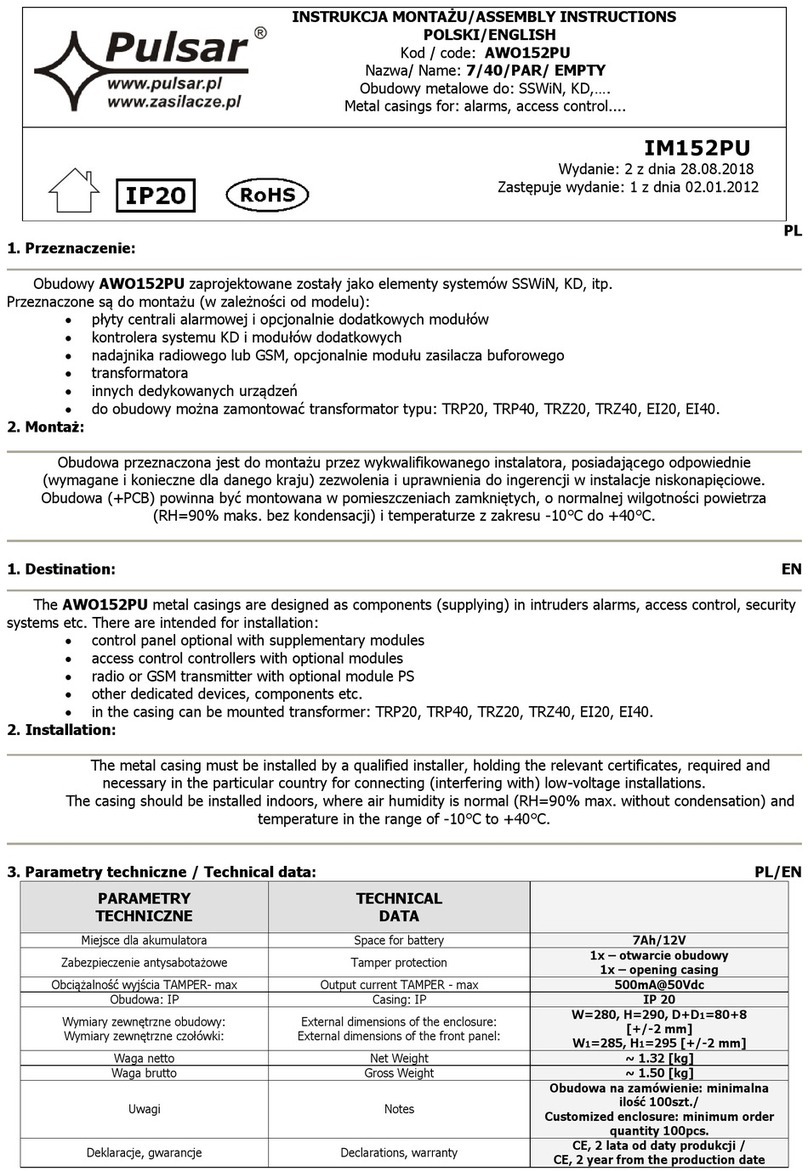
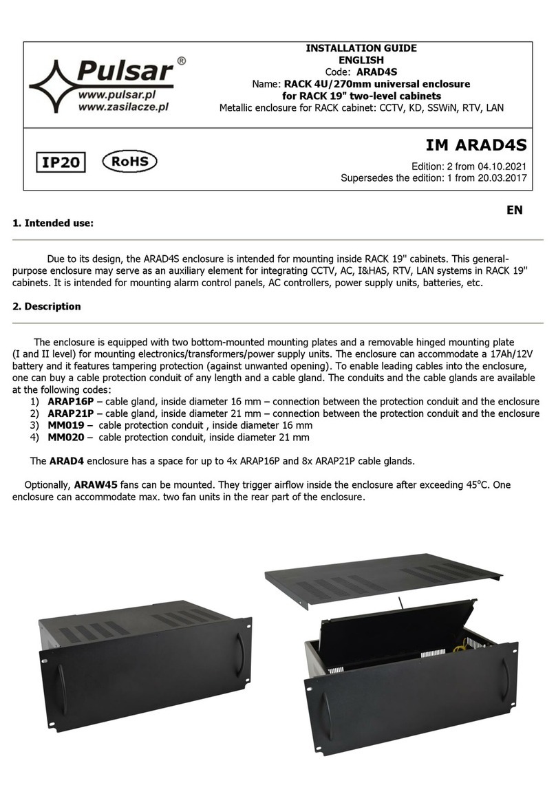
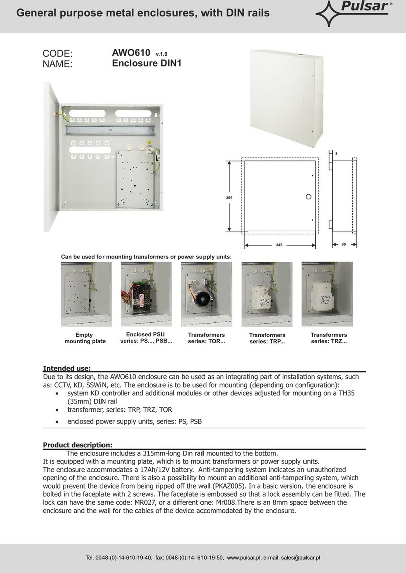
3. Parametry techniczne / Technical data:
Zabezpieczenie antysabotażowe
1 x mikrowyłącznik: otwarcie obudowy, 0,5 A; 50 V DC max.
NC –styki normalnie zwarte
Opcjonalnie: 1 x mikrowyłącznik: oderwanie od ściany,
0,5A; 50 V DC (wymagany PKAZ066)
1 x microswitch: enclosure opening 0,5 A; 50 V DC max. NC
–normally closed contacts
Optionally: 1 x microswitch: detachment form wall, 0,5A; 50
V DC (required PKAZ066)
Obciążalność wyjścia TAMPER- max
Output current TAMPER –max
Wilgotność względna RH – max.
Relative humidity RH –max.
Wymiary zewnętrzne obudowy:
External dimensions of enclosure:
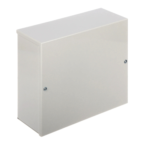
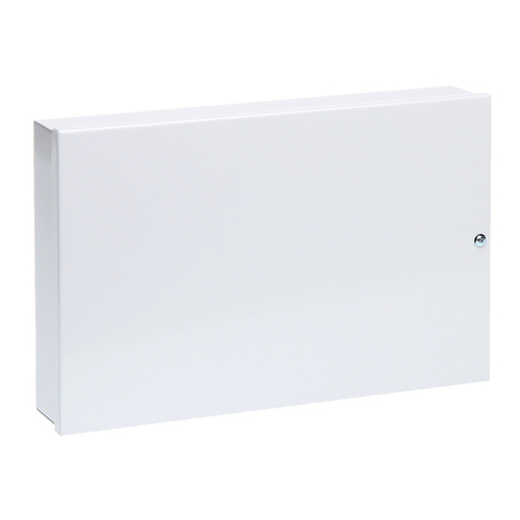
W=250, H=250, D+D1=80+8 [+/-2 mm]
