AWZ637
Table 7. Operating parameters.
20%...90%, without condensation
Vibrations during operation
Impulse waves during operation
Vibrations and impulse waves during transport
According to PN-83/T-42106
2. Installation.
2.1 Requirements.
The buffer PSU shall be mounted by a qualified installer with appropriate permissions and qualifications
for 230 V AC installations and low-voltage installations (required and necessary for a given country). Unit should be
mounted in confined spaces, in accordance, with normal relative humidity (RH=90% maximum, without condensing) and
temperature from -10°C to +40°C. The PSU shall work in a vertical position that guarantees sufficient convectional air-
flow through ventilating holes of the enclosure.
The unit should be mounted in a metal enclosure (cabinet) in a vertical position so as to ensure free, convection
air flow through the vents. In order to meet the EU requirements, follow the guidelines on: power supply, enclosures and
shielding: - according to application.
As power supply is designed for a continuous operation and is not equipped with a power-switch, therefore, an
appropriate overload protection in power supply circuit should be provided. Moreover, the user shall be informed about
the method of unplugging (most frequently through separating and assigning an appropriate fuse in the fuse-box).
The electrical system shall follow valid standards and regulations.
2.2 Installation procedure.
CAUTION!
Before installation, cut off voltage in 230 V power-supply circuit. To switch power off, use an
external switch, in which distance between contacts of all poles in disconnection state is not less
than 3mm.
It is required to install an installation switch with a nominal current of 6 A in power supply
circuits outside power supply unit.
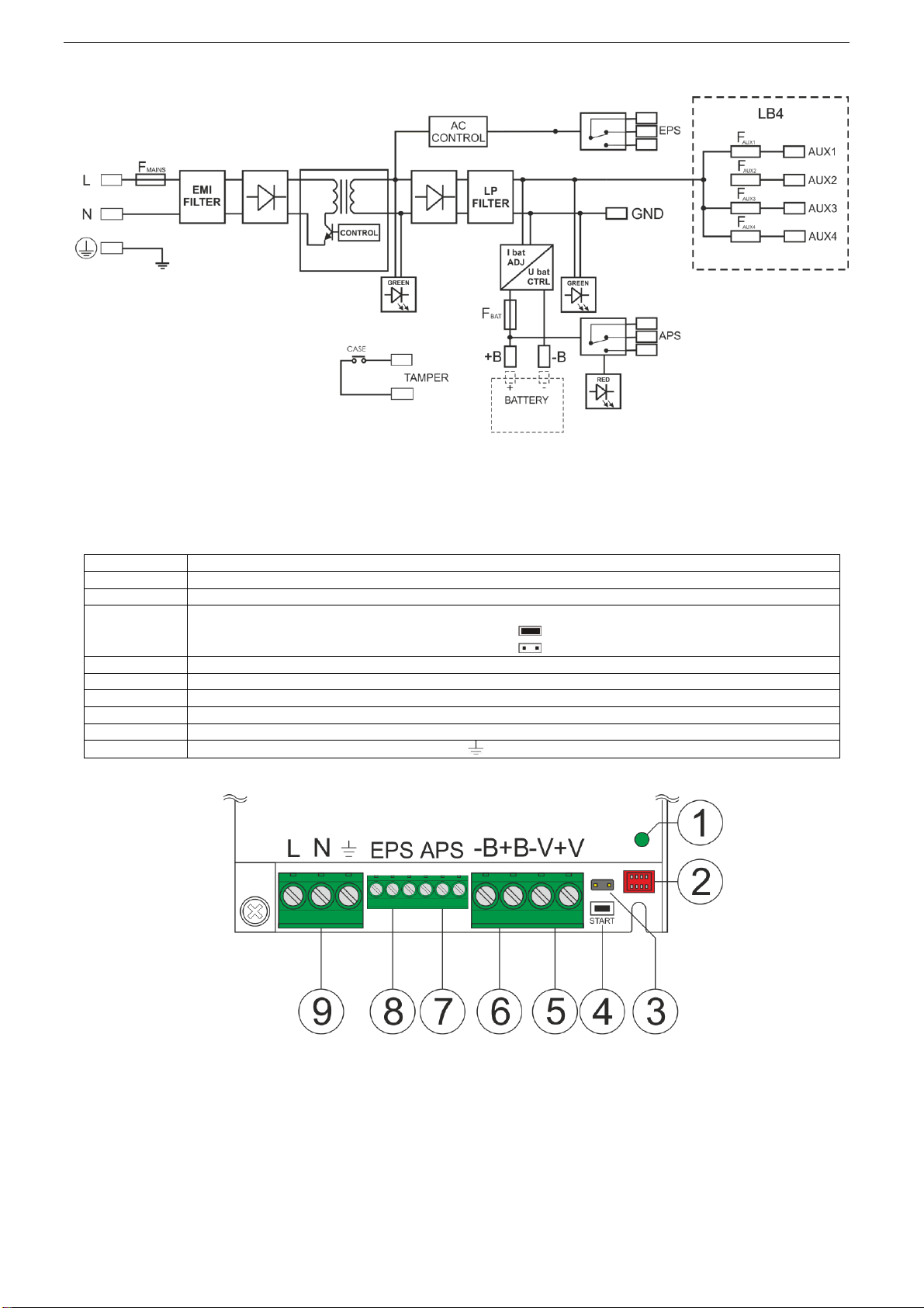
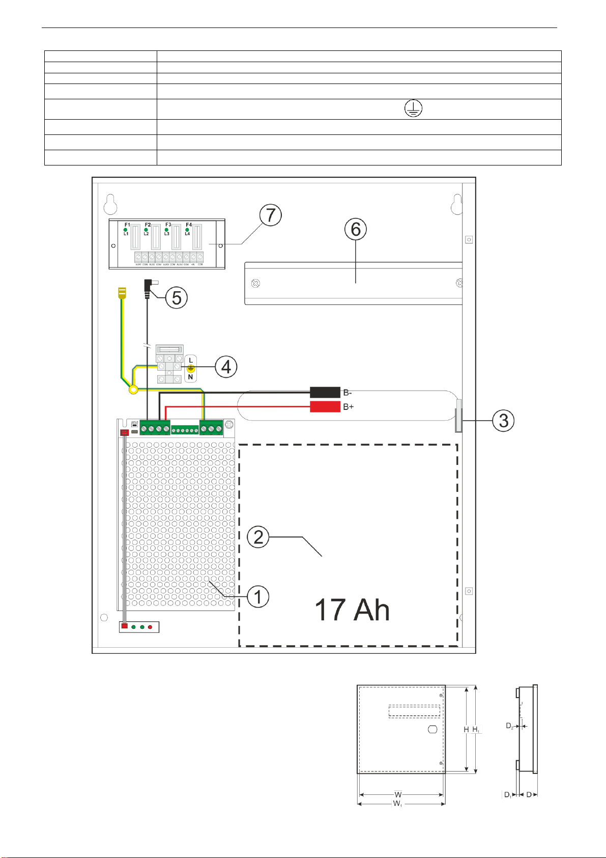
1. Mount the PSU in a selected location and connect the wires.
2. Connect power cables (~230 V) to L-N clips of PSU. Connect ground wire to clip marked by earth symbol .
Use a three-core cable (with a yellow and green protection wire ) to make connection. Lead the power cables
to the relevant terminals of the power supply via an isolation conduit.
The shock protection circuit shall be done with a particular care: the yellow and green wire
coat of the power cable should be connected to the terminal marked with the grounding symbol on
the PSU enclosure. Operation of the PSU without the properly made and fully operational shock
protection circuit is UNACCEPTABLE! It can cause damage to the equipment or an electric shock.
3. If needed, connect the device cables to the technical outputs:
- EPS; technical output of AC network absence indication
- APS; technical output indicating battery failure
4. Connect the receivers’ cables to the terminals AUX and COM fuse module. If necessary, the values of the fuses
in the LB4 module can be selected, but the value of 1.5 A should not be exceeded.
5. Use the IBAT jumper to set the maximum battery charging current, taking into account charging capacity and
required charging time.
6. Mount the battery in the battery compartment of the enclosure. Connect the batteries with the PSU paying
special attention to the correct polarity.
7. Activate 230 V AC supply. LEDs on cover of power supply should light (LED APS shines only in case of battery
failure, see Section 3.1).
Output voltage of the PSU, without load U = 13,8 V DC.
During battery charge, voltage can amount to U = 11 - 13,8 V DC.
8. Run the PSU test: check the LED and acoustic indication (Tab. 7), technical output; through:
- cutting off the 230 V current: LED AC (Fig. 2 level 5), EPS technical output after time 30s
- battery disconnection: optical indication, APS technical output –after a battery test have been completed
(~5min).
9. After installing and checking proper working, the enclosure can be closed.


 user manual")