manuals.online logo
Brands
  1. Home
  2. •
  3. Brands
  4. •
  5. Pulsar
  6. •
  7. Enclosure
  8. •
  9. Pulsar DIN3/Plate/RACK 19 User manual

Pulsar DIN3/Plate/RACK 19 User manual

INTALLATION MANUAL
ENGLISH
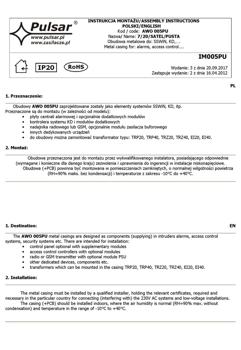
code: AWO 630
name: Enclosure DIN3/Plate/RA K 19"
metal enclosure for: SSWiN, KD,….
IM630
2nd Edition, 02 Oct 2013
Supercedes t e: 1st Edition, 02 Feb 2012
1. Intended use:
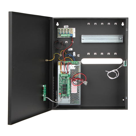
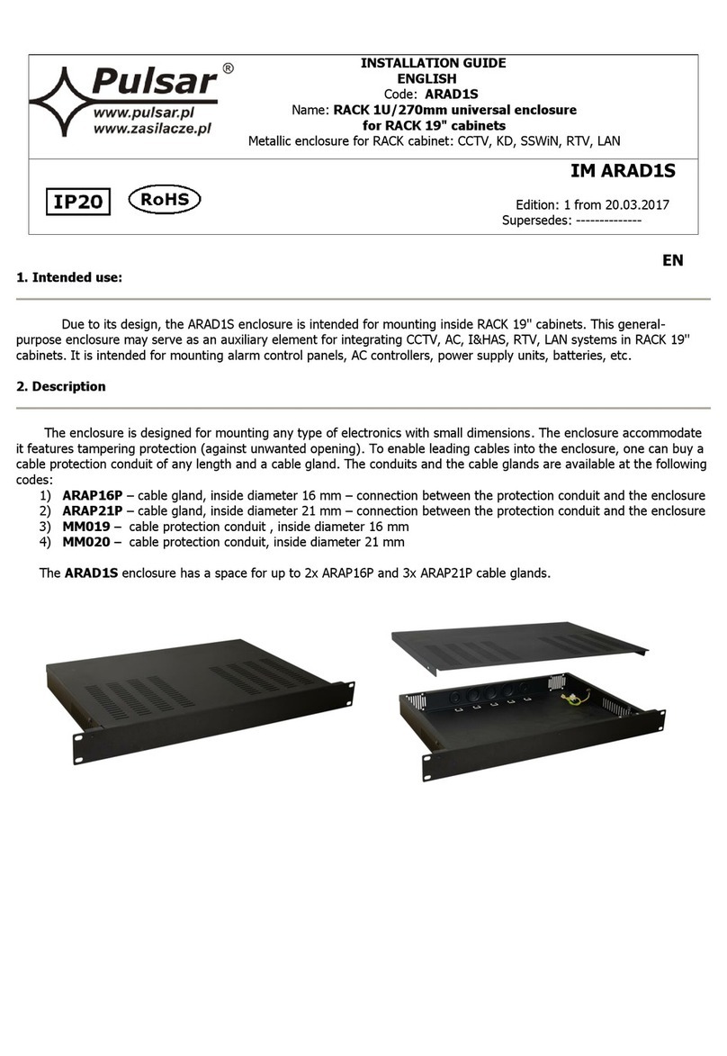
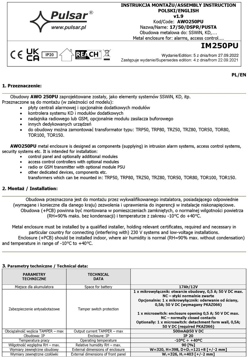
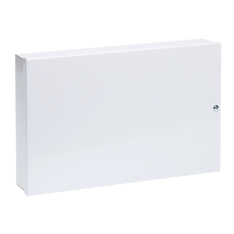
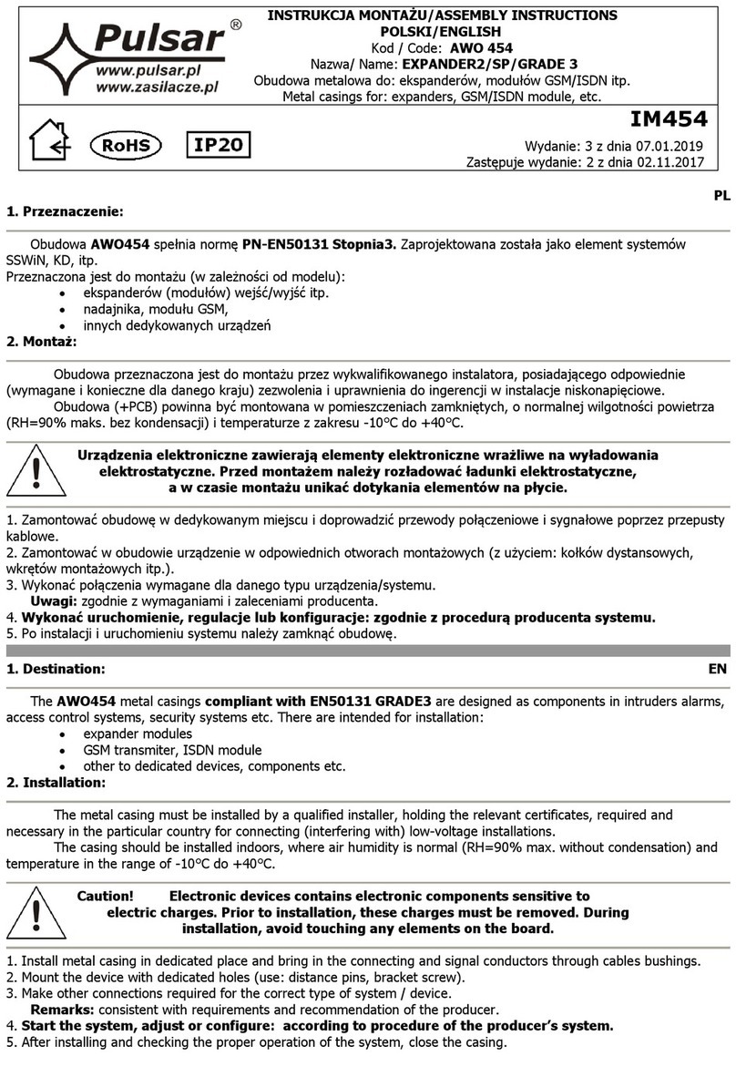
Due to its design, t e AWO630 enclosure can be used as an integrating part of installation systems, suc as: CCTV, KD,
SSWiN, LAN network, satellite TV, etc. T e enclosure is to be used for mounting (depending on configuration):
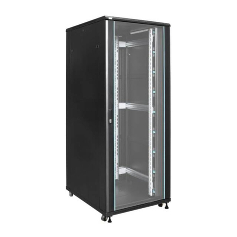
LEVEL 1: 1) rack-mount devices (RACK 19), not too deep –12U ig (wit 3 rack mounting brackets, 4U ig , w ic
can be mounted on different dept s or orizontally)
2) system KD controller and additional modules or ot er devices adjusted for mounting on a TH35 (35mm)
DIN rail
3) alarm control units and optional modules (wit additional AWO630PL mounting plate)
4) transformer, series: TRP, TRZ, TOR
5) enclosed power supply units, series: PS, PSB
LEVEL 2: 1) alarm control units and optional modules
2) ot er devices, i.e.: switc , router, etc.
2. Product description:
T e enclosure enables mounting t e devices on 2 LEVELS, at t e bottom and in t e mounting plate.
LEVEL 1:
T e enclosure, in its standard version, includes 3 DIN rails, of 480 mm, mounted to t e bottom. T ere is also an option
to add a DIN rail (AWO630DIN), max. 5 per enclosure. Instead of a DIN rail, a mounting plate (AWO630PL) of working
dimensions: 485mm x 320mm can be fitted. T e enclosure as an additional mounting plate used for installing
transformers and power supply units.
LEVEL 2:
T e enclosure is quipped wit a inged mounting plate of working dimensions: 410mm x 170mm. T at facilitates t e
access to t e devices mounted at t e bottom of t e enclosure (level1). 3 mounting plates (AWO630PLO) is a maximum
for one enclosure. T e enclosure accommodates a 65A /12V battery. Anti-tampering system indicates an unaut orized
opening of t e enclosure. T ere is also a possibility to mount an additional anti-tampering system, w ic prevents t e
PSU from being ripped off t e wall (PKAZ005). T e lock assembly as a different code (MR008). T e door, eit er rig t or
left- and, can be easily dismantled.
T e bottom part includes 2 rails t at create a 35mm space between t e enclosure and t e wall for t e cables of t e
device accommodated by t e enclosure. T is disables installing t e anti-tampering system, w ic prevents t e device
from being ripped off t e wall (PKAZ005).
3. Mounting:
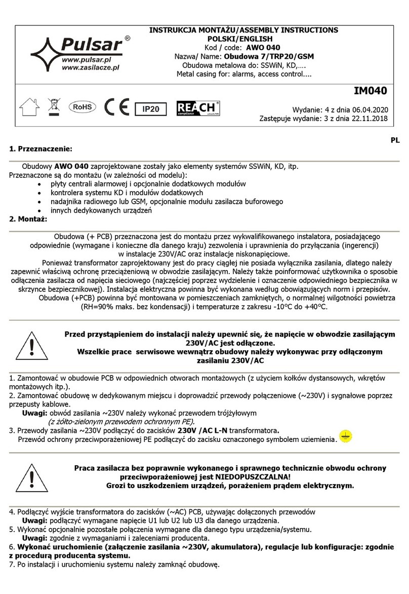
T e enclosure s all be mounted by a qualified installer wit appropriate permissions and qualifications for 230V/AC
installations and low-voltage installations (required and necessary for a given country). It s all be fitted in confined
spaces, according to t e environment class II, wit normal air umidity (RH=90% max. wit out condensation) and t e
temperature from -10°C to +40°C.

2
4. Specifications
SPECIFICATIONS
Fitting battery 65Ah/12V
Anti-tamper protection 1x – enclosure opening
TAMPER – output ampacity (max) 500mA@50Vdc
Enclosure: IP IP 20
Operating temperature -10ºC÷40ºC
Relative humidity RH – max. 90 [%]
Internal dimensions
(WxHxD) 450 x 645 x 177
[-/+2] [mm]
Additional accessories
AWO630PLO- tint metal sheet for DIN3 410mm x 170mm
(max. 3 per enclosure) - LEVEL 2
AWO 630PL- sheet metal for DIN3 485mm x 320mm – LEVEL 1
AWO630DIN- rail for DIN3 480mm - LEVEL 1 (max. 5 per enclosure)
AWO630RACK- bracket for DIN3 RACK 4U (1 set)
(max. 6 sets per enclosure)
RAS4- M6 screw set RACK 4 pcs
Lock assembly, same code MR027
Lock assembly, different code MR008
Insulating gland M20x1,5 - ML145
TAMPER, against ripping off the wall PKAZ005
Materials Sheet metal DC01, thickness: 1,0mm
Rust protection
Colour: RAL 7035 grey, texture finish
Use Inside/
Surface-mounted
Net weight ~14.65 [kg]
Gross weight ~15.00 [kg]
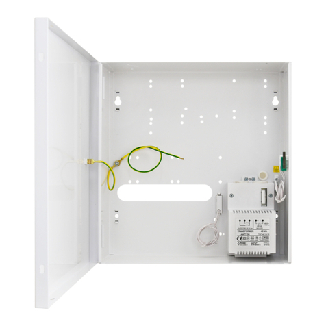
Specifications of transformers that can be mounted in the enclosure:
CODE NAME C S U I
U1 or U2 or U3
I1 or I2 or I3
F t
AWT053 TRP 20/12/14 PC/ABS
UL94 V-0
IP20 20VA 230V/AC 0,12A
12V or 14V
1,6A or 1,4A
T 200mA/250V 130
o
C
AWT050 TRP 20/16/18 PC/ABS
UL94 V-0
IP20 20VA 230V/AC 0,12A
16V or 18V
1,2A or 1,0A
T 200mA/250V 130
o
C
AWT268 TRZ 20/16/18 PC/ABS
UL94 V-0
IP43 20VA 230V/AC 0,12A
16V or 18V
1,2A or 1,0A
T 200mA/250V 130
o
C
AWT150 TRP 40/16/18 PC/ABS
UL94 V-0
IP20 40VA 230V/AC 0,20A
16V or 18V
2,2A or 2,0A
T 315mA/250V 130
o
C
AWT468 TRZ 40/16/18 PC/ABS
UL94 V-0
IP43 40VA 230V/AC 0,20A 16V or 18V
2,2A or 2,0A
T 315mA/250V 130
o
C
AWT
5161820 TRZ 50/16/18/20 PC/ABS
UL94 V-0
IP43
50VA 230V/AC 0,25A
16V or 18V or 20V
3,0A or 2,8A or 2,5A
T 500mA/250V 130
o
C
AWT
5172430 TRZ 50/17/24/30 PC/ABS
UL94 V-0
IP43 50VA 230V/AC 0,25A
17V or 24V or 30V
2,9A or 2,1A or 1,7A
T 500mA/250V 130
o
C
AWT
8161820 TRZ 80/16/18/20 PC/ABS
UL94 V-0
IP43 80VA 230V/AC 0,4A
16V or 18V or 20V
5,0A or 4,5A or 4,0A
T 630mA/250V 130
o
C
AWT
8172430 TRZ 80/17/24/30 PC/ABS
UL94 V-0
IP43 80VA 230V/AC 0,4A 17V or 24V or 30V
4,7A or 3,3A or 2,7A
T 630mA/250V 130
o
C
AWT037
TOR 50/16/18/20 - 50VA 230V/AC 0,25A 16V or 18V or 20V
3,0A or 2,8A or 2,5A
T 500mA/250V 130
O
C
AWT049
TOR 50/17/24/30 - 50VA 230V/AC 0,25A 17V or 24V or 30V
2,9A or 2,1A or 1,7A
T 500mA/250V 130
O
C
AWT039
TOR 80/16/18/20 - 80VA 230V/AC 0,4A 16V or 18V or 20V
5,0A or 4,5A or 4,0A
T 630mA/250V 130
O
C
AWT048
TOR 80/17/24/30 - 80VA 230V/AC 0,4A 17V or 24V or 30V 4,7A or 3,3A or 2,7A
T 630mA/250V 130
O
C
3
- Enclosure of a transformer
S – Supply power
U – Mains supply
I - Current consumption
at ~230V
nominal load
U1 or U2 or U3 – Secondary voltage
I1 or I2 or I3 – Nominal output current
F – F fuse in t e primary circuit of t e transformer
t - T ermal fuse 130
o
C, not resettable
Specifications of power supply units that can be mounted in the enclosure:
CODE Current Supply power Output voltage PSU type
PS251220 12V/2A 25W 12V÷15VDC Switch mode
PS401230 12V/3A 40W 12V÷15VDC Switch mode
PS601250 12V/5A 60W 12V÷15VDC Switch mode
PS1001270 12V/7A 100W 12V÷15VDC Switch mode
PS15012100 12V/10A 150W 12V÷15VDC Switch mode
PS2001214 12V/14A 200W 12V÷15VDC Switch mode
PS402418 24V/1,8A 40W 24V÷28VDC Switch mode
PS1002435 24V/3,5A 100W 24V÷28VDC Switch mode
PS2002470 24V/7A 200W 24V÷28VDC Switch mode
PS602425 24V/2,5A 60W 24V÷28VDC Switch mode
PS1502450 24V/5A 150W 24V÷28VDC Switch mode
PSB351225 13,8V/2,5A 35W 12V÷14VDC Buffer, switch mode
PSB501235 13,8V/3,5A 50W 12V÷14VDC Buffer, switch mode
PSB1001270 13,8V/7A 100W 12V÷14VDC Buffer, switch mode
PSB15512110 13,8V/11A 155W 12V÷14VDC Buffer, switch mode
PSB352413 27,6V/1,3A 35W 24V÷28VDC Buffer, switch mode
PSB502418 27,6V/1,8V 50W 24V÷28VDC Buffer, switch mode
PSB1002435 27,6V/3,5A 100W 24V÷28VDC Buffer, switch mode
PSB1552455 27,6V/5,5A 155W 24V÷28VDC Buffer, switch mode
4
Fig.1 Examples of possible configurations
PRODUCENT / PRODUCER
Pulsar K.Bogusz Sp.j.
Siedlec 150,
32-744 Łapczyca, Poland
Tel. (00 48) 14-610-19-40, Fax. (00 48) 14-610-19-50
e-mail: biuro@pulsar.pl, sales@pulsar.pl
http:// www.pulsar.pl, www.zasilacze.pl
W
ARRANTY
:
24 months from the purchase date, 36 months from the production date.
A valid proof of purchase is required.

This manual suits for next models

1

Other Pulsar Enclosure manuals

Pulsar AWO529 User manual

Pulsar

Pulsar AWO529 User manual

Pulsar AWO402 User manual

Pulsar

Pulsar AWO402 User manual

Pulsar AWO152PU User manual

Pulsar

Pulsar AWO152PU User manual

Pulsar 7/TRP20/PAR User manual

Pulsar

Pulsar 7/TRP20/PAR User manual

Pulsar 17/EIZ75/SATEL/G3 User manual

Pulsar

Pulsar 17/EIZ75/SATEL/G3 User manual

Pulsar AWO 453 User manual

Pulsar

Pulsar AWO 453 User manual

Pulsar 7/TRP20/SATEL User manual

Pulsar

Pulsar 7/TRP20/SATEL User manual

Pulsar AWO 232 User manual

Pulsar

Pulsar AWO 232 User manual

Pulsar AWO 040 User manual

Pulsar

Pulsar AWO 040 User manual

Pulsar AWO 220PU User manual

Pulsar

Pulsar AWO 220PU User manual

Pulsar AWO 224 User manual

Pulsar

Pulsar AWO 224 User manual

Pulsar AWO 360 User manual

Pulsar

Pulsar AWO 360 User manual

Pulsar AWO385 User manual

Pulsar

Pulsar AWO385 User manual

Pulsar AWO513 User manual

Pulsar

Pulsar AWO513 User manual

Pulsar LED/B SATEL User manual

Pulsar

Pulsar LED/B SATEL User manual

Pulsar AWO644 User manual

Pulsar

Pulsar AWO644 User manual

Pulsar ARAD1S User manual

Pulsar

Pulsar ARAD1S User manual

Pulsar AWO 454 User manual

Pulsar

Pulsar AWO 454 User manual

Pulsar ARAD3 User manual

Pulsar

Pulsar ARAD3 User manual

Pulsar ARAD-S4 User manual

Pulsar

Pulsar ARAD-S4 User manual

Pulsar AWO 200PU User manual

Pulsar

Pulsar AWO 200PU User manual

Pulsar AWO 500PU User manual

Pulsar

Pulsar AWO 500PU User manual

Pulsar RWA964 User manual

Pulsar

Pulsar RWA964 User manual

Pulsar AWO 515 User manual

Pulsar

Pulsar AWO 515 User manual

Popular Enclosure manuals by other brands

Icy Box IB-2811M-TB3 manual

Icy Box

Icy Box IB-2811M-TB3 manual

welland ME-700E Quick installation guide

welland

welland ME-700E Quick installation guide

Esco 90425 instruction manual

Esco

Esco 90425 instruction manual

Sharkoon S1000 manual

Sharkoon

Sharkoon S1000 manual

iStarUSA T-35HD2-SA user manual

iStarUSA

iStarUSA T-35HD2-SA user manual

Gigabyte 3D AURORA GZ-FSCA1-AN user manual

Gigabyte

Gigabyte 3D AURORA GZ-FSCA1-AN user manual

Eaton Crouse-hinds series operating instructions

Eaton

Eaton Crouse-hinds series operating instructions

HP 3PAR StoreServ 8 Series Disassembly instructions

HP

HP 3PAR StoreServ 8 Series Disassembly instructions

CARVIN TRX210N datasheet

CARVIN

CARVIN TRX210N datasheet

JL Audio Stealthbox SB-POL-GNRL/10TW3 installation guide

JL Audio

JL Audio Stealthbox SB-POL-GNRL/10TW3 installation guide

BE QUIET! PURE BASE 600 user manual

BE QUIET!

BE QUIET! PURE BASE 600 user manual

Genesis Titan 550 PLUS Quick installation guide

Genesis

Genesis Titan 550 PLUS Quick installation guide

SilverStone TS07 manual

SilverStone

SilverStone TS07 manual

APLIC 304557 user manual

APLIC

APLIC 304557 user manual

HPE Synergy 12000 Frame installation instructions

HPE

HPE Synergy 12000 Frame installation instructions

CHIEF CMA480 instructions

CHIEF

CHIEF CMA480 instructions

Icy Box IB-1814-C31 manual

Icy Box

Icy Box IB-1814-C31 manual

PCB Piezotronics IMI SENSORS 691A50/06 Installation and operating manual

PCB Piezotronics

PCB Piezotronics IMI SENSORS 691A50/06 Installation and operating manual

manuals.online logo
manuals.online logoBrands
  • About & Mission
  • Contact us
  • Privacy Policy
  • Terms and Conditions

Copyright 2025 Manuals.Online. All Rights Reserved.